Timeguard TRT049N Manual

Installation & Operating Instructions
Wiring Centre Box
Model: TRT049N

1
2
1. General Information
• These instructions should be read carefully in full before installation, and retained for
further reference and maintenance.
• Wiring diagrams are supplied for the two most popular, S-plan and Y-plan.
• This guide assumes that the installer can identify the required leads from the boiler, pump
and other controls.
• This wiring centre is suitable for all types of heating systems.
2. Safety
• Before installation or maintenance, ensure the mains supply to the wiring centre box is
switched off and the circuit supply fuses are removed or the circuit breaker turned off.
• It is recommended that a qualified electrician is consulted or used for the installation
of this wiring centre box and installed in accordance with the current IEE wiring and
Building Regulations.
• Check that the total load on the circuit including when this wiring centre box is fitted
does not exceed the rating of the circuit cable, fuse or circuit breaker.
3. Technical Specifications
• 230V AC 50 Hz
• This unit is of class II construction
• Current Rating: 10(2)A
• Installation Type: Surface mount with wall fixing kit supplied
• Operating Temperature: 0°C to 40°C
• Flame Retardant Rating: V1
• CE Compliant
• Dimensions (H x W x D): 90 x 135mm x 30mm
Cover retaining screws
Flame retardant plastic cover and case
TRT049N Front View

2
3
4 Installation
4.1 Ensure the mains supply is switched off and the circuit supply fuses are removed
or the circuit breaker turned off.
4.2 Remove the front cover from the unit, by undoing the 4 x retaining screws.
4.3 Mark the position of the mounting holes on the wall using the wall plate as a
template, and drill the holes ensuring not to infringe with any gas/water pipes or
electrical cables that may be hidden below the surface. Insert the wall plugs
into the holes.
4.4 Select a suitable cable entry point(s). Remove the required break-offs from the bottom
edge or knock-outs from the rear to accommodate the cables (a mixture of rear
and bottom entries can be used if appropriate).
4.5 Pass the 230V 50Hz mains supply and load cables thought the cable entry point(s)
and prepare for termination. Allow sufficient excess cable to wire up the unit,
but not too much to make it difficult to close the cover.
4.6 Fix the unit to the wall using the correct screws for the wall plugs installed
4.7 Terminate the cables into the terminal blocks ensuring correct polarity is observed,
and that all bare conductors are sleeved (see section xxx .Connection).
If earth continuity is required, please use the earth terminals on the right hand side.
4.8 Restore mains to the unit after checking all system wiring is complete
and replacing the front cover.
Mains
connection
points
Multiple
mounting
holes
16x wiring
terminals
Cover retainer
screw holes
4x Earth
terminals
Cable
knock outs
Cable clampsCable entry/exit
points
TRT049N Inside View
3
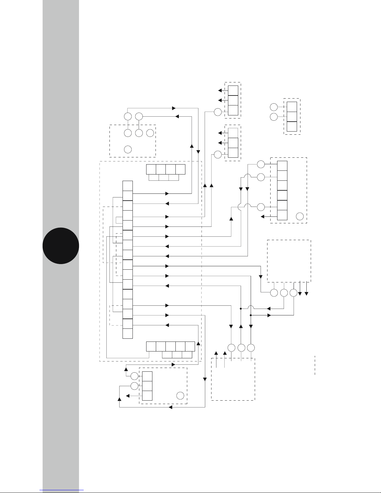
E
2
21 14
C15
12
E
N
N
LSLL
1 2 3 4 5 6 7 8 9 10 11 12 13 14 15 16
N
N
N
N
Room Thermostat Models
TRT030N
TRT031N/TRT032N
TRT033N
TRT035N
Neutral not
required on
TRT033N and
TRT035N
WIRING CENTRE TRT049N
Note: Links shown
should be made by
the installer
Cylinder Thermostat
Model TRT044
Boiler Pump
Optional Frost Stat
Model TRT031N
Programmer
Models: TRT034N
TRT036N
HW
OFF
HW
ON
CH
ON
CH
OFF
HWS
(NO)
HWC
(NC)
A/C Mains in
(5 Amp fuse)
E
E
E
E
LN
N
E
E
11
11 12
E
10 9
8
6
7
4
6
7
N
N
E
N
E13
L N
N
E
E
N L 1 2 3 4
N L SL
HW Motorised Valve
CH Motorised V
alve
Brown (L)
Brown (L)
Orange CH Call (C)
Orange CH Call (C
)
Grey HW (NO)
Gr
ey HW (NO)
Yellow/Green
Yellow/Green
Blue (N)
Blue (N)
3
5. Connection Diagrams
2 Port Motorised Valve System (S-Plan)
3
E
2
216 1 14
C15
12
E
N
N
LSLL
123456 7 8 9 10 11 12 13 14 15 16
N
N
N
N
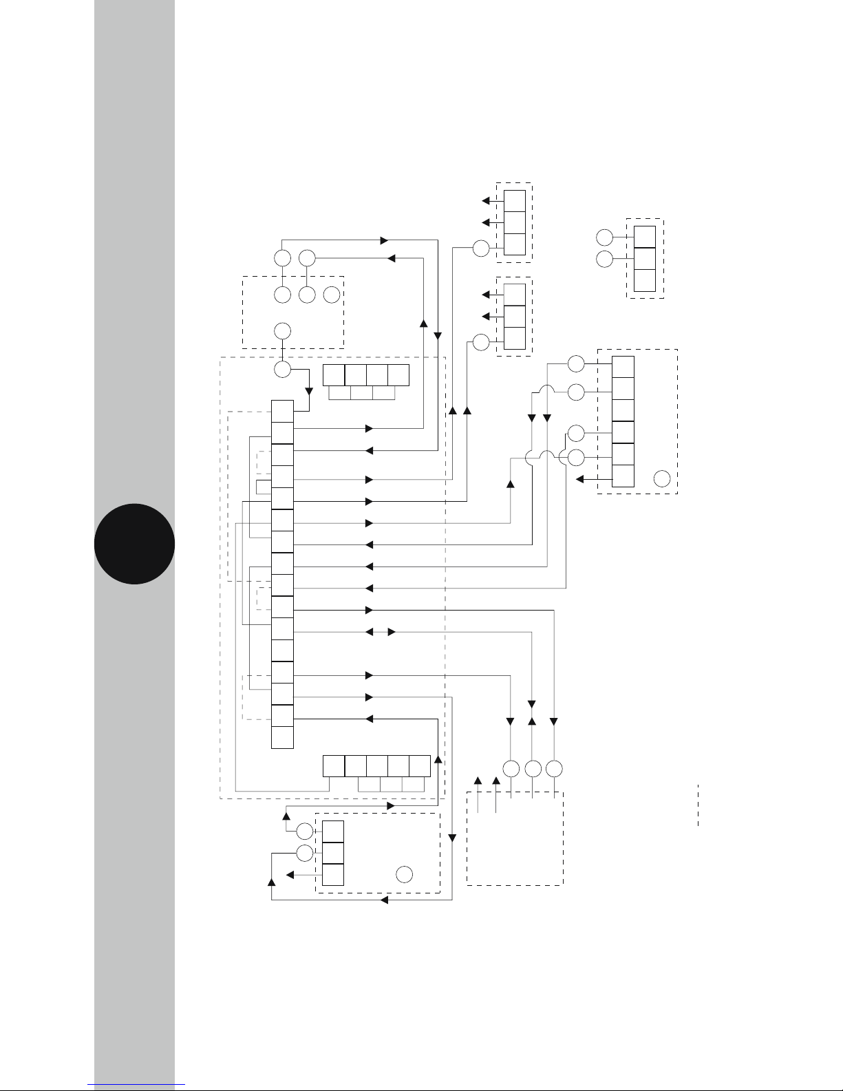
WIRING CENTRE TRT049N
Note: Links shown
should be made by
the installer
Cylinder Thermostat
Model TRT044
Boiler Pump
Optional Frost Stat
Model TRT031N
Programmer
Models: TRT034N
TRT036N
HW
OFF
HW
ON
CH
ON
CH
OFF
HWS
(NO)
HWC
(NC)
A/C Mains in
(5 Amp fuse)
E
E
E
E
L N
N
E
E
11 8
11 12
E
10 9
4
6
7
N
N
E13
L N
N
E
E
N L 1 2 3 4
N L SL
Motorised V
alve
Brown (L)
Orange CH Call (C
)
Gr
ey HW (NO)
Yellow/Green
Blue (N)
Room Thermostat Models
TRT030N
TRT031N/TRT032N
TRT033N
TRT035N
Neutral not
required on
TRT033N and
TRT035N
4
3 Port Motorised Valve System (Y-Plan)

3 Year Guarantee
In the unlikely event of this product becoming faulty due to defective material or manufacture within
3 years of the date of purchase, please return it to your supplier in the first year with proof of purchase and
it will be replaced free of charge. For the second and third years or any difficulty in the first year telephone
the helpline on 020 8450 0515.
Note: A proof of purchase is required in all cases. For all eligible replacements (where agreed by Timeguard)
the customer is responsible for all shipping/postage charges outside of the UK. All shipping costs
are to be paid in advance before a replacement is sent out.
Zerofour – February 2018
67.058.608 (Issue 1)
Timeguard Limited.
Victory Park, 400 Edgware Road,
London NW2 6ND
Sales Office: 020 8452 1112
or email csc@timeguard.com
For a product brochure please contact:
HELPLINE
020 8450 0515
or email helpline@timeguard.com
www.timeguard.com
Qualified Customer Support Co-ordinators will be on-line
to assist in resolving your query.
If you experience problems, do not immediately
return the unit to the store.
Telephone the Timeguard Customer Helpline;
Table of contents
Other Timeguard Cable Box manuals

Popular Cable Box manuals by other brands

NETGEAR
NETGEAR Cable Box user manual

Herman Miller
Herman Miller Canvas Vista Cable Management Installation and Disassembly

Channel Plus
Channel Plus DA-8200BID manual

FSR
FSR T3-IPS installation instructions

Leviton
Leviton FBBOX installation instructions

peerless-AV
peerless-AV IBA3AC Installation and assembly
