Tisira TMW228B User manual

www.tisira.com
SERVICE MANUAL
DISCLAIMER // THE INFORMATION CONTAINED IN THIS SERVICE MANUAL IS INTENDED FOR
LICENSED PERSONNEL ONLY. PLEASE CONTACT ARISIT FOR FUTHER INFORMATION.
[AUSTRALIA] 1300 762 219 [NEW ZEALAND] 09 306 1020
Version 1.3
TMW228B
28L // MICROWAVE

TMW228B
2/20
CAUTION
WARNING: Repairs must be done only by a qualied service person.
In order to prevent electric shocks:
• Before performing maintenance or repair, turn the appliance o and disconnect it from the power
supply.
• Do not touch the housing or frame of the microwave if the appliance is deemed faulty. These
components may be live.
• Ensure that the high-voltage capacitor is discharged before proceeding with any repair.
• If tests have to be performed while the appliance is live, always use a residual-current-operated circuit
breaker.
• Do not test the high-voltage circuit while the appliance is in operation. DANGER OF DEATH!
Once the repairs are completed, conduct a functional test.
PRODUCT SPECIFICATIONS
Dimensions
Voltage / Frequency
Rated Power
Microwave Power
Capacity
Turntable diametre
Net weight
W595 x D400 x H388mm
220 -240V~ / 50Hz
145W
900W
28L
Ø315mm
18.5kg

TMW228B
3/20
EXPLODED VIEW

TMW228B
4/20
EXPLODED VIEW
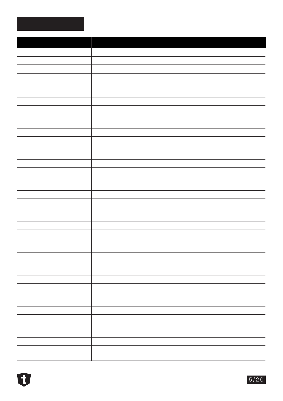
Parts List
TMW228B
5/20
ID Part Number Description
T02 2899407 TURNTABLE COUPLER
W09 2899913 LOWER COVER - WIND GUIDE
Z24 2899102 TOP COVER PANEL
C13 2899406 DOOR LEVER
C18-2 2899501 POWER BOARD
C10 & C29 2899907 DIAL KNOB
C18-1 2899502 DISPLAY BOARD
C45 2899908 DIAL SHAFT
C07 2899404 DOOR RELEASE BUTTONS
C35 2899500 BUTTONS BOARD
C01 2899405 CONTROL PANEL FRAME
C20 2899402 STOP AND START BUTTONS
C06 2899403 FUNCTION BUTTONS
T03 2899909 TURNTABLE RING ASSEMBLY
D00 2899914 WHOLE DOOR ASSEMBLY
D07 2899400 EXTERNAL DOOR PANEL
D05 2899901 DOTTED DOOR FILM
D03 2899902 SPRING FOR DOOR LATCH
D04 2899100 TOP HINGE ASSEMBLY
D02 2899903 DOOR LATCH
D08 2899401 INTERNAL DOOR PANEL
D01 2899904 DOOR FRAME ASSEMBLY
E06 2899512 CAPACITOR (high voltage)
E07 2899513 DIODE (high voltage)
B03 2899103 HINGE SUPPORT (bottom)
Z01 2899104 BRACKET FOR HIGH VOLTAGE CAPACITOR
B02 2899915 FOOT
A01 2899906 SPLASH COVER
W08 2899101 TOP COVER - WIND GUIDE
W02 2899409 FAN BLADES
W01 2899410 FAN FRAME
W03 2899505 FAN MOTOR
E01 2899510 MAGNETRON
E16 2899511 FLEXIBLE POWER CORD WITH PLUG
T01 2899503 TURNTABLE MOTOR
E05 2899509 TRANSFORMER (high voltage)
T04 2899910 TURNTABLE GLASS PLATE (315mm)
L00 2899911 INTERLOCK ASSEMBLY
L01 2899411 INTERLOCK FOR DOOR LATCH
L02 2899412 INTERLOCK LEVER

TMW228B
6/20
Parts List
ID Part Number Description
L03 2899514 MICROSWITCH (interlock)
L04 2899515 MICROSWITCH (monitor)
L05 2899516 MAIN WIRE HARNESS
C14 2899916 DISPLAY WINDOW
E10+E11 2899517 NOISE FILTER AND FUSE ASSEMBLY
E11 2899507 FUSE
E10 2899508 NOISE FILTER
W04/C43 2899408 LIGHT COVER
E13 2899504 LIGHT
F00 2801905 TRIM KIT- STAINLESS STEEL
* 2899912 ANTI-TILTING BRACKET + 3 screws
E35 2899506 THERMOSTAT 160ºC/95ºC
TMW228B
7/20
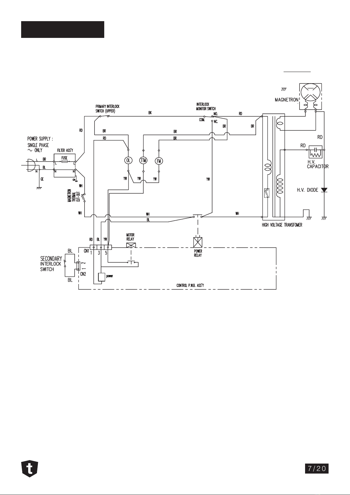
Wiring Diagram
TCO.
[ CONDITION ]
DOOR : CLOSED
COOK : OFF
NOTE :
OL : OVEN LAMP
FM : FAN MOTOR
TTM : TURN TABLE MOTOR
BK : BLACK
RD : RED
WH : WHITE
YW : YELLOW
BL : BLUE
BR : BROWN
GE : GREEN/YELLOW
TMW228B
8/20
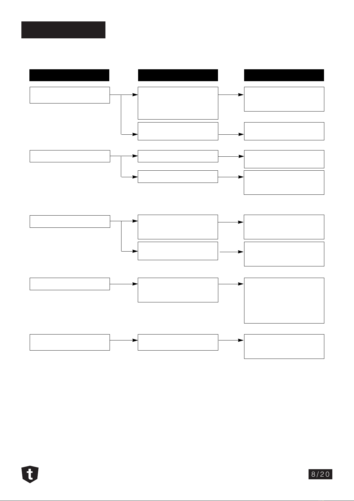
Trouble shooting
CONDITION CAUSE REMEDY
Microwave oven
does not work
Multiple devices plugged into
one power outlet and
operating at the same time
(overloading)
Avoid using other electrical
appliances when using the
microwave oven
Microwave oven plug is not
plugged in correctly
Verify if the power plug is
correctly plugged to the outlet
Output power is too low
Sparks occurring
Uneven cooking
Turntable drags and
make noises
low voltage input
Food temperature is too low
Using metallic ware and
placing them too close to the
internal walls
Use of ceramic ware trimmed
in gold or silver powder
Inconsistent intensity of
microwave by their
characteristics
The glass plate is not properly
positioned or it is overloaded
Ensure that the supplied
voltage is 220-240V
This may not be a defect.
It is possible that the food
should be cooked for longer
Do not use metallic ware for
cooking except where noted
in the cooking guide
Do not use any type of
cookware with metallic
trimming
1. Cover the thinner/smaller parts
of the food with aluminium foil
2. Use plastic wrap or lid
3. Pause the cooking process once
or twice to stir when cooking
soup, milk, etc.
Distribuite food evenly. Cook
smaller portions and/or use
lighter cookware

TMW228B
9/20
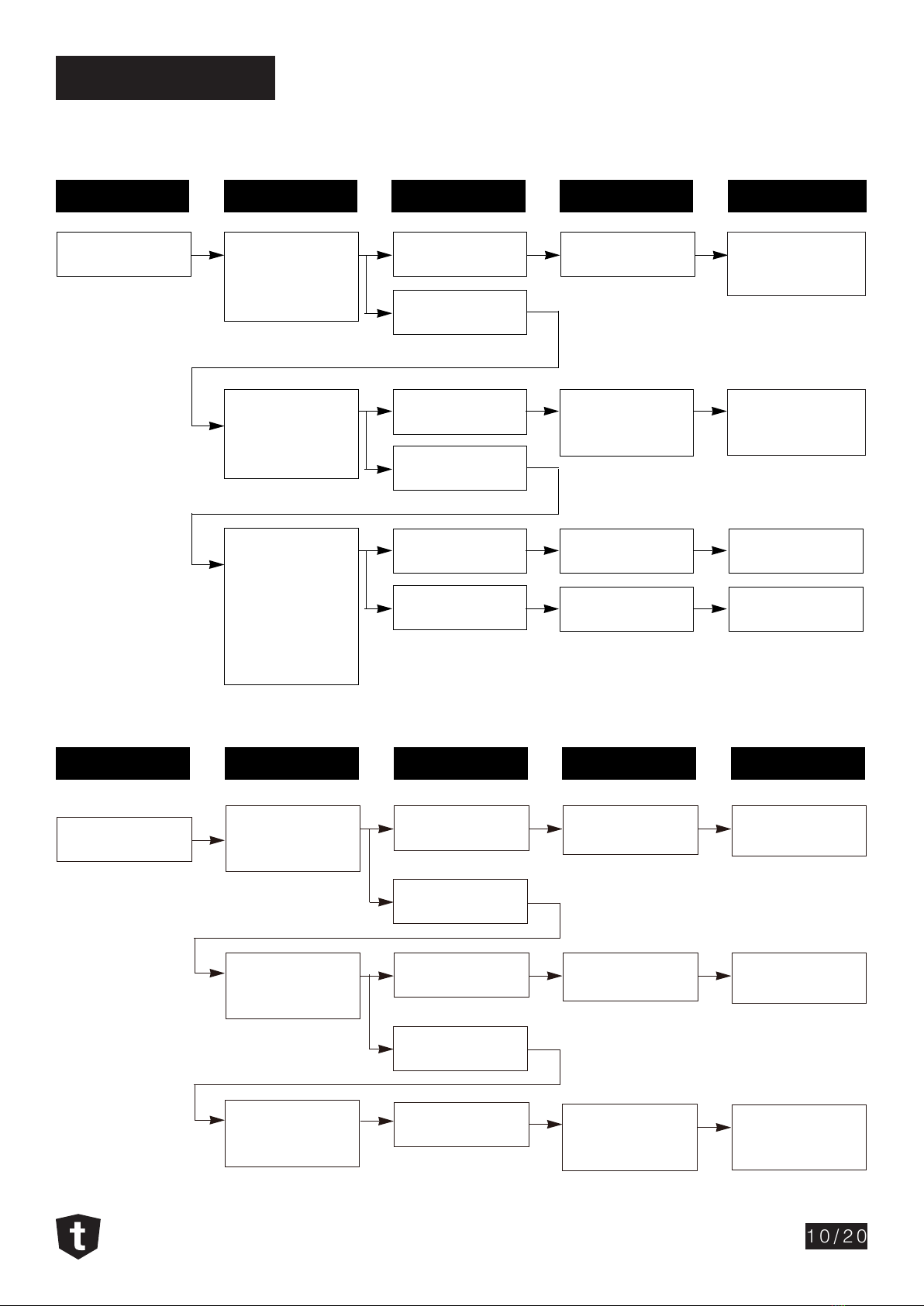
Trouble Shooting
The following display conditions indicate the possibility of a defective control circuit.
CONDITION CHECK RESULT CAUSE REMEDY
1. No input can be
programmed
check the connection
between
membrane key
assembly and PCB
assembly
Continuity
No continuity
Everything works
as specied
Still have trouble
Replace key
membrane
assembly
Defective PCB
assembly
Loose connection
Defective key
membrane
assembly
Defective PCB
assembly
Replace PCB
assembly
Check connections
Replace key
membrane
assembly
Replace PCB
assembly
2. Some inputs
can not be
programmed
3. Display shows a
number or gure
dierent to the
selection
4. Random
programming
when touching
other pads
5. Display is frozen
and can not accept
any input
TMW228B
10/20
Trouble Shooting
Microwave does not operate. Display is o and inputs cannot be entered.
CONDITION CHECK RESULT CAUSE REMEDY
1. Blown fuse Check continuity of
monitor switch (with
door closed)
Continuity Malfunction of the
monitor switch
No continuity
Replace primary
and monitor
switches
Replace fuse
Check continuity of
primary switch (with
door opened)
Continuity
No continuity
Shorted contact at
the primary switch
Replace primary
and monitor
switches
Disconnect one
side of the wire lead
connecting to the
transformer to the
high voltage
capacitor and try to
operate the unit.
Normal
Fuse blows again
Defective high
voltage capacitor
Defective high
voltage transformer
Replace high
voltage capacitor
Replace high
voltage transformer
CONDITION CHECK RESULT CAUSE REMEDY
2. Fuse is not
damaged
Check continuity of
oven thermostat
No continuity
Continuity
Defective
oven thermostat
Replace
oven thermostat
Check continuity of
magnetron
thermostat
No continuity
Continuity
Defective
magnetron
thermostat
Replace
magnetron
thermostat
Check continuity of
power supply
cord
No continuity Defective
power supply cord
Replace
power supply cord

TMW228B
11/20
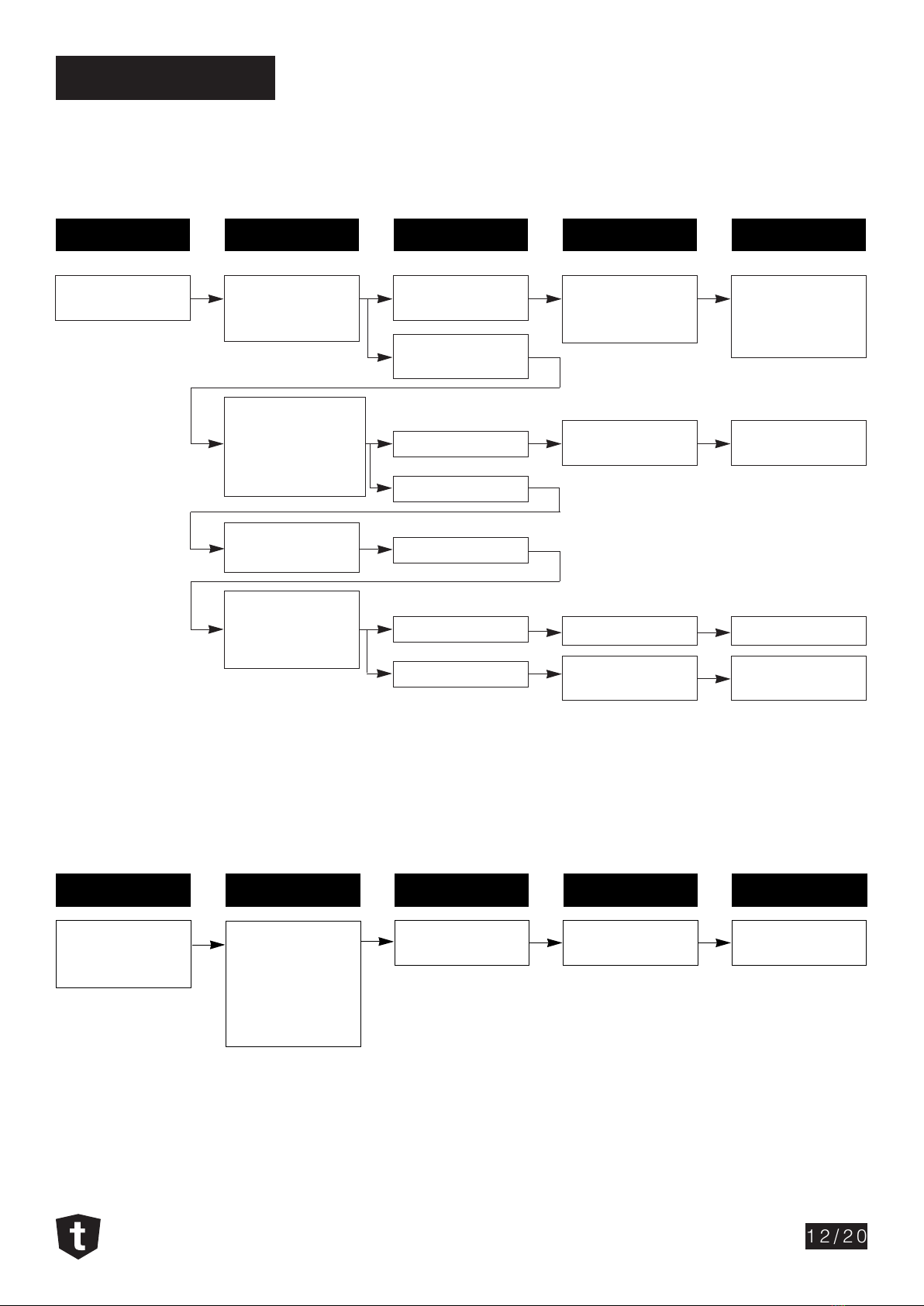
Trouble Shooting
Display is not working, but oven does not start cooking aer the desired program and time are set and
the START button is pressed.
CONDITION CHECK RESULT CAUSE REMEDY
1. Set time does not
count down when
START button is
pressed
Check continuity of
secondary switch
(with door closed)
No continuity
Continuity
Defective
secondary switch
Replace
secondary switch
Check the connection
between connector
and PCB assembly No continuity
Continuity
Loose connection
Defective
PCB assembly
Defective
fan motor
Defective
oven lamp
Check connectors
Replace PCB
assembly
Replace Fan
motor
Replace
oven lamp
Abnormal
Abnormal
Normal
Check fan motor
Check oven lamp
2. Fan motor or
oven lamp do not
turn on
TMW228B
12/20
Trouble Shooting
Microwave seems to be in operation but power output is low.
CONDITION CHECK RESULT CAUSE REMEDY
Power outlet is low Check the power
source voltage
Disconnect the wire
leads from power
relay and check on
and o time with
multitester
Measure the output
power
Check connection
between magnetron
lament terminals
and lead wires
Lower than 90% of
220-240V
Normal
Abnormal
Normal
Abnormal
Abnormal
Normal
Decrease in power
source voltage
with load
Defective PCB
assembly
Loose connection
Defective magnetron
Sugest customer to
contact local electric
power supply Co. or
qualied electrician
Replace PCB
assembly
Correct connection
Replace magnetron
Oven does not cook properly when programmed for the set power level (Operates properly at the highest
power setting)
CONDITION CHECK RESULT CAUSE REMEDY
Output is full when
you set lower power
level
Disconnect the wire
leads from power
relay and check
continuity power
relay
(Operate the unit)
Abnormal Defective PCB
assembly
Replace PCB
assembly

TMW228B
13/20
Repairing the Microwave
IMPORTANT: Ensure that the high-voltage capacitor is discharged before proceeding with any repair.
Following the steps below will provide you access to most of the components in the microwave.
1 – To remove the microwave from the cabinet cavity, remove the xing screw located underneath the
microwave door.
2 – Disconnect the power supply cord from the power outlet.
3 – Unscrew and detatch the trim kit from the microwave carcass.
4 – Remove the screws holding the bottom carcass.

TMW228B
14/20
Repairing the Microwave
5 – Remove the screws along the rear and side edges of the carcass. Slide the carcass backwards
before liing it o the unit.
Following the steps bellow will provide you access to the Turntable Motor.
1 – Remove the turntable glass plate.
2 – Carefully remove the turning sha.
3 – Lay the unit down on its back.
4 – Remove the cover of the turntable motor. Use pliers to pinch the clips that hold the cover in position.
Bottom carcass
TMW228B
15/20
Critical Components
1. High-voltage diode
The high–voltage diode can be tested the same way a standard diode is tested.
• The diode should present full continuity in conduction direction.
• The diode should present innity resistance in blocking direction.
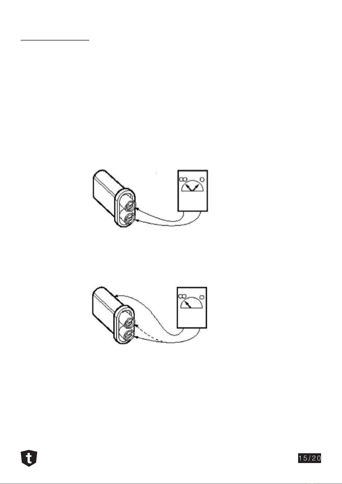
2. High-voltage capacitor
The high-voltage capacitor can be tested by resistance measurement (range 20MΩ)
The resistance between the connector of a capacitor in good working condition presents momentary
continuity followed by a resistance increase proportional to the load.
A defective capacitor presents short-circuit (continuity) permanently between its connectors.
The resistance between the connectors and the housing should be innite.
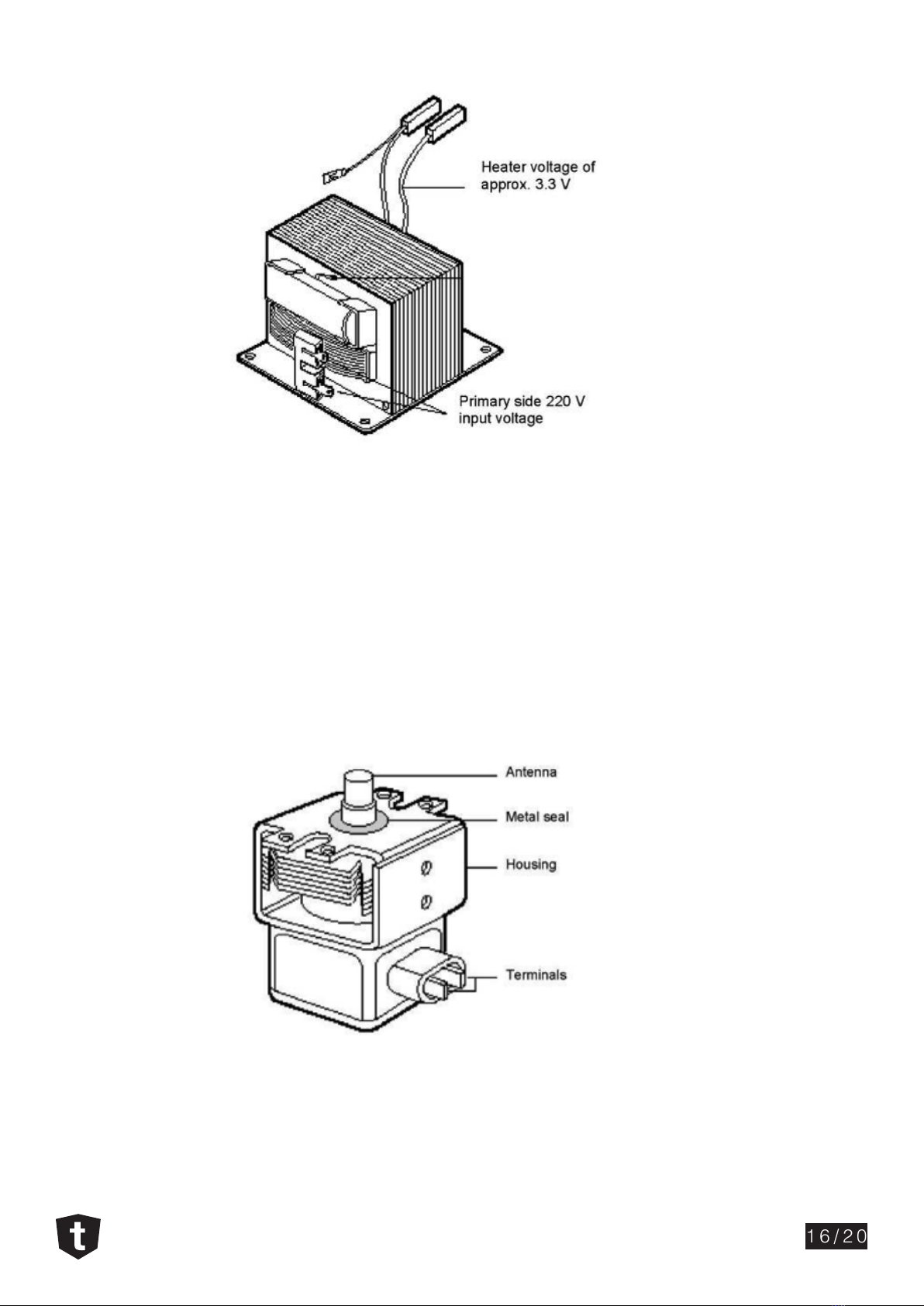
3. High-voltage transformer
This transformer supplies high voltage to the magnetron and also the operating voltage to the heater.
- Input voltage – 220-240V~
- Heater voltage – 3.3V~
- Operating voltage approx. – 2300V~
WARNING: DO NOT ATTEMPT TO MEASURE THE OPERATING VOLTAGE.
TMW228B
16/20
4. Magnetron
The magnetron can be tested by ohmic measurement only. The resistance between the terminals F and FA
should be lower than 1Ω.
The resistance between any of the terminals and the housing should be innite.
NOTE: An internal short-circuit between the cathode and anode cannot be detected by simply measuring
the terminals. This short-circuit is only detectable when the appliance is on and high voltage is being
supplied to the magnetron. Loud humming noises are also an indication of a defective magnetron.
Before installing the magnetron, ensure that the metal seal is placed correctly on top on the magnetron as
per image below.
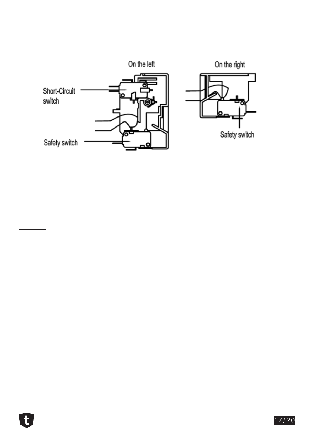
5. Safety Switches
At least 3 safety switches can be found in most microwaves models. These switches are responsible for
interrupting the generation of microwave energy as soon as the door is opened.
TMW228B
17/20
The short-circuit switch works as a safety device in case one of the safety switches doesn’t function when
required. If the short-circuit switch is activated, it will not be possible to turn the microwave on.
Safety switches operation sequence:
Open door
Safety switch on the right > Safety switch on the le > Short-circuit switch
Close door
Short-circuit switch > Safety switch on the le > Safety switch on the right

NOTES
TMW228B
18/20

NOTES
TMW228B
19/20

www.tisira.com
CONTACT DETAILS
AUSTRALIA
ARISIT PTY LIMITED
40-44 Mark Anthony Drive,
Dandenong South, VIC 3175,
Australia
P // 1300 762 219
F // 03 9768 0838
consumer.[email protected]
NEW ZEALAND
ARISIT PTY LIMITED
PO Box 68-140
Newton, Auckland 1145,
New Zealand
P // 09 306 1020
F // 09 302 0077
sales@aristonappliances.co.nz
Tisira is committed to ongoing research and
development. Every eort has been made
to ensure all information in this service
manual is correct at time of going to print.
Dimensions should be used as a reference
only and actual dimensions should be
taken from the physical product only.
Manufacturer reserves the right to change
specications without notice.
Other manuals for TMW228B
1
Table of contents
Other Tisira Microwave Oven manuals


