Tivoli Audio ADNM-DTV User manual
www.tivolilighting.com tel: 714-957-6101 fax: 714-427-3458
Copyright © 2020 Tivoli 05.20.20
ADNM-DTV Flicker-Free TV Studio Camera Installation Instructions
7170445
Page 1 of 8
Installation Instructions
Please verify the contents of the packages!
Please read instructions entirely before starting installation
Be sure power is turned off before installing or modifying the
system
Call Tivoli, LLC tech support with questions
Caution: This Power Supply is designed to work on 120-277V AC
line voltage only. Use of any other power source will cause damage,
shorten the life of the fixture and will void the warranty.
Consult any and all applicable local and national codes for
installation.
Do not conceal or extend exposed conductors through a building
wall as per local electrical code.
Warning: With any luminaire or power supply for any application,
basic safety precautions should always be followed to reduce the risk
of fire, electric shock and personal injuries. This power supply should
be installed by a certified professional.
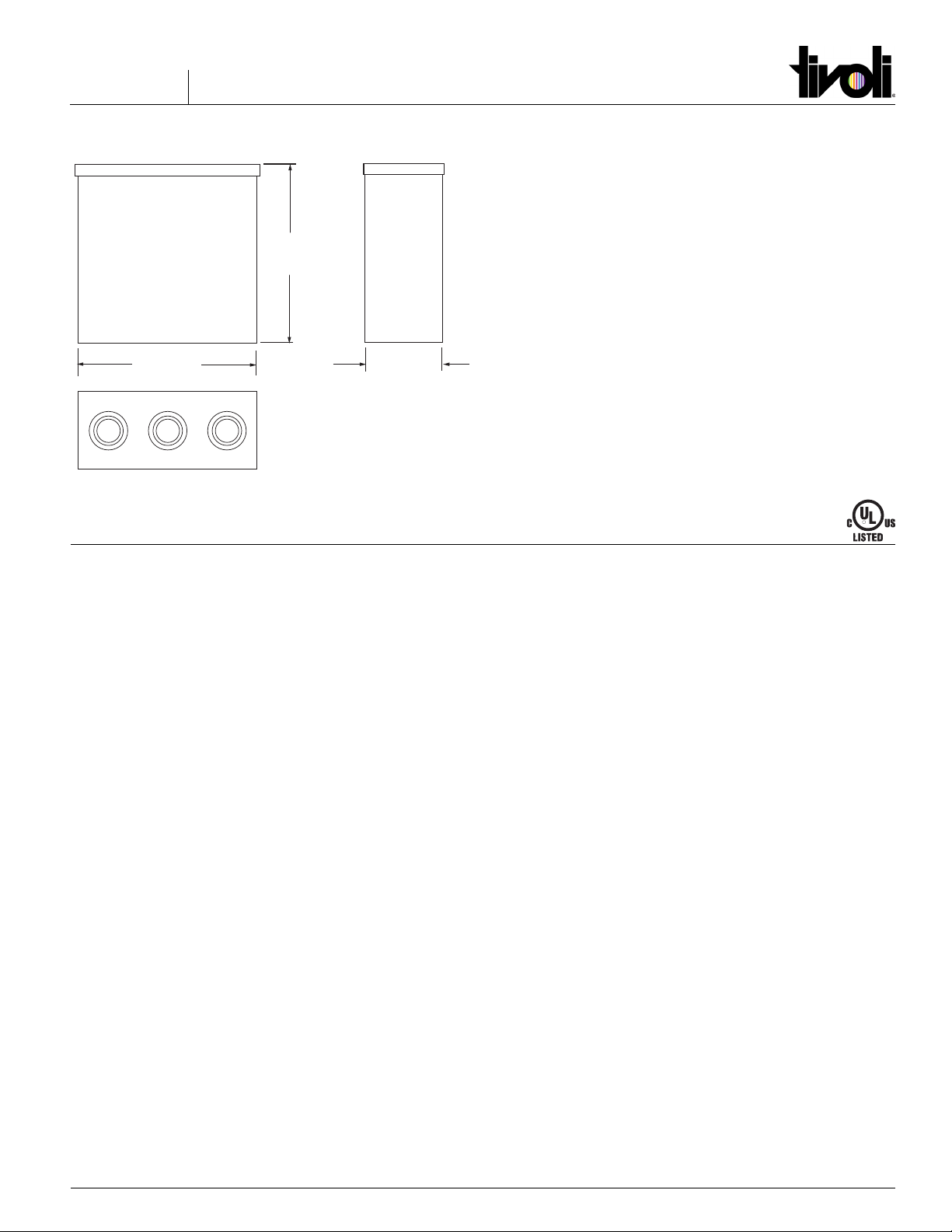
Profile Dimensions
R
10”
10” 4”
Mounting Location Requirements
It is recommended that the enclosure be mounted with at least 10”
of open space around it for proper ventilation. Do not mount next to
or above heat radiating equipment. Operating under high ambient
temperature may increase the internal temperature and will require a
de-rating in output current. This power supply will operate eciently
between -40° C to +80° C with adequate ventilation. The enclosure is
NEMA 3R rated for outdoor/wet applications.
Outdoor Installation
Step 1: Locate Power Supply enclosure (NEMA 3R rated) in a suitable
outdoor location.
Step 2: Orient the box in the proper orientation for outdoor use. The
solid cover must be positioned at the top to maintain water proof
integrity.
Step 3: Note the spacing of the mounting holes when determining
mounting location.
Step 4: Knock out access holes as needed. The 12”Box has knockouts
along the bottom of the box. The 16” does not include knockouts. Cut
out access holes where needed.
Caution! Be careful not to damage internal electrical components.
Step 5: Install strain reliefs (wire clamps) for ½”hole size. Input lead
wires are 18AWG. Output lead wires are 14AWG.
Input Connection:
Bring external Positive (Black) and Negative (White) Power Lines
through Strain Relief on the input side of the Transformer. Connect
to Black and White Transformer Leads using the correct size and UL
approved Wire Nuts.
Grounding: Connect the Green Ground Wire from inside the
enclosure and the Green Transformer wire to incoming ground wire.
Note: The 6”X 8” box has only one Ground Wire.
Warnings and Cautions
1. Risk of electrical shock and energy hazard. All failures should be
examined by a qualied technician. Do not open the case of the
power supply module.
2. Do not install LED power supplies in places with high ambient
temperature or close to a re source.

www.tivolilighting.com tel: 714-957-6101 fax: 714-427-3458Copyright © 2020 Tivoli 05.20.20
ADNM-DTV Flicker Free TV Studio Camera Installation Instructions
7170445
Page 2 of 8
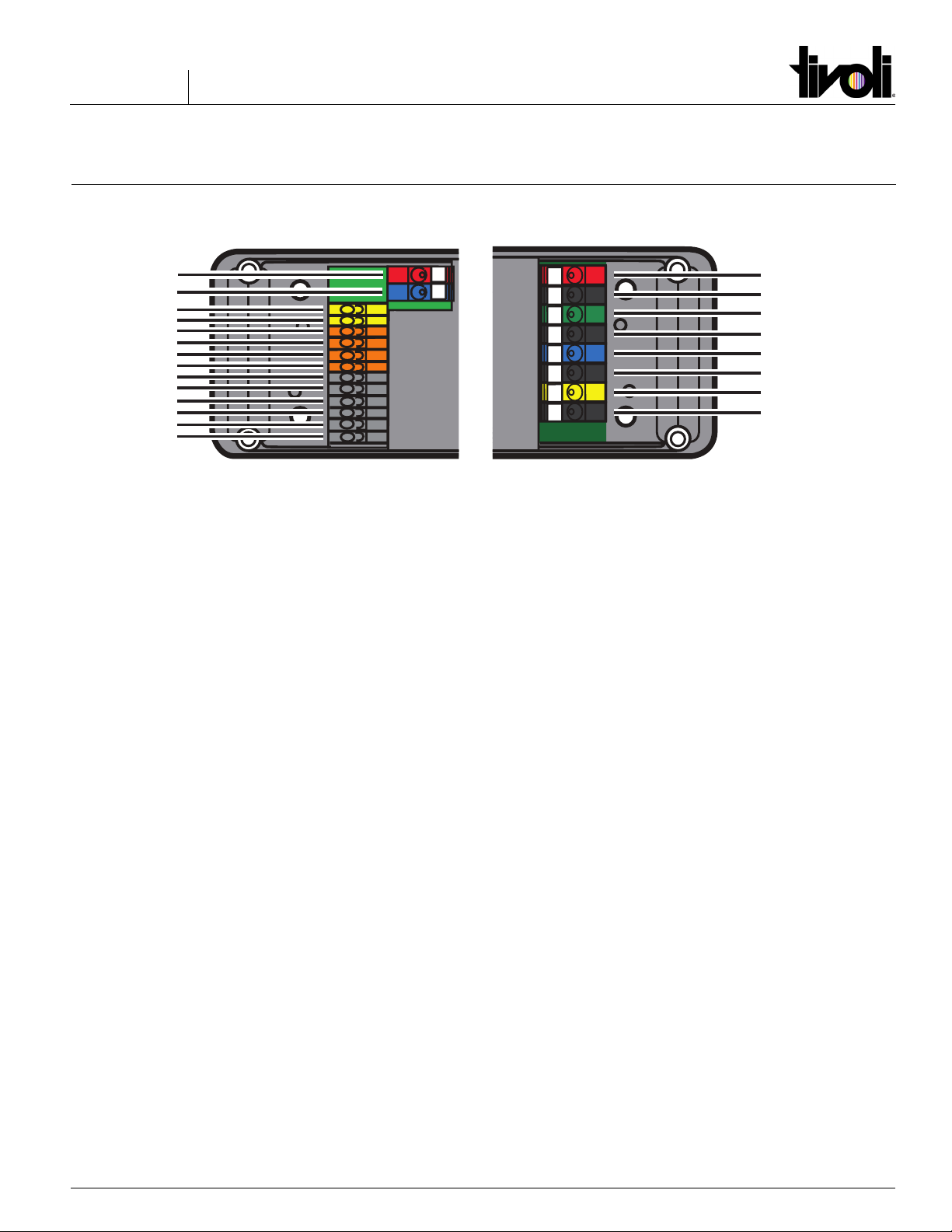
Driver Connections
Remove DTV Controller Cover: Use a small at blade screwdriver in
the open end of the cover to release it from the base.
Connect Luminaire: Connect one luminaire linear run to
eachTerminal Connector. ADNM-DTV power supplies may have from
one to four circuits, depending on model. For example, the ADNM-
320-3-4-24-DTVC can accomodate up to 3 runs of RGBW Tivotape
when each run is 17’ in length. ADNM-60-1-5-12-DVT power supply
has one circuit. Installer is responsible for selecting the right size wire
for run length and total wattage for each circuit. Do not exceed rated
watts per circuit.
Power Supply: Connect transformer input to 120-277V AC line
voltage.
Connect DMX Controller: Connect RGB controller (DMX512 signal)
to LinearDrive 720D. Connect DMX Controller to the DMX in +, DMX -
and DMX in Shield connectors.
Replace Cover: Snap the Cover back down over the base of the
controller.
M
LINEARdrive 720D
12-28V / 24W Direct voltage controlled LED driver
TC
Group 1
Group 1 GND
Group 2
Group 2 GND
Group 3
Group 3 GND
Group 4
Group 4 GND
Ext in +
Ext in -
DMX in +
DMX in -
LedSync out +
LedSync out -
LedSync shield
DA -
DA +
DA -
DA +
To Luminaire
To Power Supply
Positive (+) Wire
To Power Supply
Negative (-) Wire
To Luminaire
Positive (+) Wire
16ga
Wire
DMX In +
DMX In -
DMX In Shield
To TivoCue
www.tivolilighting.com tel: 714-957-6101 fax: 714-427-3458
Copyright © 2020 Tivoli 05.20.20
ADNM-DTV Flicker-Free TV Studio Camera Installation Instructions
7170445
Page 3 of 8
720D Driver Connections
M
LINEARdrive 720D
12-28V / 24W Direct voltage controlled LED driver
TC
Group 1
Group 1 GND
Group 2
Group 2 GND
Group 3
Group 3 GND
Group 4
Group 4 GND
Ext in +
Ext in -
DMX in +
DMX in -
LedSync out +
LedSync out -
LedSync shield
DA -
DA +
DA -
DA +
Ext in +
Ext in -
DA +
DA -
DA +
DA -
DMX in +
DMX -
DMX in shield
LedSync out +
LedSync -
LedSync shield
Channel 1, Red
Power
Channel 2, Green
Power
Channel 3, Blue
Power
Channel 4, White
Power
12V-48V DC IN
To connect the driver to a 12-48V DC power supply, connect
the power supply positive voltage supply wire to the VDC+
connector and the negative voltage supply wire to the VDC-
connector. The driver and LEDs can use the same power
supply.
EXT in
Connect an external control device to the driver’s Ext in+
and Ext in- connectors. Congure the driver for use with as
external control device over the 3-button user interface.
DA+ / DA-
Use these connectors to connect the driver to a DALI network.
Always combine a DA+ and a DA- connector for either data
input or data output.
DMX in/LEDSync out
Use these connectors when the driver is used in a DMX
network.
For DMX in, connect the network cable’s DMX+, DMX- and
DMX shielding wire (the orange/white, orange and brown wire
in a CAT5 cable) to the DMX in+, DMXin-, and DMX in shield
connector respectively.
For LEDSync out, connect the network cable’s data+, data-
and shielding wire to the LEDSync out+, LEDSync out- and
LEDSync shield connector respectively.
LED Lighting
Indicates the location of the connectors for your LED lighting.
Red represents channel 1, Green represents channel 2, Blue
represents channel 3 and White represents channel 4. The
default group color allocation can be changed over the 3
button user interface.

www.tivolilighting.com tel: 714-957-6101 fax: 714-427-3458Copyright © 2020 Tivoli 05.20.20
ADNM-DTV Flicker Free TV Studio Camera Installation Instructions
7170445
Page 4 of 8
Why choosing the right cable is important
External disturbances
DMX is a balanced three wire system. Two wires carry the data signals and one wire acts as common reference. The advantage of a balanced syste
m
is that external disturbance signals (EMI or electromagnetic interference) can easily be reduced. Both signal lines in a balanced system carry the sa
me
signals with opposite polarity which are subtracted from each other at the driver.
DMX cables should have twisted pair conductors. This means that each pair of wires in the cable are twisted together. This ensu
res that any external
disturbance signal will occur equally on both signal wires (DMX in + and DMX in -). Since the driver subtracts signals on both wires, the equal
disturbance signals will also be subtracted from each other and are cancelled out.
The use of a shielded cable can further reduce EMI eects. The shield prevents external disturbances from reaching the signal wires. If a shielded
cable is used, do not connect the DMX shield to the mains ground.
Reections
DMX works with high frequency signals. In an unterminated cable, thise signals will be reected when they reach the end of the cable. These
reections can cause eratic behavior lake random ashing lights, wrong brightness levels, etc.
To get the most reliable operation with minimal or no reections. DMX cables should have an impedence of 120Ω as described in the DMX 512
standard. Cable designed specically for DMX (or RS-485) applications is readily available and also contains a shield wire; for instance, Belden 9841
cable. In some installations Cat5 or Cat6 UTP cable can also be used. At the last driver, the cable must be terminated with a 120Ω resistor to prevent
reections. Signal loss between the controller and the last driver must be less than 328 yards.
There is also signal loss because of the loading of the connected drivers. The DMX512 standard states that a maximum of 32 unit loads can be
connected to one DMX cable. One driver is one unit load. If the total unit load exceeds 32, a splitter, repeater or booster can
be used. Note, however,
that repeaters, boosters and splitters may also add to the total unit load.
EMI reduced with balanced system
DMX
Signal
Split in
DMX + and DMX-
External disturbance on
DMX+ and DMX- wires
Subtract DMX+ and DMX-
to get the original signal
Subtract
Ideal Signal Signal With Reections
DMX Controller
DMX Driver 1 DMX Driver 32
DMX
Repeater/
Booster/
Splitter DMX Driver
DMX Cable
Termination
Resistor
Termination
Resistor
More than 32 unit loads
RGB LED RGB LED RGB LED
Why Choosing The Right Cable Is Important
www.tivolilighting.com tel: 714-957-6101 fax: 714-427-3458
Copyright © 2020 Tivoli 05.20.20
ADNM-DTV Flicker-Free TV Studio Camera Installation Instructions
7170445
Page 5 of 8
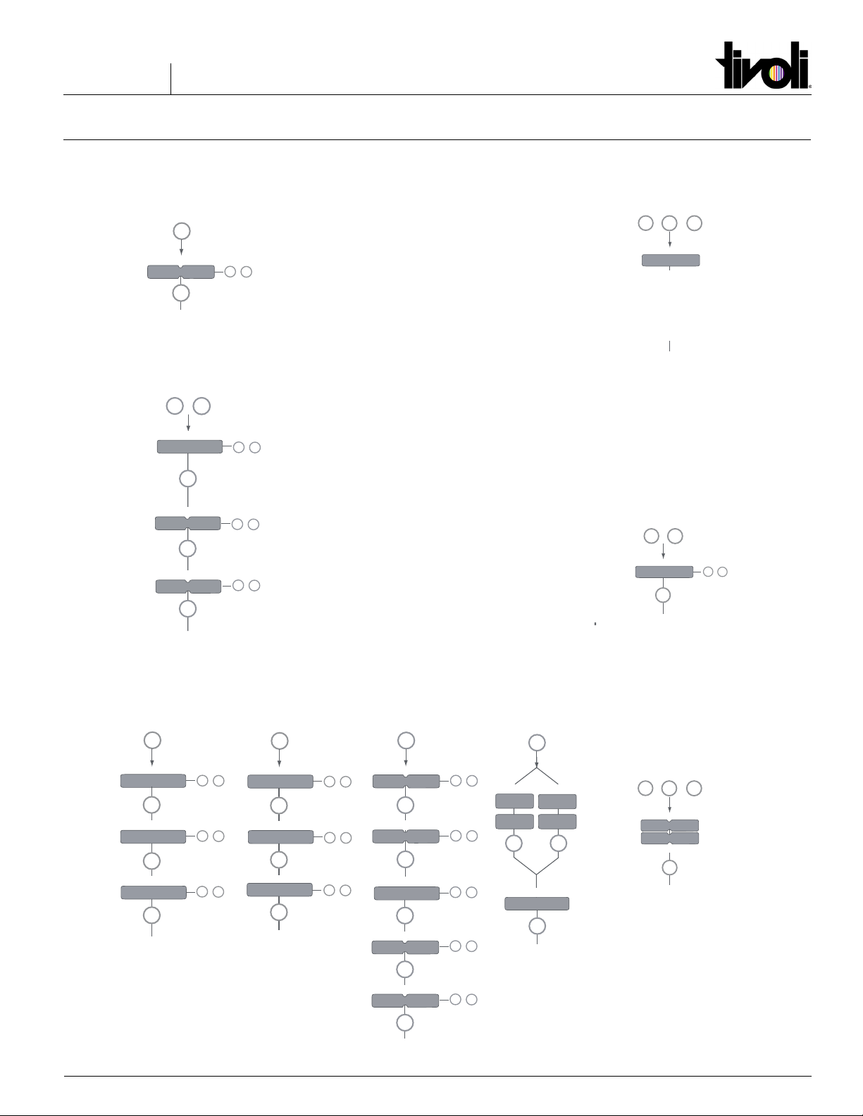
Quick Start Guide
Manual configuration
1. Select mode of operation
2. Set LED groups
3. Standalone Standalone Networked
operation or operation or operation
- Colour*- - Show - - DMX or DALI -
* The colour menu depends on the LED
group settings you have selected in step 2.
M
display off
SHOW
COLR
DMX
DALI
(5 sec)
M
+-
/
Set mode
MODE
SET
RGB
RGBW
RGBA
RRGB
RGGB
CCWW
CWWW
1-1L
2-2L
3-3L
4-4L
2-4L
1-4L
M
M
+
+-
/
LED groups
LED
+
OFF
POTM
10V
SWIT
display off
M
+-
/
External input
EXT INP
+-
/
LOG
LIN
Dimming curve
M
DIM CURV
+-
/
OFF
VID
COLR
WHIT
GLOW
M
M
M
M
+-
/
+-
/
1...512
Network resolution
DMX address
8 BT
16 BT
ADDR
DMX
RES
NETW
Interpolation
+-
/
AUTO
MANU
display off
M
NETW
Network setup
SET
+-
/
YES
NO
DMX termination
TERM
M
INTERPOL
00...20
M
display off
SHOW
M
M
M
-99...99
0...255
+-
/
+-
/
+-
/
Intensity
Speed
Show
SPD
INT
M
HUE
M
HUE
White
WHIT
M
M
+-
/
Intensity
0...255
INT
display off
+-
/
0...1535
+-
/
0...255
M
ADDR
NO
SETADDR
MM
display off
Nr. of ballasts
No address Address set
X BAL
M
Other features
Visual test run
Locking the configuration
Reset to factory defaults
M
display off
TEST
-
+
Test
+ +
R 1 sec
G 1 sec
B 1 sec
W 1 sec
RGBW 1 sec
R 1 sec
G 1 sec
B 1 sec
W 1 sec
RGBW 1 sec
+-
/
display off
M
LOCK
M
+
Lock driver
+(5 sec)
NO
SOFT
HARD
M
display off
RE - SET
-
+
Reset
+ +
M
(5 sec)
Press menu
PRES MENU

www.tivolilighting.com tel: 714-957-6101 fax: 714-427-3458Copyright © 2020 Tivoli 05.20.20
ADNM-DTV Flicker Free TV Studio Camera Installation Instructions
7170445
Page 6 of 8
Conguration Options
eldoLED B.V. Science Park Eindhoven 5125 5692 ED Son The Netherlands T +31 40 782 0400 [email protected]
Connecting an RGB LED strip
Maximum current per output: 6A
Connecting an RGB strip and a white LED strip
Maximum current per output: 6A
Connecting warm white and cool white LED strips
Maximum current per output: 6A
Connecting four white or self-colored LED strips
Maximum current per output: 6A
White LED strip
TC
Group 1
Group 1 GND
Group 2
Group 2 GND
Group 3
Group 3 GND
Group 4
Group 4 GND
32A
PSU
6A 6A 6A 6A
+
-
+
-
White LED strip
+
-
White LED strip
+
-
White LED strip
+
-
6A 6A 6A 6A
6A
6A
6A
6A
24A 24A
Warm White LED strip
TC
Group 1
Group 1 GND
Group 2
Group 2 GND
Group 3
Group 3 GND
Group 4
Group 4 GND
32A
PSU
6A 6A 6A 6A
+
-
+
-
Cool White LED strip
+
-
Warm White LED strip
+
-
Cool White LED strip
+
-
6A 6A 6A 6A
6A
6A
6A
6A
24A 24A
TC
Group 1
Group 1 GND
Group 2
Group 2 GND
Group 3
Group 3 GND
Group 4
Group 4 GND
RGB LED strip
+
R
G
B
32A
PSU
6A 6A 6A 6A 6A
6A
6A
6A
+
-
+
-
White LED strip
6A
24A 24A
18A
TC
Group 1
Group 1 GND
Group 2
Group 2 GND
Group 3
Group 3 GND
Group 4
Group 4 GND
RGB LED strip
+
R
G
B
32A
PSU
6A 6A 6A
+
-
6A
6A
6A
18A
18A
Use a star connection for the ground wires and keep the
length of the wires that deal with high amperages
under10 - 15cm / 3.9 - 5.9 inch.
Conguration of the LED groups:
Press M and + simultaneously, in the LED menu
choose RGB and save this setting by pressing M.
Use a star connection for the ground wires and keep the
length of the wires that deal with high amperages
under10 - 15cm / 3.9 - 5.9 inch.
Conguration of the LED groups:
Press M and + simultaneously, in the LED menu
choose RGBW and save this setting by pressing M.
Use a star connection for the ground wires and keep the
length of the wires that deal with high amperages
under10 - 15cm / 3.9 - 5.9 inch.
Conguration of the LED groups:
Press M and + simultaneously, in the LED menu
choose 4-4L and save this setting by pressing M.
Use a star connection for the ground wires and keep the
length of the wires that deal with high amperages
under10 - 15cm / 3.9 - 5.9 inch.
Conguration of the LED groups:
Press M and + simultaneously, in the LED menu
choose 1-4L and save this setting by pressing M.
www.tivolilighting.com tel: 714-957-6101 fax: 714-427-3458
Copyright © 2020 Tivoli 05.20.20
ADNM-DTV Flicker-Free TV Studio Camera Installation Instructions
7170445
Page 7 of 8
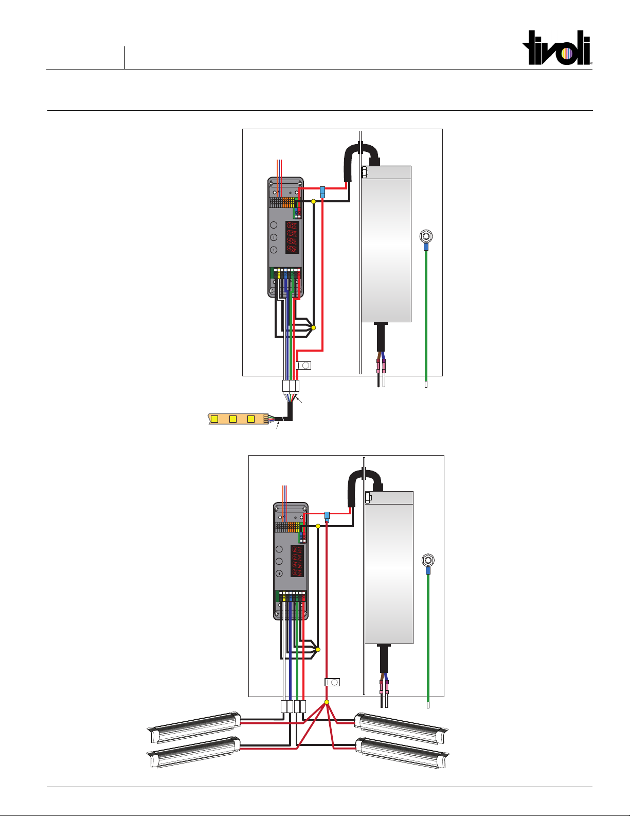
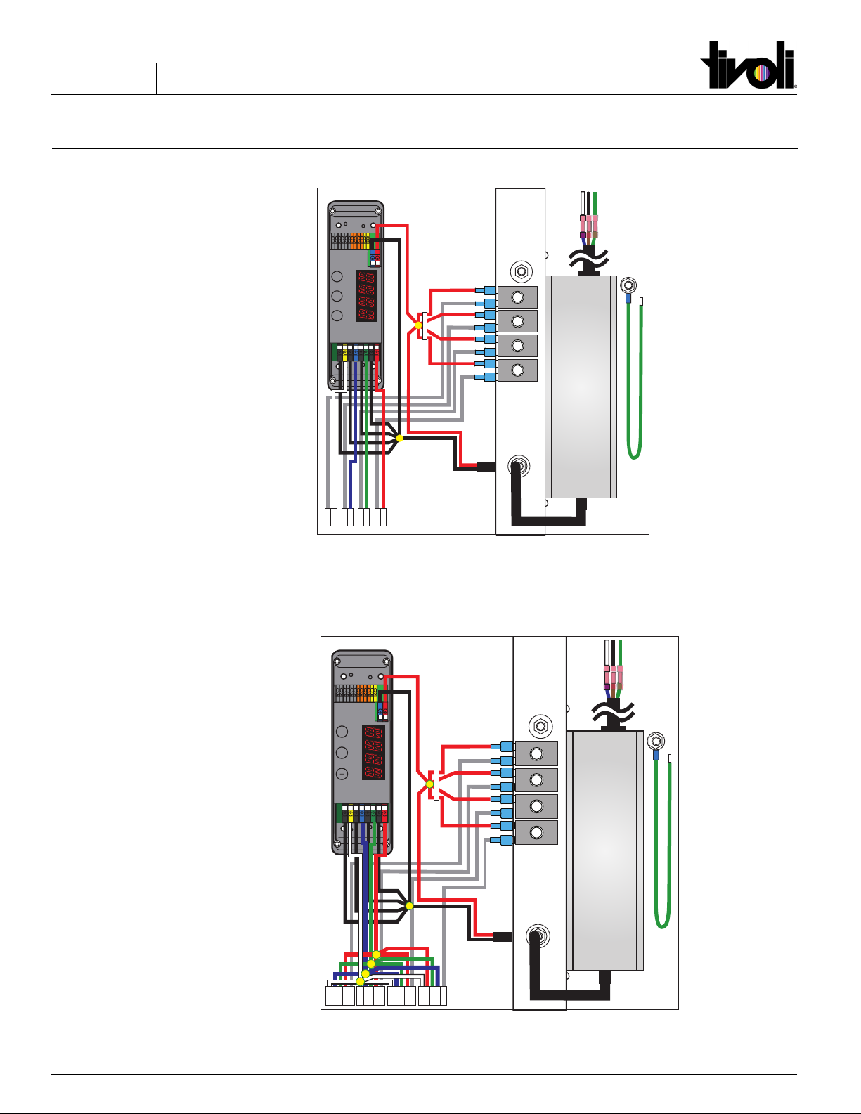
DTV Basic Wiring Diagrams
POWER
SUPPLY
Incoming
Power
GND
M
LINEARdrive 720D
12-28V / 24W Direct voltage controlled LED driver
TC
Group 1
Group 1 GND
Group 2
Group 2 GND
Group 3
Group 3 GND
Group 4
Ext in +
Ext in -
DMX in +
DMX in -
LedSync out +
LedSync out -
LedSync shield
DA -
DA +
DA -
DA +
To Power Supply
Positive (+) Wire
To Power Supply
Negative (-) Wire
To Luminaire
Positive (+) Wire
16ga
Wire
DMX In +
DMX In -
DMX In Shield
To TivoCue
+
22ga Wire
+
G
R
B
W
Lead Wire
WB G R
12V DC RGB Luminaire
ADNM-60-1-5-12-DTV
Outdoor (Nema 3 Rated)
60W / 1 Circuit X 5A / 1 EldoLED Control
Box Size: 10”W X 10” L X 4”D
POWER
SUPPLY
Incoming
Power
GND
M
LINEARdrive 720D
12-28V / 24W Direct voltage controlled LED driver
TC
Group 1
Group 1 GND
Group 2
Group 2 GND
Group 3
Group 3 GND
Group 4
Ext in +
Ext in -
DMX in +
DMX in -
LedSync out +
LedSync out -
LedSync shield
DA -
DA +
DA -
DA +
To Power Supply
Positive (+) Wire
To Power Supply
Negative (-) Wire
To Luminaire
Positive (+) Wire
16ga
Wire
DMX In +
DMX In -
DMX In Shield
To TivoCue
WB G R
+
12V DC Static Tape Light
www.tivolilighting.com tel: 714-957-6101 fax: 714-427-3458Copyright © 2020 Tivoli 05.20.20
ADNM-DTV Flicker Free TV Studio Camera Installation Instructions
7170445
Page 8 of 8
M
LINEARdrive 720D
12-28V / 24W Direct voltage controlled LED driver
TC
Group 1
Group 1 GND
Group 2
Group 2 GND
Group 3
Group 3 GND
Group 4
Group 4 GND
Ext in +
Ext in -
DMX in +
DMX in -
DMX in shield
LedSync out +
LedSync out -
LedSync shield
DA -
DA +
DA -
DA +
POWER
SUPPLY
Input
Output
16ga
Wire
+ - + - + - + -
+
-
Incoming Power
To Luminaire
(4 Circuits)
M
LINEARdrive 720D
12-28V / 24W Direct voltage controlled LED driver
TC
Group 1
Group 1 GND
Group 2
Group 2 GND
Group 3
Group 3 GND
Group 4
Group 4 GND
Ext in +
Ext in -
DMX in +
DMX in -
DMX in shield
LedSync out +
LedSync out -
LedSync shield
DA -
DA +
DA -
DA +
POWER
SUPPLY
Input
Output
16ga
Wire
+
-
Incoming Power
To Luminaire
(4 Circuits)
DTV Basic Wiring Diagrams
ADNM-240-4-5-12-DTV
Outdoor (Nema 3 Rated)
240W / 4 Circuit X 5A / 1 EldoLED Controls
all circuits
Box Size: 16”W X 16”W X 4D”
ADNM-320-3-4-24-DTVC
Outdoor (Nema 3 Rated)
240W / 3 Circuit X 5A / 1 EldoLED Controls
all circuits for RGB/RGBW
Box Size: 16”W X 16”W X 4D”
Table of contents
Other Tivoli Audio Transformer manuals


 Installation and commissioning guide")
