Safety First!
Before connecting and using the
equipment, please read thisQuick-Start
Guide carefully and keep it for future
reference.
WARNING!This equipment has been designed
to be installed byqualified professionals
only! There are many factors to be considered
when installing professional sound
reinforcementsystems,including mechanical
and electricalconsiderations, as well as
acoustic coverage and performance. Mackie
Industrial strongly recommends that this
equipment be installed only by a professional
sound installer or contractor.
1. Read Instructions—Allthe safetyand
operation instructionsshould be read
before this Mackie Industrialproduct is
operated.
2. Water and Moisture—This Mackie Industrial
product should not be used near water –
for example, near a bathtub, washbowl,
sink, in a damp cellar, near a swimming
pool, etc.
3. Foreign bodiesand liquids—Be careful not
to allow any foreign bodiesor liquids to get
into this Mackie Industrial product.
4. Technicalservice—The user should never
attempt to make anyrepairson this Mackie
Industrial product unless otherwise
indicated in the instruction manual. All
repairs should be made bya qualified
servicetechnician.
5. Installation—Do not install this Mackie
Industrialproductin any way that isnot
indicated in the instruction manual.
6. Respectthe safety standards—The entire
sound system must be created in
compliance with the current standards and
laws regarding electrical systems.
Part No. 910-003-20 Rev. C 05/01
© 2001 Mackie Industrial. All Rights Reserved. Printed in Italy.
www.mackieindustrial.com
16220 Wood-Red Road NEWoodinville, WA 98072
PATX60
70V/100VTransformerPanel
Quick-Start Guide
The PATX60 is a 70V/100V transformer panel that
replaces the connector panel on the Vision Series
PACX81, PA261, and PA281. It has a 60 watt, 70 Volt
transformer with a terminal strip for external
connections to a 70V or 100V constant-voltage
amplifier.
SERIAL NUMBER MANUFACTURING DATE
CAUTION:
SUSPENDING THIS SYSTEM SHOULD BE DONE BY QUALIFIED
TECHNICIANS FOLLOWING APPROPRIATE SAFETY STANDARDS
CONCEIVED, DESIGNED, AND MANUFACTURED BY MACKIE
INDUSTRIAL • MADE IN ITALY • COPYRIGHT ©2000 • THE FOLLOWING
ARE TRADEMARKS/REGISTERED TRADEMARKS OF MACK IE DESIGN INC :
"MACKIE", "MACKIE INDUSTRIAL", & THE "RUNNING MAN" FIGURE
70V
COM
NC
60W
30W
COM
60W
30W
15W
100V
70V
100V
PATX 60
VISION
SERIES
SERIAL NUMBER MANUFACTURING DATE
CAUTION:
SUSPENDING THIS SYSTEM SHOULD BE DONE BY QUALIFIED
TECHNICIANS FOLLOWING APPROPRIATE SAFETY STANDARDS
CONCEIVED, DESIGNED, AND MANUFACTURED BY MACKIE
INDUSTRIAL • MADE IN ITALY • COPYRIGHT ©2000 • THE FOLLOWING
ARE TRADEMARKS/REGISTERED TRADEMARKS OF MACKIE DESIGN INC :
"MACKIE", "MACKIE INDUSTRIAL", & THE "RUNNING MAN" FIGURE
70V
COM
NC60W
30W
COM
60W
30W
15W
100V
70V
100V
PATX 60
VISION
SERIES
70V CONSTANT-VOLTAGE DISTRIBUTION SYSTEM
+
–
70V CONSTANT-VOLTAGE
POWER AMPLIFIER
SERIAL NUMBER MANUFACTURING DATE
CAUTION:
SUSPENDING THIS SYSTEM SHOULD BE DONE BY QUALIFIED
TECHNICIANS FOLLOWING APPROPRIATE SAFETY STANDARDS
CONCEIVED, DESIGNED, AND MANUFACTURED BY MACKIE
INDUSTRIAL • MADE IN ITALY • COPYRIGHT ©2000 • THE FOLLOWING
ARE TRADEMARKS/REGISTERED TRADEMARKS OF MACKIE DESIGN INC :
"MACKIE", "MACKIE INDUSTRIAL", & THE "RUNNING MAN" FIGURE
70V
COM
NC60W
30W
COM
60W
30W
15W
100V
70V
100V
PATX 60
VISION
SERIES
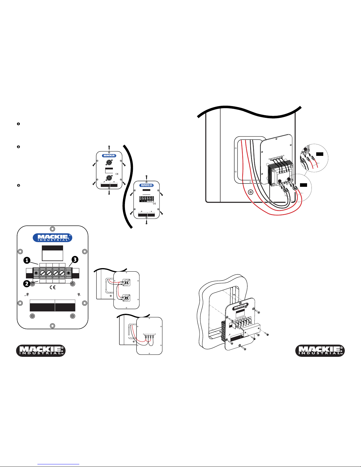
70V LINE
Strip the speaker wiring back about 1/2", loosen the
screw enough to loop the wire around the shaft of the
screw (clockwise), and tighten down the screw with a
slot-head screwdriver.
Note: Make sure the taps on the speakers add up to
no more than the rated power for the amplifier being
used.
Connecting the PATX60
to a Constant-Voltage
Distribution System
In a constant-voltage distribution system, all the
speakers are connected in parallel. This makes it
easy to add or remove speakers from the system
without having to recalculate the impedance of the
load on the amplifier.
Simply add the taps on the speakers connected to
the system and make sure the total power indicated
by the taps does not exceed the rated power of the
amplifier.