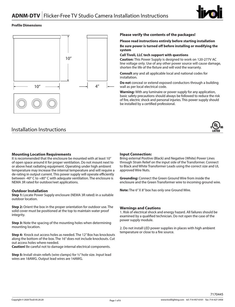
Tivoli Audio ADNM Series User manual

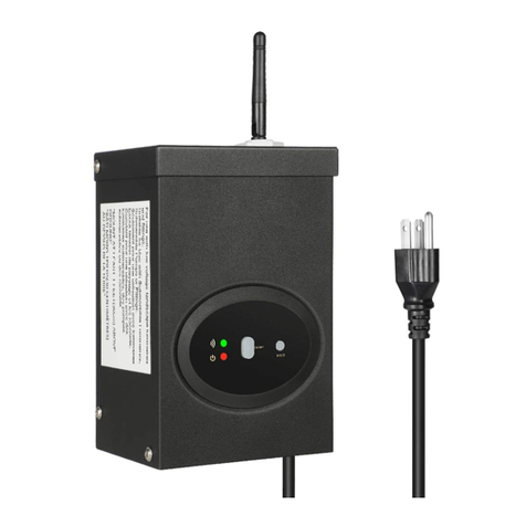
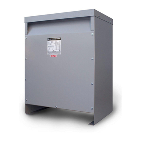
ADNM DTV NEMA 3 (TV Studio Camera Flicker Free)
www.tivolilighting.com tel: 714-957-6101 fax: 714-427-3458
Page 1 of 6
Copyright © Tivoli 07/08/20
Tivoli, LLC. reserves the right to modify this specication without prior notice.
R
DESCRIPTION CAT N O APPLICATION PRIMARY
VOLTAGE
SECONDARY
VOLTAGE
CIRCUIT
BREAKERS MAX LOAD CIRCUIT
CAPACITY DIMENSION
ADNM Series
Class 2
ADNM601512DTV
INDOOR /
OUTDOOR
100277V AC
⁄ Hz
12V DC
1 60W
5A
10”W X 10” L X 4” D
ADNM1502512DTV 2 2x60W 12”W X 12” L X 4” D
ADNM2404512DTV 4 4x60W 16”W X 16” L X 4” D
ADNM601512DTVC 1 60W 10”W X 10” L X 4” D
ADNM1502512DTVC 2 2x60W 12” W X 12” L X 4” D
ADNM2404512DTVC 4 4x60W 16” W X 16” L X 4” D
ADNM1201424DTV
24V DC
1 96W
4A
12”W X 12” L X 4” D
ADNM2402424DTV 2 2x96W 12”W X 12” L X 4” D
ADNM3203424DTV 3 3x96W 16”W X 16” L X 4” D
ADNM1201424DTVC 1 96W 12” W X 12” L X 4” D
ADNM2402424DTVC 2 2x96W 12” W X 12” L X 4” D
ADNM3203424DTVC 3 3x96W 16” W X 16” L X 4” D
Features
•Switching electronic power supply
•Constant Voltage
•Universal input voltage: 100-277V AC
•Single and multiple 12V or 24V DC outputs
•NEMA 3R Rain-tight enclosure for wet locations
•5 year warranty
Environmental
•MTBF: 100,000 hrs. at full load and 25°C
•Operating temperature: -40°C - +80°C (Full load)
•Storage temperature: -65°C - +90°C
•Heat dissipation: Convection
Mechanical Specification
•Steel enclosure
•Bracket mount and ½” knockouts for conduit
and fittings
Electrical Data
•Secondary circuit maximum protection for
Class 2 circuits: 5A for 12V DC,
4A for 24V DC
•Voltage regulated
•Voltage regulated +/-3%
•Auto overload / short circuit / over voltage
protection
Order Specification Guide
Project: TYPE:

ADNM DTV NEMA 3 (TV Studio Camera Flicker Free)
www.tivolilighting.com tel: 714-957-6101 fax: 714-427-3458
Page 2 of 6
Copyright © Tivoli 07/08/20
Tivoli, LLC. reserves the right to modify this specication without prior notice.
Wiring Diagram
POWER
SUPPLY
Incoming
Power
GND
M
LINEARdrive 720D
12-28V / 24W Direct voltage controlled LED driver
TC
Group 1
Group 1 GND
Group 2
Group 2 GND
Group 3
Group 3 GND
Group 4
Ext in +
Ext in -
DMX in +
DMX in -
LedSync out +
LedSync out -
LedSync shield
DA -
DA +
DA -
DA +
To Power Supply
Positive (+) Wire
To Power Supply
Negative (-) Wire
To Luminaire
Positive (+) Wire
16ga
Wire
DMX In +
DMX In -
DMX In Shield
To TivoCue
+
22ga Wire
+
G
R
B
W
Lead Wire
WB G R
12V DC RGB Luminaire
ADNM-60-1-5-12-DTV/C
Outdoor (Nema 3 Rated)
60W / 1 Circuit X 5A / 1 EldoLED Control
Box Size: 10”W X 10” L X 4”D
ADNM-240-4-5-12-DTV/C
Outdoor (NEMA 3 Rated)
240W / 4 Circuit X 5A / 1 ELDOLED controls
Box Size: 16”W X 16”L X 4” D
M
LINEARdrive 720D
12-28V / 24W Direct voltage controlled LED driver
TC
Group 1
Group 1 GND
Group 2
Group 2 GND
Group 3
Group 3 GND
Group 4
Group 4 GND
Ext in +
Ext in -
DMX in +
DMX in -
DMX in shield
LedSync out +
LedSync out -
LedSync shield
DA -
DA +
DA -
DA +
POWER
SUPPLY
Input
Output
16ga
Wire
+ - + - + - + -
+
-
Incoming Power
To Luminaire
(4 Circuits)

ADNM DTV NEMA 3 (TV Studio Camera Flicker Free)
www.tivolilighting.com tel: 714-957-6101 fax: 714-427-3458
Page 3 of 6
Copyright © Tivoli 07/08/20
Tivoli, LLC. reserves the right to modify this specication without prior notice.
ADNM-320-3-4-24-DTV/C
Outdoor (NEMA 3 Rated)
320W / 3 Circuit X 4A / 1 ELDOLED controls
Box Size: 16”W X 16”L X 4” D
M
LINEARdrive 720D
12-28V / 24W Direct voltage controlled LED driver
TC
Group 1
Group 1 GND
Group 2
Group 2 GND
Group 3
Group 3 GND
Group 4
Group 4 GND
Ext in +
Ext in -
DMX in +
DMX in -
DMX in shield
LedSync out +
LedSync out -
LedSync shield
DA -
DA +
DA -
DA +
POWER
SUPPLY
Input
Output
16ga
Wire
+
-
Incoming Power
To Luminaire
(4 Circuits)
Wiring Diagram

ADNM DTV NEMA 3 (TV Studio Camera Flicker Free)
www.tivolilighting.com tel: 714-957-6101 fax: 714-427-3458
Page 4 of 6
Copyright © Tivoli 07/08/20
Tivoli, LLC. reserves the right to modify this specication without prior notice.
Connecting and configuring LINEAR drive 720D
A Removing the cover B Removing the strain reliefs C Mounting the LINEARdrive
LINEARdrive
Intelligent LED Driver/Controller
IEC61347
EN55015, IEC61003, EN61547
130M
VDC in: SELV equivalent
: 99% typ.
T
a: -20°C to + 50°C
: +65°C
Tc
LINEARdrive 180D
Ext in +
Ext in
DMX in +
DMX in -
DMX in shield
LedSync thru +
LedSync thru -
LedSync shield
-
TC
1
2
3
Group
Group
Group
Group
LED supply +
4
12-28V / 6A Direct voltage controlled LED driver
TC
Group 1
LINEARdrive 720D
Group 1 GND
Group 2
Group 2 GND
Group 3
Group 3 GND
Group 4
Group 4 GND
+ ni txE
ni txE
DMX in +
DMX in -
DMX in shield
LedSync out +
LedSync out -
LedSync shield
-
DALI out -
DALI out +
DALI in -
DALI in +
12-28V / 24A Direct voltage controlled LED driver
ø 4.2 mm / 0.17”
10 mm / 0.39”
30 mm / 1.18”
21.5 mm / 0.85”
110 mm / 4.33”
D Making the wire connections
M
2
1
0.2-1.5 mm
2
2
1
9 mm
0.35 inch
0.5-1.5 mm
2
AWG 20-16
9 mm
0.35 inch
AWG 24-16
VDC and LED connectors: Other connectors:
DMX in shield
DMX in +
DA +
DA
-
DA +
DA
-
DMX in -
Ext in +
Ext in -
{
12 -48VDC IN
-+
LedSync shield
LedSync out +
LedSync out -
LED groups
Power
supply
RR
R
R
LINEARdrive 720D
12-28V / 24W Direct voltage controlled LED driver
TC
Group 1
Group 1 GND
Group 2
Group 2 GND
Group 3
Group 3 GND
Group 4
Group 4 GND
Ext in +
Ext in -
DMX in +
DMX in -
DMX in shield
LedSync out +
LedSync out -
LedSync shield
DA -
DA +
DA -
DA +
E Fastening the strain reliefs F Configuring the LINEARdrive G Replacing the cover
LINEARdrive 180D
Ext in +
Ext in
DMX in +
DMX in -
DMX in shield
LedSync thru +
LedSync thru -
LedSync shield
-
TC
1
2
3
Group
Group
Group
Group
LED supply +
4
12-28V / 6A Direct voltage controlled LED driver
LINEARdrive
Intelligent LED Driver/Controller
IEC61347
EN55015, IEC61003, EN61547
130M
VDC in: SELV equivalent
: 99% typ.
T
a: -20°C to + 50°C
: +65°C
Tc

ADNM DTV NEMA 3 (TV Studio Camera Flicker Free)
www.tivolilighting.com tel: 714-957-6101 fax: 714-427-3458
Page 5 of 6
Copyright © Tivoli 07/08/20
Tivoli, LLC. reserves the right to modify this specication without prior notice.
CAUTION: The device may only be connected and installed by a qualified electrician. All applicable
regulations, legislation and building codes must be observed. Incorrect installation of the device can
cause irreparable damage to the device and the connected LEDs.
12V - 48V DC IN
To connect the driver to a 12-48V DC power
supply unit (PSU), connect the PSU’s positive
voltage supply wire to the VDC+ connector and
the PSU’s negative voltage supply wire to the VDC
connector. The driver and LEDs can use the same
PSU.
EXT In
You have the possibility to connect an external
control device (10 Ω potentiometer or show
selection switch) to the driver’s Ext in+ and Ext
in- connector. Configure the driver for use with
an external control device over the 3-button
user interface.
DA+ / DA-
Use these connectors to connect the driver to a
DALI network. Always combine a DA+ and a
DA- connector for either data in-put or data
output.
DMX In/LedSync Out
Use these connectors when the driver is used in
a DMX network. For DMX in, connect the network
cable’s DMX+, DMX- and DMX shielding wire (the
in a CAT5 cable) to the DMX in+, DMX in- and
DMX in shield orange/white, orange and brown
wire in a CAT5 cable) to the DMX in+, DMX
in- and DMX in shield connector respectively.
For LedSync out, connect the network cable’s
data+, data and shielding wire to the LedSync
out+, LedSync out- and LedSync shield connector
respectively.
LED groups
Indicates the location of the connectors for your
LED groups. R(ed) represents channel 1, G(reen)
represents channel 2, B(lue) represents channel
3 and W(hite) represents channel 4. The default
group color allocation can be changed over the
3-button user interface.

ADNM DTV NEMA 3 (TV Studio Camera Flicker Free)
www.tivolilighting.com tel: 714-957-6101 fax: 714-427-3458
Page 6 of 6
Copyright © Tivoli 07/08/20
Tivoli, LLC. reserves the right to modify this specication without prior notice.
Manual configuration
1. Select mode of operation
2. Set LED groups
3. Standalone Standalone Networked
operation or operation or operation
- Colour*- - Show - - DMX or DALI -
* The colour menu depends on the LED
group settings you have selected in step 2.
M
display off
SHOW
COLR
DMX
DALI
(5 sec)
M
+-
/
Set mode
MODE
SET
RGB
RGBW
RGBA
RRGB
RGGB
CCWW
CWWW
1-1L
2-2L
3-3L
4-4L
2-4L
1-4L
M
M
+
+-
/
LED groups
LED
+
OFF
POTM
10V
SWIT
display off
M
+-
/
External input
EXT INP
+-
/
LOG
LIN
Dimming curve
M
DIM CURV
+-
/
OFF
VID
COLR
WHIT
GLOW
M
M
M
M
+-
/
+-
/
1...512
Network resolution
DMX address
8 BT
16 BT
ADDR
DMX
RES
NETW
Interpolation
+-
/
AUTO
MANU
display off
M
NETW
Network setup
SET
+-
/
YES
NO
DMX termination
TERM
M
INTERPOL
00...20
M
display off
SHOW
M
M
M
-99...99
0...255
+-
/
+-
/
+-
/
Intensity
Speed
Show
SPD
INT
M
HUE
M
HUE
White
WHIT
M
M
+-
/
Intensity
0...255
INT
display off
+-
/
0...1535
+-
/
0...255
M
ADDR
NO
SETADDR
MM
display off
Nr. of ballasts
No address Address set
X BAL
M
Other features
Visual test run
Locking the configuration
Reset to factory defaults
M
display off
TEST
-
+
Test
+ +
R 1 sec
G 1 sec
B 1 sec
W 1 sec
RGBW 1 sec
R 1 sec
G 1 sec
B 1 sec
W 1 sec
RGBW 1 sec
+-
/
display off
M
LOCK
M
+
Lock driver
+(5 sec)
NO
SOFT
HARD
M
display off
RE - SET
-
+
Reset
+ +
M
(5 sec)
Press menu
PRES MENU
This manual suits for next models
12
Table of contents
Other Tivoli Audio Transformer manuals
