TJD Xsport 99XC-001 User manual

19/01/2015
Ver. 1e
99XC-001 / 99XD-007
INSTALLATION GUIDE
GUIDE D’INSTALLATION

19/01/2015
Ver. 1e Les Fabrications TJD inc. 2015
2 / 16
MISE EN GARDE
Il est très important de lire attentivement ce
GUIDE D’INSTALLATION et le MANUEL DE
L’UTILISATEUR avant d’installer et d’utiliser de votre
système de chenilles TJD.
Assurez-vous que le véhicule est solidement fixé
aux supports et/ou à l’élévateur avant d’effectuer tout
travail sous le véhicule.
N.B. Les images et photos incluses dans ce guide
peuvent différer de la réalité. Elles doivent être utilisées
à titre indicatif seulement.
WARNING
It is very important to attentively read every part
of this INSTALLATION GUIDE as well as the
USER’S MANUAL before installing and using your
TJD track system.
Make sure that the vehicle is securely attached to
the supports and/or lift before working underneath the
vehicle.
P.S. The images and pictures in this document are for
illustrative purposes only and actual equipment may
vary.
DÉFINITION DE L’ORIENTATION
Référez-vous à l’image ci-dessous afin de repérer les côtés gauche
et droit qui sont décrits dans le présent guide.
DEFINITION OF ORIENTATION
Refer to the image below for an indication of the left and right
sides of the vehicle, as will be used in this guide.
DROIT / RIGHT GAUCHE / LEFT
19/01/2015
Ver. 1e Les Fabrications TJD inc. 2015
3 / 16
CONTENU / CONTENT
99XC-001
Image
Qté/Qty
Code
Description
1
00ST
-
044D
Assemblage de la structure AVANT DROIT
FRONT RIGHT frame assembly
1
00ST
-
044G
Assemblage de la structure AVANT GAUCHE
FRONT LEFT frame assembly
2
99LI
-
020
Lisse(s)
Slide(s)
1
KI
-
SKI
-
001
Ensemble d'installation pour SKI
SKI installation kit
1
SKI
-
001
SKI
SKI
99XD-007
Image
Qté/Qty
Code
Description
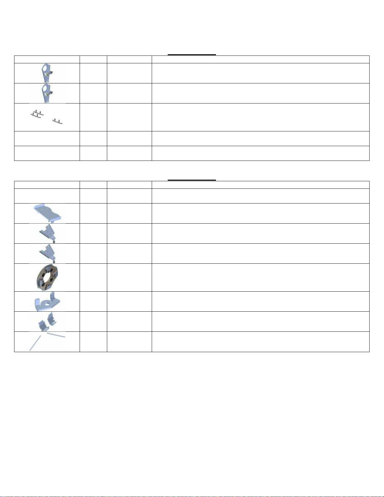
1
00BM
-
006
16x Écrous de roue
16x Wheel nuts
1
00PA
-
243
Assemblage de la plaque d'adaptation ARRIÈRE
REAR Adapter plate assembly
1
00PF
-
246D
Assemblage de la plaque de fixation AVANT DROIT
FRONT RIGHT fixation plate assembly
1
00PF
-
246G
Assemblage de la plaque de fixation AVANT GAUCHE
FRONT LEFT fixation plate assembly
2
04AM
-
020
Adapteurs N/A"
N/A"Adapter
1
99LB
-
005
Ensemble limiteur de braquage
Steering limiter kit
1
99MP
-
002
Repose
-
Pied
Footrest
1
99RE
-
007
Renfort
Reinforcement
19/01/2015
Ver. 1e Les Fabrications TJD inc. 2015
4 / 16
PRÉPARATI
FS
POUR
L’INSTALLATION DES
CHENILLES ARRIÈRE
Placez le véhicule sur une surface plane et de niveau. Puis, au
moyen d’un élévateur ou d’un cric, soulevez l’arrière du véhicule
et stabilisez-le de façon sécuritaire.
Ôtez les roues arrière du véhicule.
Identifiez les deux chenilles arrière et placez-les chacune de leur
côté respectif.
PREPARATION
FOR INSTALLATION OF
REAR TRACKS
Place the vehicle on a flat and even surface. Using a jack or lift,
raise the rear of the vehicle and stabilize it making sure that it is
stable and safe.
Remove the rear wheels from the vehicle.
Identify the left and right rear tracks and place them on the
appropriate side.
AJUSTEMENT DES AMORTISSEURS
ARRIÈRE
Si votre véhicule est équipé d’une suspension avec amortisseurs
ajustables, il est recommandé d’ajuster les amortisseurs à leur point
le plus élevé, tel qu’indiqué dans le guide du propriétaire fourni
par le manufacturier du véhicule.
REAR
SUSPENSION ADJUS
TMENT
If your vehicle is equipped with an adjustable suspension, it is
recommended that the shock absorbers be adjusted to their highest
level as per the instructions supplied by the vehicle’s
manufacturer in the owner’s manual.
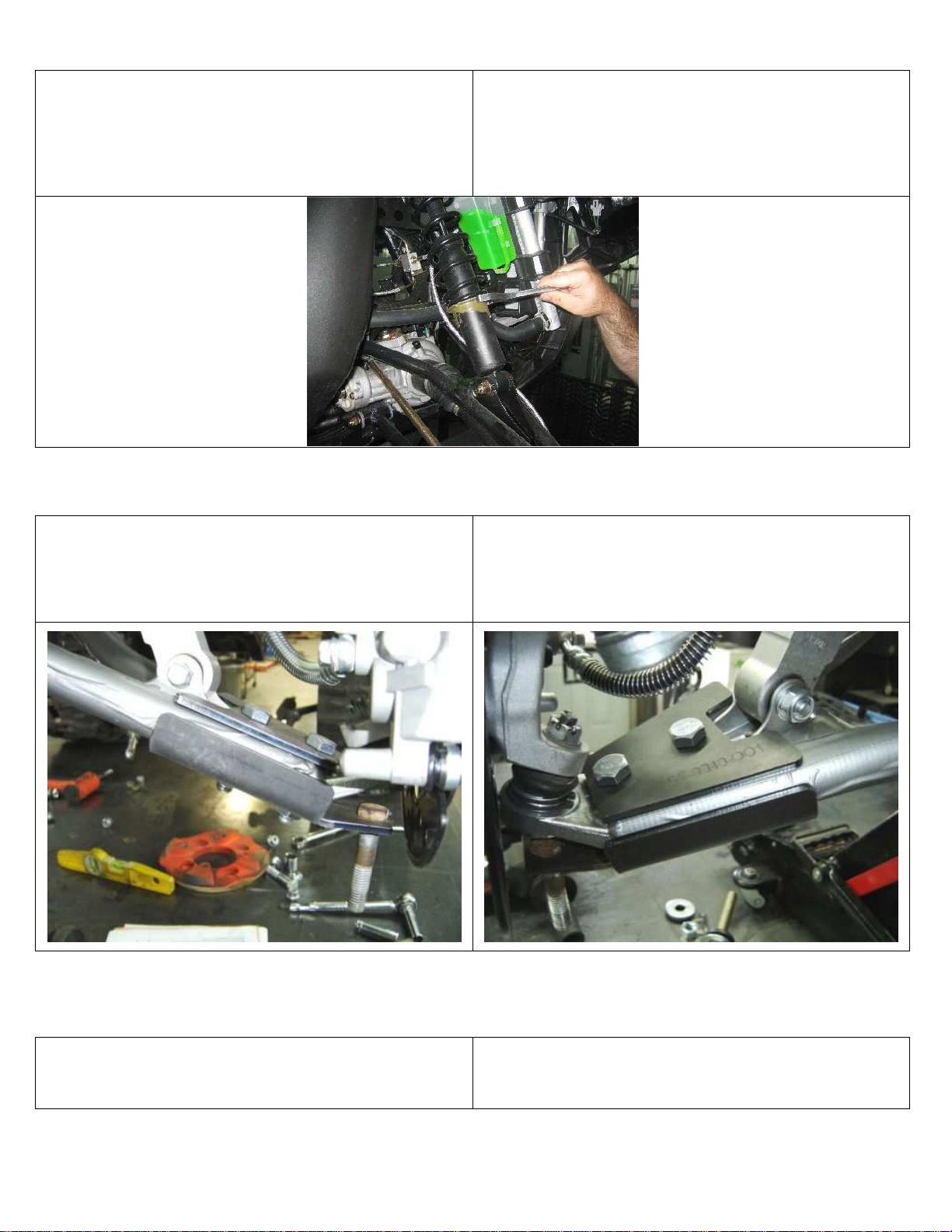
PLAQUE D'ADAPTATION ARRIÈRE / REAR ADAPTER PLATE
00PA-243
Positionnez la plaque sous le véhicule sans la boulonner. Il se
pourrait que vous ayez à percer ou à modifier la plaque protectrice
sous le véhicule et/ou à percer certains trous dans le châssis. Pour
ce faire, servez-vous de la plaque comme d'un guide. Consultez
l'annexe de la 00PA-243 afin d'identifier les pièces nécessaires à la
fixation de la plaque, puis boulonnez la plaque en place.
Position the adapter plate underneath the vehicle without screwing
it in. You may have to drill or modify the protective plate
underneath the vehicle and/or drill holes in the frame as needed. To
do so, use the plate as your guide or template. To view the parts
needed to attach the plate, consult Appendix 00PA-243. Then
firmly screw the plate in place.

19/01/2015
Ver. 1e Les Fabrications TJD inc. 2015
5 / 16
REPOSE-PIED / FOOTREST
99MP-002
S.V.P., consultez l'annexe inclus avec le 99MP
-
002 afin de
procéder à son installation.
Please, refer to the Appendix included with 99MP
-
002 for proper
installation.
RENFORT / REINFORCEMENT
99RE-007
S.V.P., consultez l'annexe inclus avec le 99RE
-
007 afin de
procéder à son installation.
Please, refer to the Appendix
included with 99RE
-
007 for proper
installation.
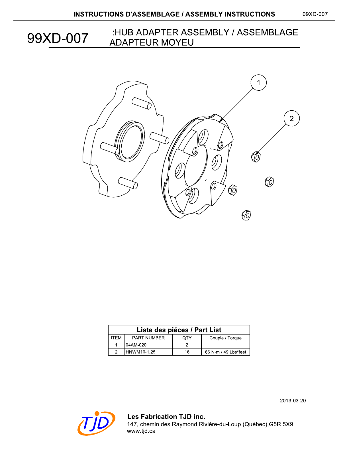
INSTALLATION DES
ADAPT
AT
EURS
DES
MOYEUX ARRIÈRE
Veuillez vous référer à l’annexe 99XD-007 à la fin de ce guide afin
de procéder à l’installation de(s) adaptateur(s) de moyeux requis.
Il est important de respecter le couple de serrage de chaque boulon
et écrou.
IL EST TRÈS IMPORTANT DE RESPECTER LE
COUPLE DE SERRAGE RECOMMANDÉ DANS LE
MANUEL DE VOTRE VÉHICULE POUR LE SERRAGE
DES BOULONS OU DES ÉCROUS QUI SERONT
INSTALLÉS DIRECTEMENT SUR LE MOYEU DU
VÉHICULE.
VOUS DEVEZ AJOUTER DE L’ADHÉSIF À PRISE
MOYENNE SUR TOUS LES BOULONS ET ÉCROUS QUE
VOUS AVEZ À SERRER. (Ex. LOCTITE
®
242
®
)
INSTALLATION OF
THE
REAR HUB ADAPTERS
For the proper installation of the required hub adapter(s), refer to
the appendix 99XD-007. It is important to use the tightening torque
specified for each bolt and nut.
IT IS VERY IMPORTANT TO RESPECT THE
RECOMMENDED TIGHTENING TORQUE INDICATED IN
YOUR VEHICLE’S GUIDE WHEN TIGHTENING THE
BOLTS AND NUTS THAT WILL BE INSTALLED
DIRECTLY ON THE VEHICLE HUB.
A MEDIUM-BOND ADHESIVE MUST BE ADDED
TO ALL BOLTS AND NUTS TO BE TIGHTENED.
(Ex. LOCTITE
®
242
®
)
19/01/2015
Ver. 1e Les Fabrications TJD inc. 2015
6 / 16
INSTALLATION DES CHENILLES ARRIÈRE
Installez les deux (2) vis d’alignement (04BM-003)
contenues dans votre boite 00AC-xxx incluse avec votre
système de chenilles.
INSTALLATION OF REAR TRACKS
Install the two (2) alignment bolts (04BM-003) included in box
00AC-xxx with your track kit.
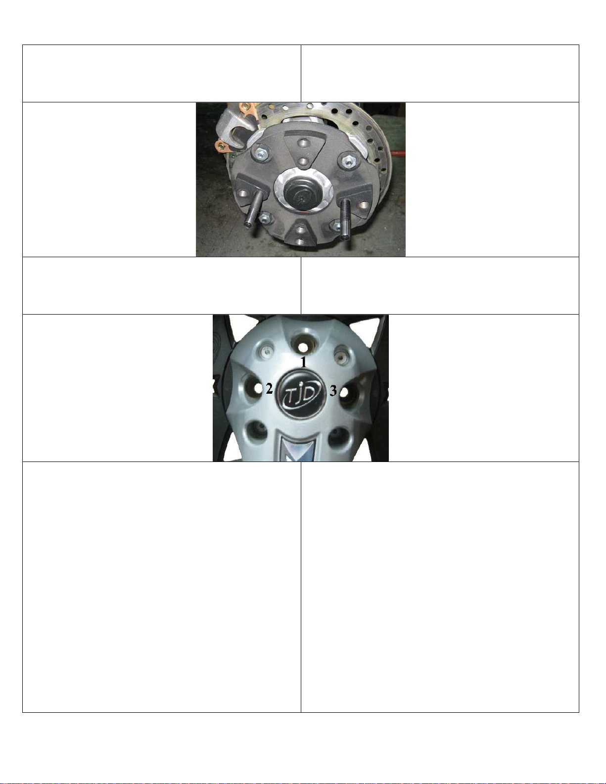
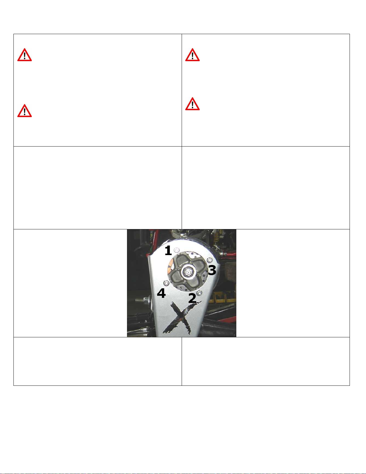
Tout en regardant dans les trous de vissage 1, 2 et 3 du bras
d’aluminium de la structure, alignez le moyeu en tournant le
barbotin, ce qui vous permettra de voir le trou du moyeu.
While looking through the front holes 1, 2 and 3 of the aluminum
structural arm, align the hub by turning the sprocket until you see
the holes in the hub.
Installez la chenille en insérant les vis d’alignement dans les trous
2 et 3 du bras. À l’aide des boulons fournis dans le sac du
MANUEL DE L’UTILISATEUR (02BM-005 ou 02BM-006) fixez
la chenille en vissant le premier boulon à la position 1
(N’OUBLIEZ PAS LE LOCTITE No 242), ne pas serrez ce
boulon, puis retirez la vis d’alignement située à la position 2et
vissez un deuxième boulon (N’OUBLIEZ PAS LE LOCTITE
No 242), ne pas serrez ce boulon, retirez la deuxième vis
d’alignement située à la position 3, puis vissez le troisième boulon
(N’OUBLIEZ PAS LE LOCTITE No 242).
PROCÉDURE DE SERRAGE
1- Débuter à la position 3, prendre soin d’appliquer un
couple de 54.2 N*m (40 lbf*ft) sur ce boulon, poursuivre
à la position 2en suite à la 1en appliquant un couple de
54.2 N*m (40 lbf*ft) à chacune des positions. Pour
installer le quatrième boulon, vous devez faire tourner la
chenille de manière à ce que le moyeu fasse ¼ de tour
dans le sens horaire afin de pouvoir insérer le quatrième
boulon à la position 2 (N’OUBLIEZ PAS LE LOCTITE
No 242), puis vissez-le en prenant soin d’appliquer un
Install the track by inserting the alignment bolts in the holes 2 and
3 in the arm. Using the other bolts included in the USER’S
MANUAL bag (02BM-005 or 02BM006) attach the track by
screwing the first bolt in position 1(DO NOT FORGET TO USE
LOCTITE No 242), don’t tighten this bolt. Then remove the first
alignment bolt in position 2and screw in the second bolt (DO
NOT FORGET TO USE LOCTITE No 242), do not tighten this
bolt. Remove the second alignment bolt in position 3 and screw in
the third bolt (DO NOT FORGET TO USE LOCTITE No 242).
TIGHTNING PROCEDURE
1- Begin at position 3, tighten this bolt at 54.2 N*m (40
lbf*ft) of torque. Then tighten the bolt in position 2with
a torque of 54.2 N*m (40 lbf*ft) and tighten the bolt in
position 1with the same torque of 54.2 N*m (40 lbf*ft).
In order to screw in the fourth bolt, you must first turn the
track clockwise so that the hub makes a ¼ of a turn to be
able to screw in the fourth bolt in position 2 (DO NOT
FORGET TO USE LOCTITE No 242), then screw in
the fourth bolt and tighten it at a torque of 54.2 N*m (40
lbf*ft).
19/01/2015
Ver. 1e Les Fabrications TJD inc. 2015
7 / 16
couple de
54.2 N*m (40 lbf*ft)
.
2- Maintenant serrez le boulon de la position 3avec un
couple de 135.8 N*m (100 lbf*ft), poursuivre à la
position 2en suite à la 1en appliquant un couple de 135.8
N*m (100 lbf*ft) à chacune des positions. Vous devez
maintenant faire tournez la chenille de manière à ce que le
moyeu face ¼ de tour dans le sens antihoraire afin
d’appliquer un couple de 135.8 N*m (100 lbf*ft) au
boulon situé à la position 3.
3- Répétez l’étape 2.
Répétez la procédure pour l’autre chenille.
2
-
Now tighten the bolt in position
3
with a torque of
135.8
N*m (100 lbf*ft), continue with the bolts in position 2
and 1 using the same torque of 135.8 N*m (100
lbf*ft). In order to tighten the last bolt, turn back the
track counterclockwise so that the hub makes a ¼ of a
turn and tighten the bolt 4in position 3with 135.8 N*m
(100 lbf*ft) of torque.
3- Repeat step 3.
Repeat this procedure for the other track.
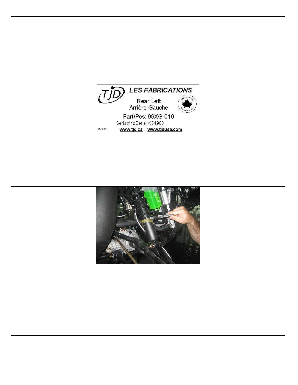
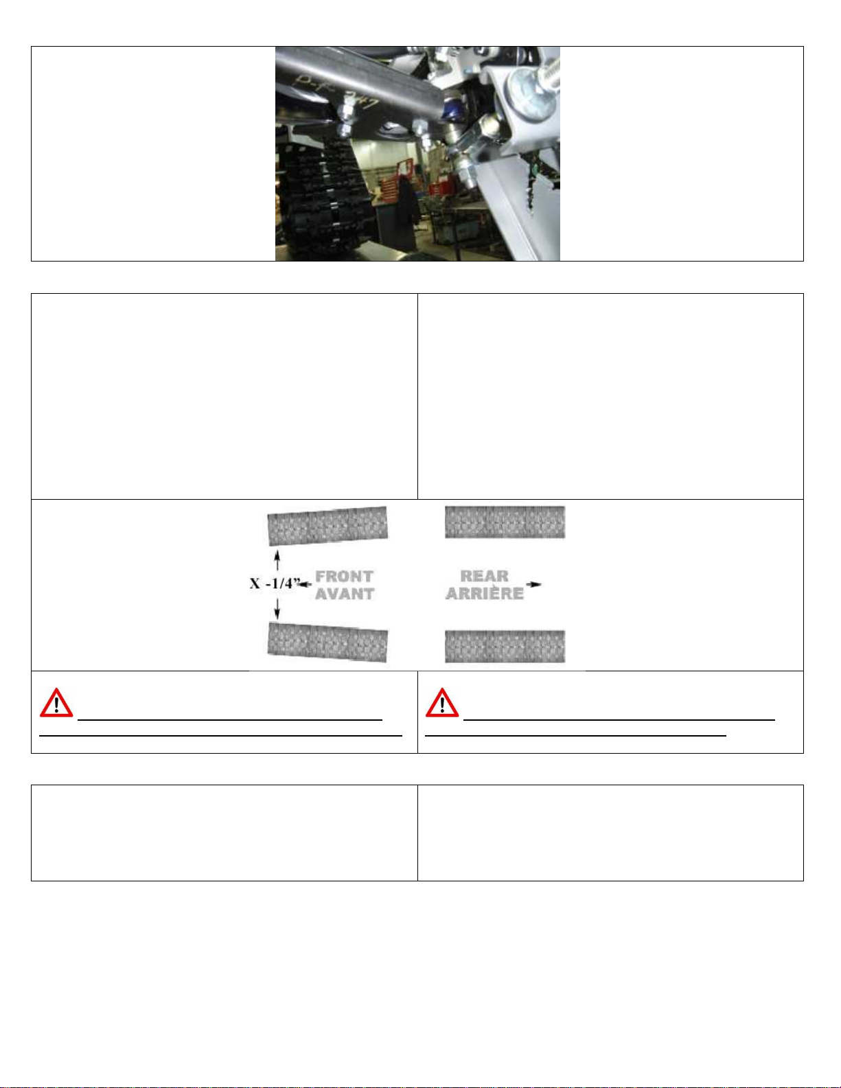
INSTALLATION DES BARRES STABILISATRICE
S
Avant de procéder à l’installation des barres stabilisatrices, il est
important de lubrifier les barres à l’aide d’un fusil à graisser. Une
fois la graisse insérée, faire glisser et tourner le tube afin de
s’assurer que la graisse soie répartie de façon uniforme.
INSTALLATION OF THE STABILIZATION ROD
Prior to the installation of stabilizer bars, it is important to lubricate
the bars with a grease gun. Once the grease is applied, pull and
rotate the tube to ensure that the grease is evenly distributed.
Afin d’installer les barres stabilisatrices arrière, vous devrez retirer
la roue centrale.
Installez la barre stabilisatrice en prenant soin de vous conformer à
l’image ci-dessous et en vous référent à l’annexe inclus avec les
barres stabilisatrices fournis avec votre système de chenilles.
ASSUREZ-VOUS D’APPLIQUER UN COUPLE DE SERRAGE
DE 101.7 N*m (75 lbf*ft).
Réinstallez la roue en prenant soin de mettre du LOCTITE No
242 sur le boulon avant de la visser.
In order to install the stabilization rod, first remove the central
wheel, bolt and bushing.
Carefully install the stabilization rod as shown in the picture below
and by refering you to the annexe included with the stabilization
rods supplied with your tracks system. NOW TIGHTEN THE
BOLT WITH A TORQUE OF 101.7 N*m (75 lbf*ft).
Re-install the wheel making sure to add the LOCTITE No 242 to
the bolt before tightening it.

19/01/2015
Ver. 1e Les Fabrications TJD inc. 2015
8 / 16
XGEN
XTRACK
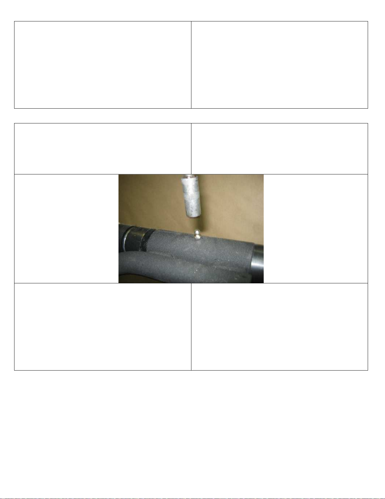
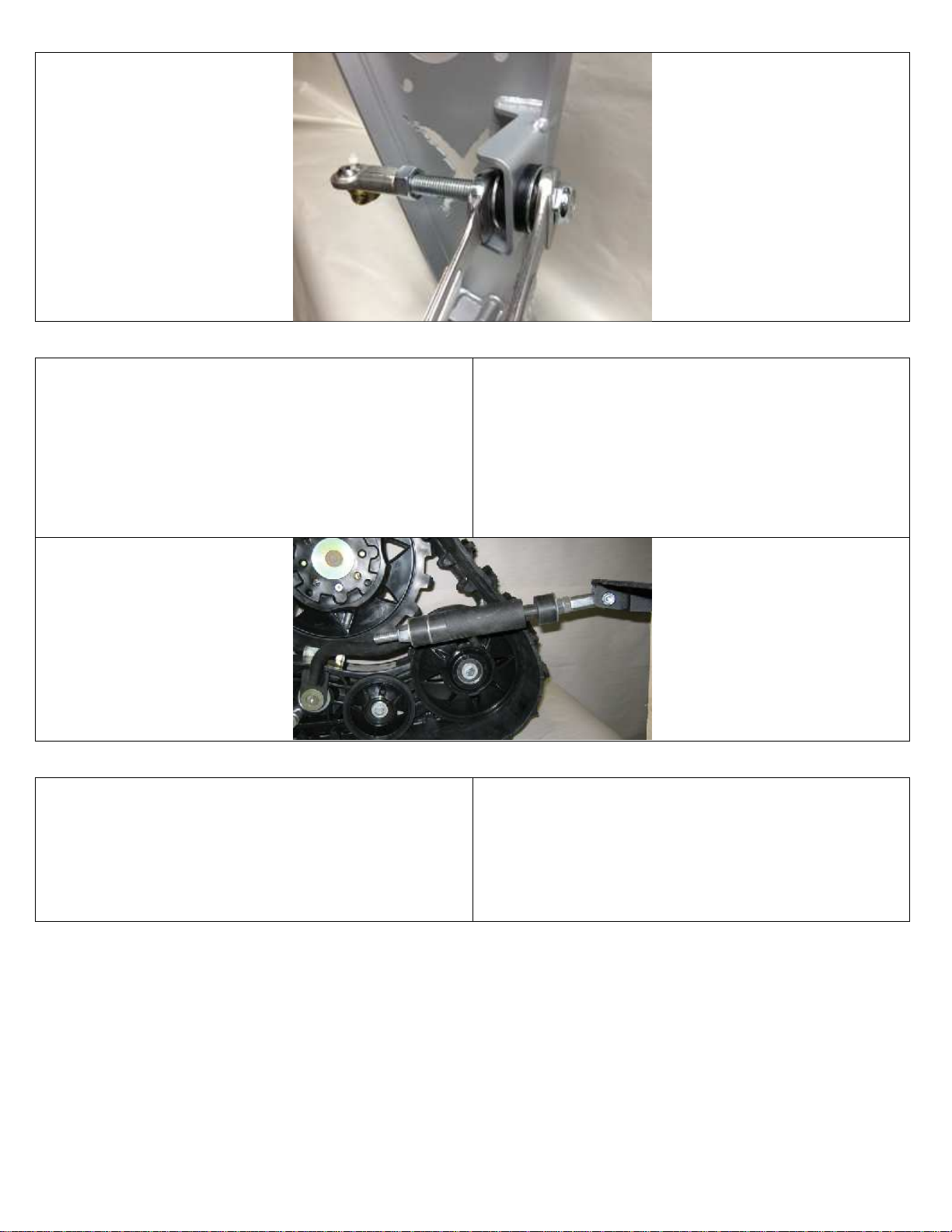
Retirez la vis et les douilles de la rotule à l’extrémité de la barre
puis fixez la barre stabilisatrice à la plaque adaptation en prenant
soin de garder les douilles entre la rotule et le support de la barre.
Si votre support comprend 3 trous de positionnement, utilisez le
trou du centre.
Répétez la procédure pour l’autre barre stabilisatrice.
Remove the bolt and bushing spacers at the end of the rod. Then
attach the stabilization rod to the adapter plate, making sure that
the bushings are placed between the spacers and the rod support. If
your stabilization rod support has three (3) positioning holes, use
the central hole.
Repeat this procedure for the other stabilization rod.
PRÉPARATI
FS POUR
L’INSTALLATION DES
SKIS AVANT
Avec l’aide d’un élévateur ou d’un cric, soulevez l’avant du
véhicule et stabilisez-le de manière sécuritaire.
Retirez les roues avant du véhicule.
Identifiez les structures avant et placez-les de leur côté respectif.
Procédez ensuite à l’installation des lisses sous les skis. (99LI-020)
PREPARATION
FOR THE INSTALLATION
OF
THE
FRONT SKIS
Using a jack or lift, raise the front of the vehicle and stabilize it
making sure that it is stable and safe.
Remove the front wheels.
Identify the right and left front frame and place them on the
appropriate side.
Now install slides under the skis. (99LI-020)

19/01/2015
Ver. 1e Les Fabrications TJD inc. 2015
9 / 16
À l’aide de l’ensemble d’installation (KI-SKI-xxx) fixer les
structures sur les skis en vous référent aux photos ici-bas.
Using the ski's installation kit (KI-SKI-xxx), fix both frames on
each skis by referring you to the pictures below.
19/01/2015
Ver. 1e Les Fabrications TJD inc. 2015
10 / 16
AJUSTEMENT DES
AMORTISSEURS
AVANT
Si votre véhicule est équipé d’une suspension avec amortisseurs
ajustables, il est recommandé d’ajuster les amortisseurs à leur point
le plus élevé, tel qu’indiqué dans le guide du propriétaire fourni
par le manufacturier du véhicule.
FRONT
SUSPENSION ADJUSTMENT
If your vehicle is equipped with an adjustable suspension, it is
recommended that the shock absorbers be adjusted to their highest
level as per the instructions supplied by the vehicle’s
manufacturer in the owner’s manual.
PLAQUES DE FIXATION AVANT / FRONT FIXATION PLATES
00PF-246 (G => Côté Gauche / Left Side || D => Côté Droit / Right Side)
Pour installer les plaques de fixation il se pourrait que vous ayez à
retirer la protection fixée aux triangles de stabilisation. Consultez
l'annexe des 00PF-246 afin de repérer les pièces nécessaires à la
fixation des plaques, puis boulonnez les plaques en place.
In order to install the fixation plates, it may be necessary to remove
the protection attached to the stabilization a-arm. Refer to
Appendix 00PF-246 to identify the parts needed to attach the
fixation plates. Then screw the plates in place.
LIMITEUR DE BRAQUAGE / STEERING LIMITER
99LB-005
S.V.P., consultez l'annexe inclus avec le 99LB
-
005 afin de
procéder à son installation.
Please, refer to the Appendix included with 99LB
-
005 for proper
installation.
19/01/2015
Ver. 1e Les Fabrications TJD inc. 2015
11 / 16
INSTALLATION DES
SKI
A
VANT
IL EST TRÈS IMPORTANT DE RESPECTER LE
COUPLE DE SERRAGE RECOMMANDÉ DANS LE
MANUEL DE VOTRE VÉHICULE POUR LE SERRAGE
DES BOULONS OU DES ÉCROUS QUI SERONT
INSTALLÉS DIRECTEMENT SUR LE MOYEU DU
VÉHICULE.
VOUS DEVEZ AJOUTER DE L’ADHÉSIF À PRISE
MOYENNE SUR TOUS LES BOULONS ET ÉCROUS QUE
VOUS AVEZ À SERRER. (Ex. LOCTITE
®
242
®
)
INSTALLATION OF
THE
FRONT
SKI
IT IS VERY IMPORTANT TO RESPECT THE
RECOMMENDED TIGHTENING TORQUE INDICATED IN
YOUR VEHICLE’S GUIDE WHEN TIGHTENING THE
BOLTS AND NUTS THAT WILL BE INSTALLED
DIRECTLY ON THE VEHICLE HUB.
A MEDIUM-BOND ADHESIVE MUST BE ADDED
TO ALL BOLTS AND NUTS TO BE TIGHTENED.
(Ex. LOCTITE
®
242
®
)
Installez la structure à l’aide des écrous fournis, en respectant
l’ordre 1-2-3-4 illustrée ici-bas. N’OUBLIEZ PAS LE LOCTITE
No 242 avant d’insérer vos écrous. Faite l’installation des écrous
sans appliquer de serrage, une fois les 4 écrous en place, toujours
en débutant à la position 1, appliquer 50% du couple recommandé
par le manufacturier de votre véhicule à chacun des 4 écrous,
recommencer le cycle à la position 1mais cette fois-ci appliquer
100% du couple recommandé.
Répétez la procédure pour l’autre structure.
Install the frame using the nuts supplied by respecting position 1-2-
3-4 like illustrated on picture below. DO NOT FORGET TO
USE LOCTITE No 242 before inserting the nuts. Install the four
nuts without tightening, after that, by starting at position 1, apply
50% of the torque recommended by the manufacturer of your
vehicle for the first pass and 100% for the second pass for each
nuts.
Repeat this procedure for the other track.
Retirez la vis et les douilles de la plaque de fixation puis fixez la
tige stabilisatrice à la plaque de fixation en prenant soin de garder
les douilles coniques de chaque côté de la rotule.
Répétez la procédure pour l’autre tige stabilisatrice.
Remove the bolt and bushing spacers from the fixation plate. Then
attach the stabilization rod to the fixation plate, making sure that
the bushing spacers are placed on each side of the rod end.
Repeat this procedure for the other stabilization rod.
19/01/2015
Ver. 1e Les Fabrications TJD inc. 2015
12 / 16
VALIDATION DE L’ALIGNEMENT
Afin de valider son alignement, placez le véhicule au sol et faites-
le avancer ou reculer en ligne droite sur une distance d’environ 10
pieds (3 m), puis replacez-le à sa position de départ.
Mesurez la distance qui sépare les extrémités avant des chenilles
du devant : notez cette mesure. Mesurez ensuite la distance qui
sépare l’arrière des chenilles du devant : notez cette mesure.
Ajustement recommandé : Parallélisme de 100% ou, de
préférence, avec une fermeture de 1/4 pce (6 mm) à l’avant.
VALIDATION OF ALIGNMENT
To verify the proper alignment of your vehicle, place it on the
ground and advance or backup 10 ft. (3 m) in a straight line then
return to your initial position.
Measure and write down the distance between the front edges of
the front tracks. Then measure and write down the distance
between the back edges of the front tracks.
Recommended adjustment: 100% parallel or, preferably, ¼” (6
mm) closer together in front.
Référez-vous au manuel du véhicule afin d’effectuer
l’ajustement nécessaire pour obtenir la mesure recommandée.
Refer to your vehicle’s manual to make the necessary
adjustments to obtain the recommended alignment.
MISE À NIVEAU DES SKIS AVANT
La mise à niveau recommandée est pré-ajustée en usine. Vous
pouvez tout de même la modifiée selon vos exigences en ajustant
la tige stabilisatrice.
LEVELING OF THE FRONT SKIS
The recommended leveling is pre-adjusted at the factory. You can
modify it according to your needs by adjusting the stabilization
rod.
19/01/2015
Ver. 1e Les Fabrications TJD inc. 2015
13 / 16
MISE À NIVEAU DES CHENILLES ARRIÈRE
Ajustez les chenilles arrière en vissant ou en dévissant l’écrou à
garniture de nylon jusqu’à ce que la pleine longueur des chenilles
soit en contact avec le sol, puis serrez le contre-écrou.
N.B. Si votre support de barre stabilisatrice est à 3 positions, il se
pourrait que vous ayez à changer de point d’attache afin d’avoir un
ajustement optimal.
LEVELING OF
THE
REAR TRACKS
Adjust the rear tracks by screwing or unscrewing the nylon-
covered nut until the tracks are completely in contact with the
ground surface. Then tighten the jam nut.
N.B. If your stabilization rod support has three (3) positions, you
may have to change the attachment point in order to obtain optimal
adjustment.
AJUSTEMENT DE LA TENSION
À l’aide des outils 03OU-001 et 04OU-002 fournis dans votre
boîte 00AC-xxx incluse avec votre système de chenilles et d’un
instrument de mesure de la tension, ajustez le tensionneur situé à
l’extrémité de chacune des chenilles en prenant soin de dévisser le
contre-écrou en premier.
ADJUSTMENT OF THE TENSION
Using the 03OU-001 and 04OU-002 tools, included in box 00AC-
xxx with your track kit, and a pressure measuring tool, adjust the
tensioner located at the end of each track. Make sure to unscrew
the jam nut first.

19/01/2015
Ver. 1e Les Fabrications TJD inc. 2015
14 / 16
Ensuite vissez la tige du tensionneur jusqu’à obtenir la tension
recommandée de 35 lbs / 1 ¼ pces (3 cm)
Adjust the tensioning rod until you obtain the recommended
tension of 35lbs / 1 ¼” (3 cm)
La tension doit être à nouveau vérifiée après les premiers 25 km
que vous aurez parcourus, puis à nouveau après 100 km. Il est
également recommandé de vérifier la tension à chaque début de
saison.
Le maintien d’une bonne tension dans vos chenilles préviendra les
risques de dérapage et de sursaut.
The tension should be checked after 15 miles (25 km) and again
after 62 miles (100 km). It is also recommended that the tension be
checked at the beginning of each season.
Proper maintenance of your track tension will help avoid the risks
of skidding and jolting.

19/01/2015
Ver. 1e Les Fabrications TJD inc. 2015
15 / 16
Une fois la tension ajustée, serrez le contre-écrou puis
pour les modèles XGEN, verrouillez la tension en appuyant la
rondelle excentrique contre le couvercle du tensionneur.
Once the tension has been adjusted, tighten the jam nut
and for XGEN models, lock the tension by applying the
eccentric washer against the tensioner cover.
VALIDATION DE L’INTALLATION
Vous devez maintenant valider la conformité et
l’adéquation de votre installation en effectuant des essais de
braquage et de torsion afin de vous assurer que les chenilles ne
seront jamais en contact avec les ailes, les marche pieds, les
pare-chocs ou toute autre partie de votre véhicule.
VALIDATION OF INSTALLATION
You must now validate that your tracks are properly
installed as required by testing the steering and torsion,
making sure that the tracks will never come into contact with
the fenders, foot rests, bumper or other parts of your vehicle.
19/01/2015
Ver. 1e Les Fabrications TJD inc. 2015
16 / 16
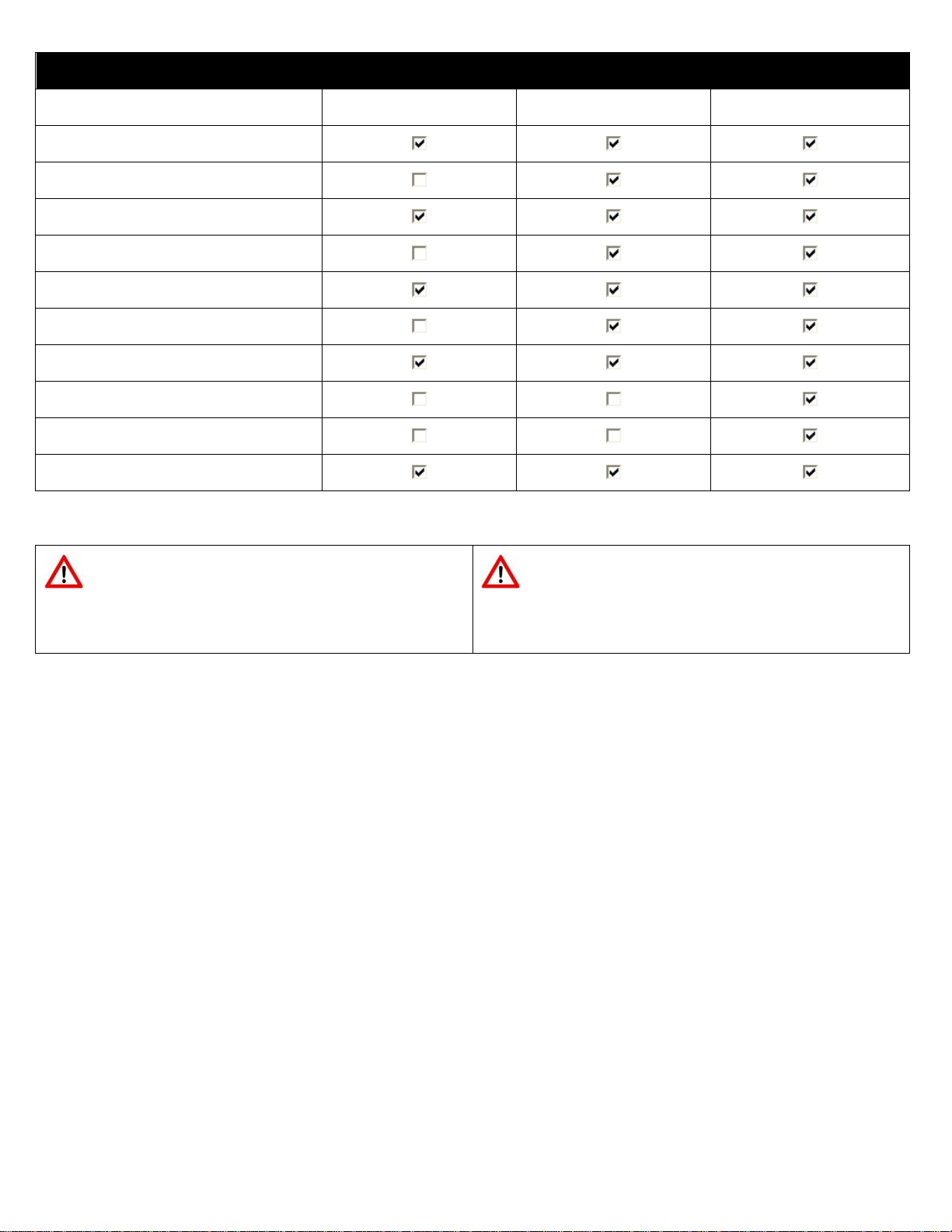
TABLEAU D’ENTRTIEN PRÉVENTIF
PREVENTIVE MAINTENACE SCHEDULE
À vérifier
To be checked
Premiers 25 km (15 miles)
First 25 km (15 miles)
Premiers 100 km (62 miles)
First 100 km (62miles)
Chaque année
Each year
Tension des chenilles
Tracks tension
Roulements des roues et des moyeux
Wheels and hubs bearings
Serrage des boulons et des écrous
Bolts and nuts tightening
Clips de chenilles manquantes
Missing track clips
État du câble arrière (XGEN seulement)
Rear cable status (XGEN only)
Usure des roues et des barbotins
Wear of wheels and sprockets
État général des chenilles
General state of tracks
Graissage les barres stabilisatrices
Stabilizer bars lubrification
Graissage des moyeux
Hubs lubrification
Usure des
lisses de skis
Wear of slides of skis
IL EST IMPORTANT DE LIRE LE
MANUEL DE L’UTILISATEUR AVANT
LA PREMIÈRE RANDONNÉE.
IT IS IMPORTANT TO READ THE
USER’S MANUAL BEFORE YOUR FIRST
RIDE WITH YOUR NEW TRACKS.

0123 41567898 41 7
!"#!"$"#!%$!
&'(('&)*+,-
"./0$1#!%2$!1.%#!3$4"
5+67,8*'69:;
<
='9':>,:-?+=@8,:;
ABCDE
FAFEEGH
FEEGHIC
B
CJCD
I
ACGAKAFELCJD
CM
DFBDLKAEA
ICBICGHAHFE
JNCGDAGBEAOFGDG
FBGAIEPACFHMBGHQ
LAGGEHBLCICBFLGA
ABLABLICAGEEE
RLABCGEAGBHDCGAF
E
JNCGDAGBEAOFGD
S15TUV78685TWX4T863
YZQ[\]^_`]aCbcd_`
C^e^fg]h`ihdijklimn][o
Db_b`bQCp
AmqrkYsos<thss
JburkYsos<vhspp
w
wwxy`[b
JBCKA
FEDCGIAGB
z
hvhvs
`] IJhvY<
z z
z
OBF
vqn
Iqb{i]`]J^ubx^d_
|}~ }
~
~
0124567895889
!0"# !0$
%&'(
)(*+,-./01+2.3+456/712+40809:.2;<7;=+>?;@A.,B*CD4+D&%
EEEFGH2F,5
+IJKL+M'MNOP4+MQQPRL<S+T+MQQPRL<MCP+
M'MNOPK4+RUSPK
%%&'(
0821V12W8X912#Y57082
Z7;=[.+T+O7:\;.?OS
NM4O+]KRLP4^OPR
+)MR
__+]/+T+)%+<A3`a..G
_J]bR*D
This manual suits for next models
1


