TKB Home TZ79 User manual

-1-
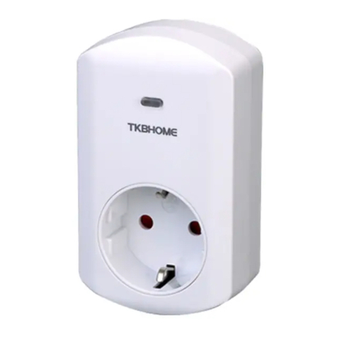
This insert switch module in a transceiver which is a Z-Wave enabled device
and is fully compatible with any Z-Wave enabled network. Z-Wave enabled devices
displaying the Z-Wave logo can also be used with it regardless of the manufacturer,
and ours can also be used in other manufacturer's Z-Wave enabled networks.
Remote On/Off control of the connected load is possible with other manufacturer's
wireless controller. Each switch is designed to act as a repeater. Repeaters
will re-transmit the RF signal to ensure that the signal is received by its intended
destination by routing the signal around obstacles and radio dead spots.
This plug-in On/Off switch is able to detect current wattage (5~3000W) and overload
wattage(3010~3300W) of connected lights or appliances. When detecting overload
state, the Switch will be disabled and its On/Off button will be lockout of which LED
will flash quickly. However, unplug and re-connect the switch will reset its overload
condition to normal status.
The product supports Over The Air(OTA) feature for the products firmware upgrade.
-4-
TZ79-V2.0-2016 .3.6
A Z-Wave network can integrate devices of various classes made by different manufacturers.
The TZ78 can be incorporated into existing Z-Wave networks. The TZ78 module can be used
to carry out inclusion,association, or exclusion.
Minimum 40m in door 70m outdoor line of sight
AC110V~230V 50Hz/60Hz
868.4MHz(EU),908.4MHZ(US),921.4MHz(AU),869MHz(RU)
3000W,(1500W for US)
TZ79 Insert switch module
Note: This module must be“Included in the network”,and suitable for where it will be
permanently installed. The proper operation of this node in the mesh network is
dependent on it knowing it’s location with respect to other nodes. You can not "test
bench" configure this module, then install.
Wiring diagram
L
L
NO1
N N
S
In the front casing, there is an On/Off button with LED indicator which is used to
toggle switch on and off or carry out inclusion, exclusion, reset or association.
When first power is applied, its LED flashes on and off alternately and repeatedly
at 1-second intervals. It implies that it has not been assigned a node ID and can not
work with Z-Wave enabled devices.
The table below lists an operation summary of basic Z-Wave functions. Please
TM
refer to the instructions for your Z-Wave certificated primary controller to
access the setup function, and to include/exclude/associate devices.
L: Line voltage input
NO1: Switched load output
N: Line neutral
S: Connect to wall switch input
SWITCH
Load
LL
NN
S
NO1
Relay
Interoperability with Z-WAVE devices
L
N

-3-
-2-
Product size (mm)
Set the On/Off
switch of the load
attached to on
Z-Wave Configuration
Watt Meter
Report period
KWH Meter
Report period
Threshold of Watt
for load caution
Threshold of KWH
for load caution
watt Meter Report Period:
If the setting is configured for 1 hour (set value =720), the TZ79 will report its instant power consumption every 1 hour
to Z-Wave Controller. The maximum interval to report its instant power consumption is 45 hours (5s*32767/3600
=45hr).
KWH Meter Report Period:
If the setting is configured for 1hour (set value =6), the TZ79 will report its Accumulated Power Consumption (KW/h)
every 1 hour to Z-Wave controller. The maximum interval to report its Accumulated Power Consumption (KW/h) is 227.55
days (10min*32767/1440=227.55 days).
Threshold of Watt for Load Caution:
In the above form, when the value is 3000, if relay1 load by below 3000 watt turned into more than 3000 watt,
will immediately send the instantaneous load w value to Group 1. The maximum set scope is 3000 watt, minimum
scale value of 10 watt, the default value is 3000 watt.
Threshold of KWH for Load Caution:
In the above form, when the value of 10000, when the accumulation of relay1 consumed power more than 10000 KWH,
will immediately send the accumulation of current consumed power to group1 . Maximum can set range t0 10000 KWH,
minimum scale value is 1 KWH, the default value is 0, 0 not have load caution.
Memory function:
Stated in the above form, TZ79 by default value is 1, when the value is 0, TZ79 memory function not open; When
the value is 1, open TZ79 memory function.
Change the state of indicatorlight:
Stated in the above form, the default value is 1, when the value of TZ79 is 0, socket LED indicator will be on when
the light status is " on "; When set to 1 , the socket LED indicator will be off when the light status is " on ".
No node ID The Z-Wave Controller does not allocate
a node ID to the Switch. 1-second on, 1-second off
1. Have Z-Wave Controller entered inclusion
mode.
2. Pressing On/Off button three times within
1.5 seconds will enter inclusion mode.
1. Have Z-Wave Controller entered exclusion
mode.
2. Pressing On/Off button three times within
1.5 seconds will enter exclusion mode.
Node ID has been excluded.
1. Pressing On/Off button three times within
1.5 seconds will enter inclusion mode.
2. Within 5 second, press On/Off button again
for 1 seconds until LED is off.
3. ID is excluded
1. Have Z-Wave Controller entered association
mode.
Or Pressing On/Off button three times within
1.5 seconds will enter association mode
2. There are two groups for the switch
Each group can associate max five devices.
※Including a node ID allocated by Z-Wave controller means Add. Excluding a node ID allocated by
Z-Wave controller means remove.
※ Failed or success in including/excluding the node ID can be viewed from the Z-Wave controller.
※ Association:it can be associated by Z-Wave devices with association
※ Use the"Reset" procedure only in the event that the network primary controller is missing or
otherwise inoperable
※ The group identifier is "Group 1 ".
Association group info report command class
Profile:General lifeline (Profile MSB=0x00,Profile LSB=0x01)
Association group name report command class
Group 1 :lifeline
7Edge or Pulse mode
or Edge-Toggle mode 1 1-3 3
1:Edge mode
2:Pulse mode
3:Edge-togle mode
0
0-10000
The switch isn’t working
and LED off
1.The switch is not
connected to the power
2. The switch is out of
order
1. Check power
connections
2. Don't open up the
switch and send it
to repair.
The swich LED illuminating, but can
not control the On/Off switch of the
load attached
Check if the load plugged
into the switch has its own
On/Off switch
The switch LED illuminating,but the
controler can not control the switch
1. Not carry out association
2. Frequency interference
1. Carry out association
2. Wait for a while to re-try
LED keep flashing, but cannot
control
Overload occurs Remove the load attached
or check max.
load cannot exceed
3010W 3300W~
Other TKB Home Switch manuals
Popular Switch manuals by other brands
THOMSON
THOMSON Grass Valley TRITON TTN-BTS-0808/140 installation manual
Siemens
Siemens SIMATIC NET RUGGEDCOM M2100 installation manual
ZyXEL Communications
ZyXEL Communications MES3500 Series user guide

Aukey
Aukey CB-C55 user manual
Belkin
Belkin F5U261 user manual
Key Digital
Key Digital KD-CSW2X1 Specifications

