TKOKO M-5060 User manual

Public address systems
& Commercial sound systems
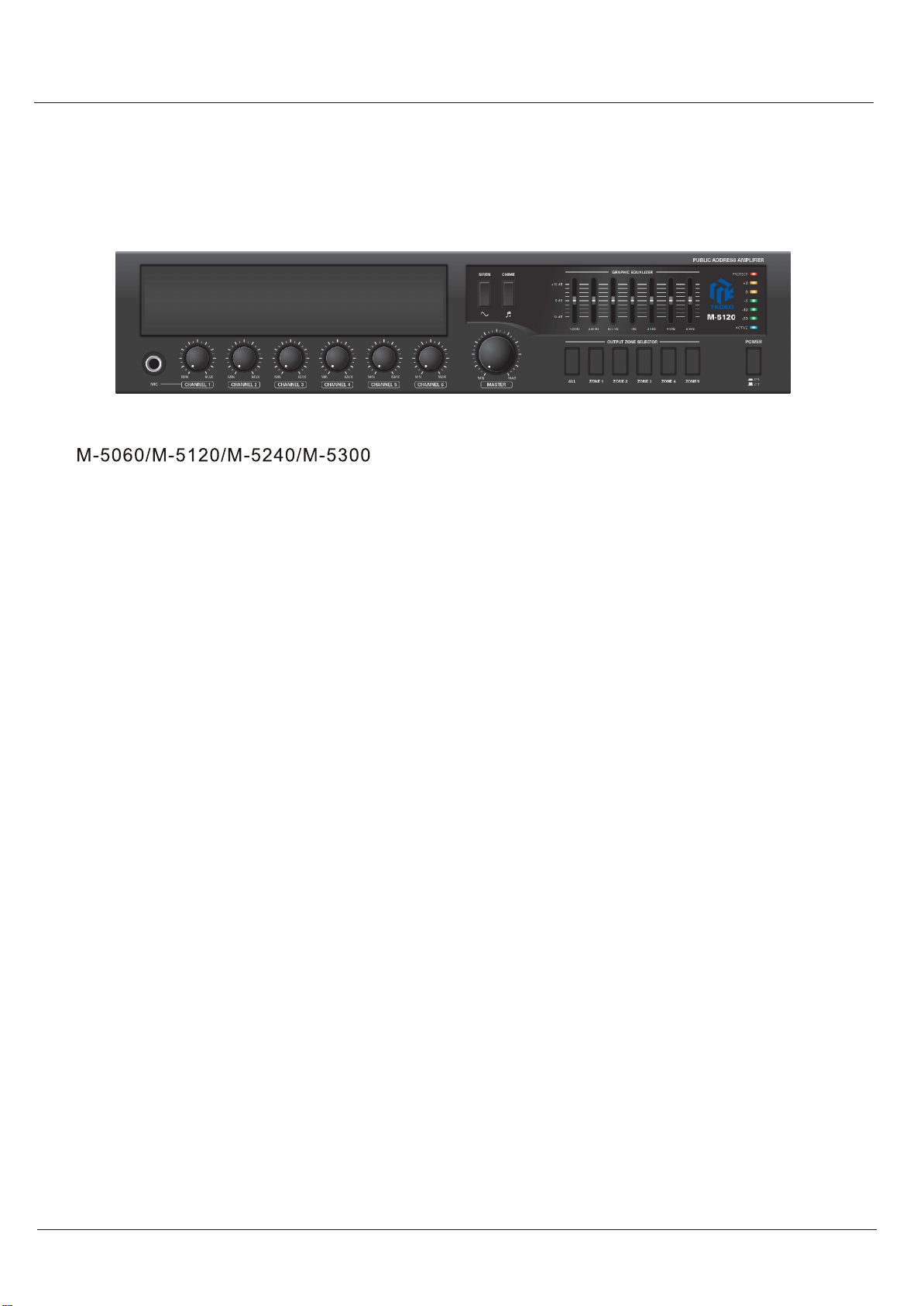
M-5060, 5120, 5240, 5300
Mixer Amplifier
www.t-koko.com

WARNING
TO PREVENT FIRE OR SHOCK HAZARD.DO NOT USE THIS PLUG WITH AN EXTENSION CORD, RECEPTACLE
OR OTHER OUTLET UNLESS THE BLADES CAN BE FULLY INSERTED TO PREVENT BLADE EXPOSURE.
TO PREVENT FIRE OR SHOCK HAZARD.DO NOT EXPOSE THIS APPLIANCE TO RAIN OR MOISTURE.
TO PREVENT ELECTRIC SHOCK.MATCH WIDE BLADE PLUG TO WIDE SLOT FULLY INSERT.
This lightning flash with arrow
Head symbol within an equi-
Lateral triangle,isintendedto
Alert the user to the presence
Of uninsulated "dangerous
Voltage" within the product's
Enclosure that may be of
Sufficient magnitude to
Constitute a risk of electric
Shock to persons
Warning:to reduce the risk of
Electric shock,do not remove
Cover(or back) no user-
Serviceable parts inside.refer
Serving to qualified service
Personnel
The exclamation point within
An equilateral triangle is
Intended to alert the user to
The presence of important
Operating and maintenance
(servicing) instructions in
The literature accompanying
The appliance
12.Use only with the cart, stand, tripod, bracket, or table specified by the manufa-
cturer or sold with the apparatus, when acart is used, be cautious when moving the
cart apparatus combination to avoid in jury from tip over
1.Read these instructions
2.Keep these instructions
3.Heed all warnings
4.Follow all instructions
5.Do not use this apparatus near water
6.Clean only with dry cloth
7.Do not block any ventilation openings.Install in accordance with the manufacturer instructions's
8.Do not install near any heat sources such as radiators heat registers, stoves or other apparatus
(including amplifiers) that produce heat
9.Do not defeat the safety purpose of the polarized or grounding type plug.Polarized plug has two
blades with one wider than the other .A grounding type plug has two blades and a third grounding
prong. The wide blade or the third prong are provided for your safety.If the provided plug does not
fit into your outlet, consult an electrician for replacement of the obsolete outlet
10.Ptest the power cord from being walked on or pinched particularly at the plugs convenience
receptacles and at the point where they exit from the apparatus
11.Only use attachments/accessories specified by the manufacturer
16.Use caution to prevent electric shock, match wide blade plug to wide slot, fully inserted
13.Unplug the apparatus during lightening sort or when unused for long periods of time
14.Refer all servicing to qualified personnel. Serving is required when the apparatus has been damaged
in anyway such as power supply cord or plug is damaged liquid has been spilled or objects have fallen
into the apparatus has been exposed to rain or moisture does not operate normally or has been dropped
15.This appliance shall not be exposed to dripping or splashing water and that no object filled with liquid
such as vases shall be placed on the apparatus
17.Please keep a good ventilation environment around the entire unit
IMPORTANT SAFETY INSTRUCTION

11
Tableof Contents
Features .............................................................................................. 3
Front Panel Controls ........................................................................... 4
Rear Panel Controls ............................................................................ 5
Setup ...................................................................................................6
Wiring Guide ...................................................................................... .7
Connections ....................................................................................... 8
Operations ........................................................................................ 11
Applications ......................................................................................15
Block diagram ..................................................................................16
Specifications ....................................................................................17
Introduction......................................................................................... 2
Table of Contents
M-5060/M-5120/M-5240/M-5300
22
Introduction
Introduction
Congratulation and thank you for purchasing the M series, amulti-function commercial amplifier.
These amplifiers are designed to provide abig impact in sound reproduction and to produce the
best and highest quality audio at an affordable price. We wish you great enjoyment and satisfac-
tion when using your amplifier, whether you are an installation, or reinforcement engineer.
Unpacking and Installation
Although it is neither complicated to install nor difficult to operate your amplifier, afew minutes of
your time is required to read this manual for aproperly wired installation and becoming familiar
with its features and how to use them. Please take agreat care may be needed when moving
your set and are required if it ever becomes necessary to return your set for service. Never place
the unit near radiator, in front of heating vents, to direct sun light, in excessive humid or dusty
location to avoid damages and to guaranty along reliable use.
Connect your unit with the system components according to the description on the following pages.
Welcome
M-5060/M-5120/M-5240/M-5300

33
Features
Features
The M system are comprehensive, all-in-one mixer-amplifier solutions for commercial
and industrial applications.These low-cost units provide all necessary features in asimple build-
ing-block format.
*Six microphone or line inputs with 1/4-inch phone,XLR and RCA jacks.
*Acceptable wide range input level.
*One telephone paging input with EURO block terminal.
*Phantom power for MIC channel 1and 2.
*Three layer priority muting.
*Built in four kinds user selectable pre-announce chime.
*60watts(M-5060),120watts(M-5120) ,240watts(M-5240),300watts(M-5300) power output.
*Advanced protection system includes current limiting, over current and thermal protection.
*Desktop and 19-inches rack mountable type.
*Seven band graphic equalizer.
*Expendable by adding audio mixer and power amplifier with LINK and PRE-AMP terminal.
*Low distortion and low noise level.
*Compact size and lightweight.
*ldeal for commercial and industrial use.
M-5060/M-5120/M-5240/M-5300
44
Controls
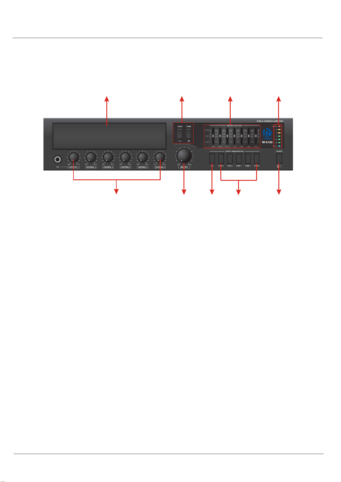
Front Panel Controls
1. Bay for adding optional music source (CD player with AM/FM Tuner,or MP3 player).
2. Graphic equalizer control (125Hz/250Hz/500Hz/1kHz/2kHz/4kHz/8kHz).
3. Indicators(Protection/Output level/Power).
4. Input channel volume controls.
5. Master volume control.
6. All speaker zone output selector.
7. Individual speaker zone output selector.
8. Power switch
9.Evacuation siren and pre annuncement Chime switch
1
4568
7
239
M-5060/M-5120/M-5240/M-5300
55
Controls
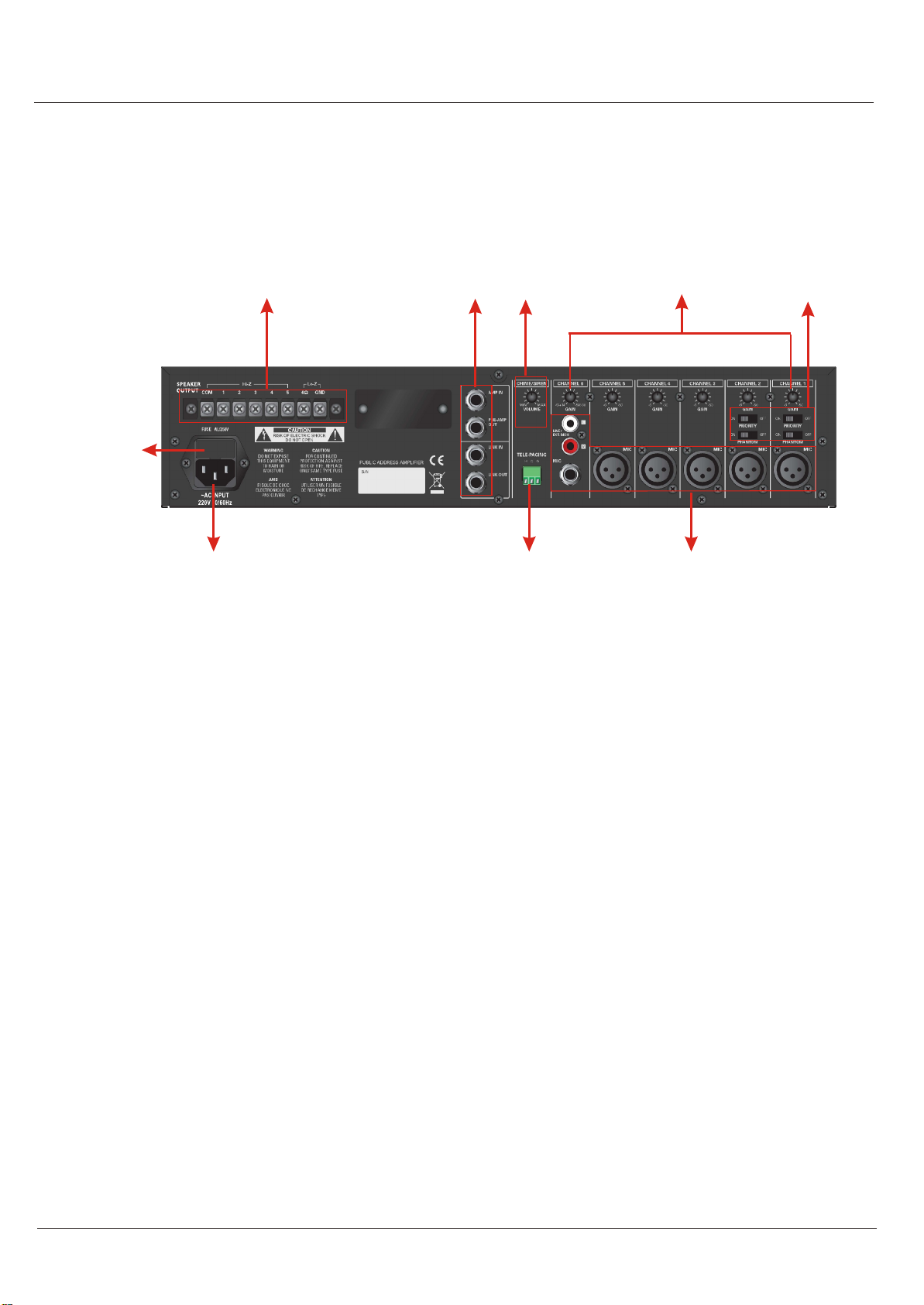
Rear Panel Controls
1. ACfuse.
2. Expansion ports ( AMP-IN/AMP-OUT/LINK-IN/LINK-OUT ).
3. Pre-announce chime/Siren level control
4. Gain controls for variable input level.
5. Phantom power and priority control switches.
6. Signal input connectors.
7. Telephone paging input connector.
8. Speaker outputs connector ( 4-ohm, selectable 25V, 70V and 100V ).
9. AC power socket
1
2345
6
7
8
9
2
M-5060/M-5120/M-5240/M-5300

66
Setup
Setup
Installation
CAUTION: Before you begin, make sure your mixer-amplifier is disconnected from the power
source, with the power switch in the OFF position and all level controls turned completely
down(counterclockwise)
You may stack mixer-amplifiers without using acabinet or you may place asingle mixer-amplifier
on asurface with 12-inches (about 30cm) of air space around the unit for convection cooling.
When using an equipment rack, do not mount units directly on top of each other. Allow 2U be-
tween units for convection cooling. The side walls of the rack should be aminimum of 2-inches
(about 5cm) away from the amplifier sides, and the back of the rack should be aminimum of
4-inches (about 10cm) from the mixer-amplifier rear panel.
Installation
1. Locate the two rack ears and six rack-ear screws supplied.
2. Place arack-ear flush with the right front of the chassis.
3. Insert ascrew into the bottom hole of the rack-ear and chassis. Screw it in.
4. Insert ascrew into the mid hole of the rack-ear and chassis. Screw it in
5. Insert ascrew into the top hole of the rack-ear and chassis. Screw it in.
6. Repeat steps 2to 5for the left side of the chassis.
7. Remove the four legs from bottom of unit.
8. Please refer to Figure .
[ How to connect rack ears ]
M-5060/M-5120/M-5240/M-5300

77
Setups
Wiring Guide
Choose input wire and connectors
TKOKO recommends using pre-built or professionally wired balanced line,22 to 24 gauge cables.
Figure shows connector pin assignments for wiring .The RCA input connections can also be used
for unbalanced inputs.
M-5060/M-5120/M-5240/M-5300
88
Setups
Choose input wire and connectors
For the amplifier output connectors,TKOKO recommends using pre-built or professionally wired,
high-quality, and heavy gauge speaker wires.You may use screw terminal for your output connec-
tors.To prevent the possibility of short-circuits, wrap or otherwise insulate exposed loudspeaker
cable connectors.
Using the guidelines below, select the appropriate size wire based on the distance from amplifier
to speaker. The wire sizes apply to the 4-ohm tap.
Distance Wire Size
Up to 25 ft. 16 AWG
26~40 ft. 14 AWG
41~60 ft. 12 AWG
61~100 ft. 10 AWG
101~150 ft. 8 AWG
151~200 ft. 6 AWG
NOTE: Custom wiring shoule only be performed by qualified personnel. Class 2wiring is re-
quired.
CAUTION: Never use shielded cable for output power wiring
Figure shows connector pin assignments for wiring
[Connection to speakers illustration ]
Hi-Z
Lo-Z
M-5060/M-5120/M-5240/M-5300

99
Setups
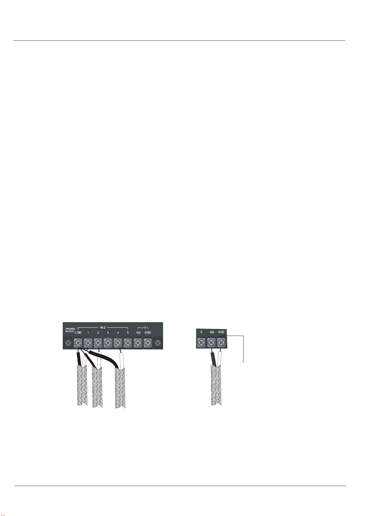
Speaker connection is shown in Figure.
[How to connect speakers ]
CAUTION :Never use both the Low-Z(4 ohms)and Hi-Z(25V, 70V and 100V) terminals at the
same time
[Wrong connection ]
-
+
-
+
-
+
-
+
-
+
-
+
-
+
-
+
4
88
2
M-5060/M-5120/M-5240/M-5300
1010
Setups
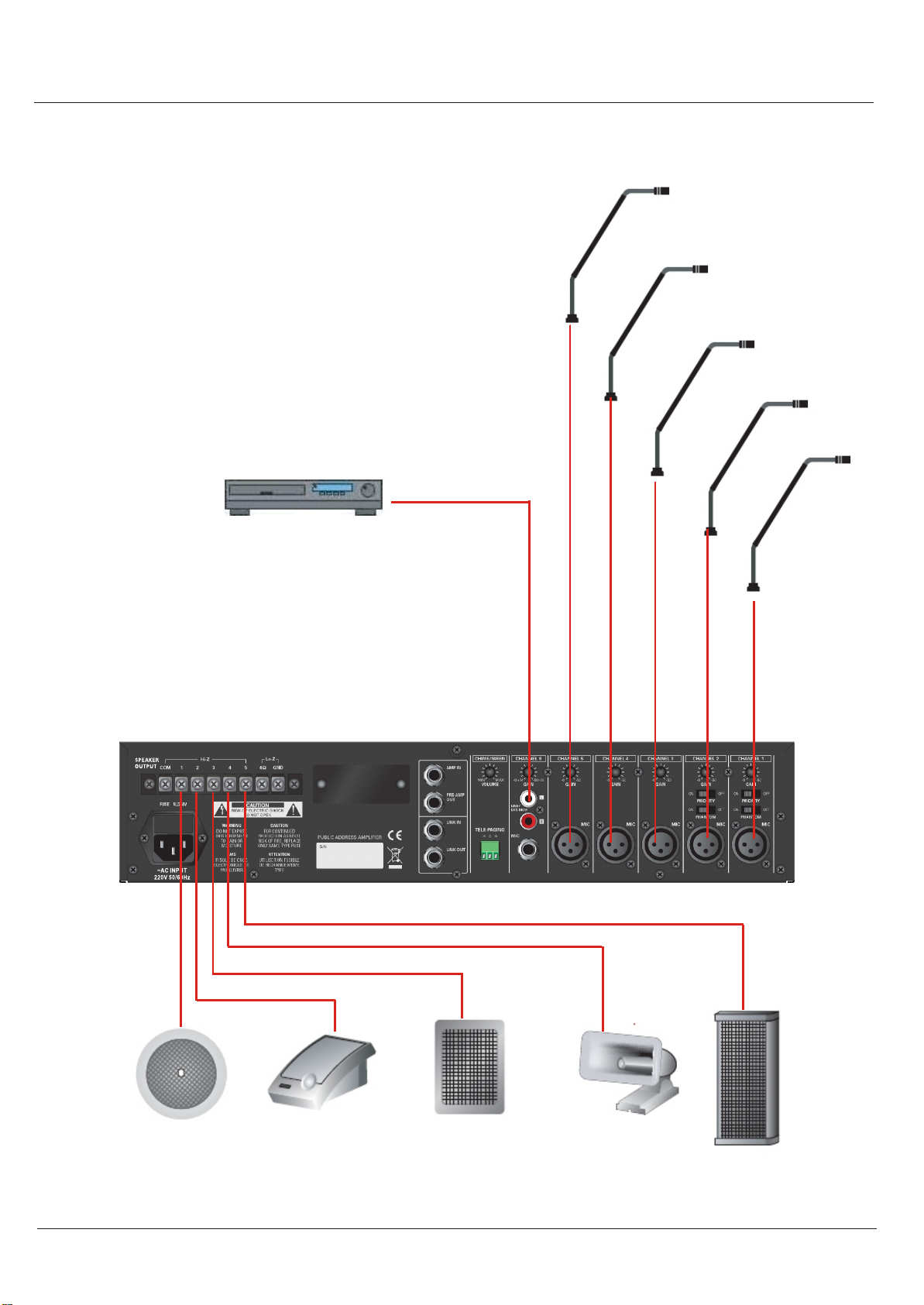
Typical input and output wiring is shown in Figure.
2
M-5060/M-5120/M-5240/M-5300
Operations
1111
Operation
[Expansion M series ]
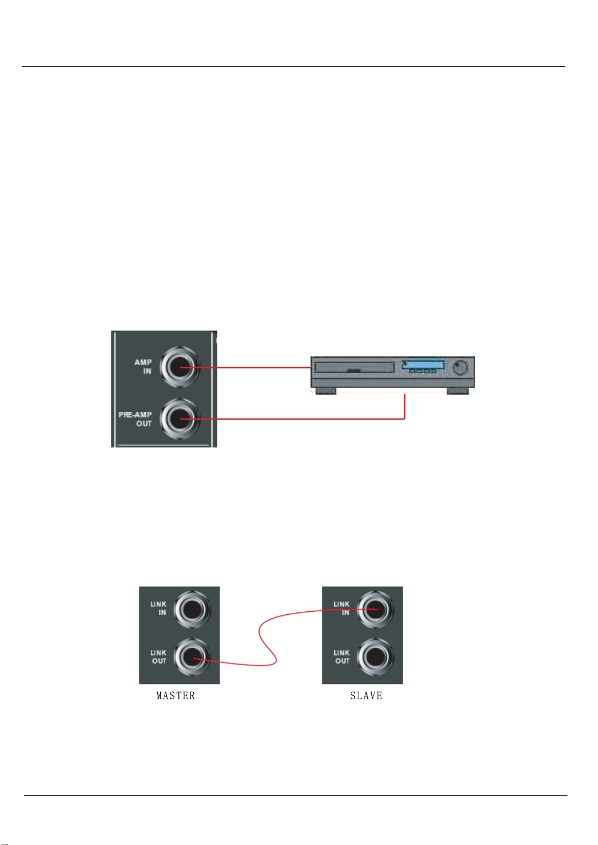
External equipments connection
By connecting a signal processor such as an equalizer or limiter between the mixer section (PR
E-AMP OUT) and the power amplifier section(AMP IN) of the M series, signals can be tailored
for desired sound output.
NOTE
Inserting a 1/4-inch phone plug into AMP IN terminal disconnects internal power amplifier section
from the mixer section.
[ External equipments connection ]
Sound Processor
Expansion M series
M series mixer-amplifier allows expansion with LINK IN and LINK OUT connector.
If you need more input and output, just this function allows you can do that.
This function affect which signals are heard when another mixer or M series mixer-amplifier are
wired to the mixer-amplifier.
M-5060/M-5120/M-5240/M-5300
1212
Operation
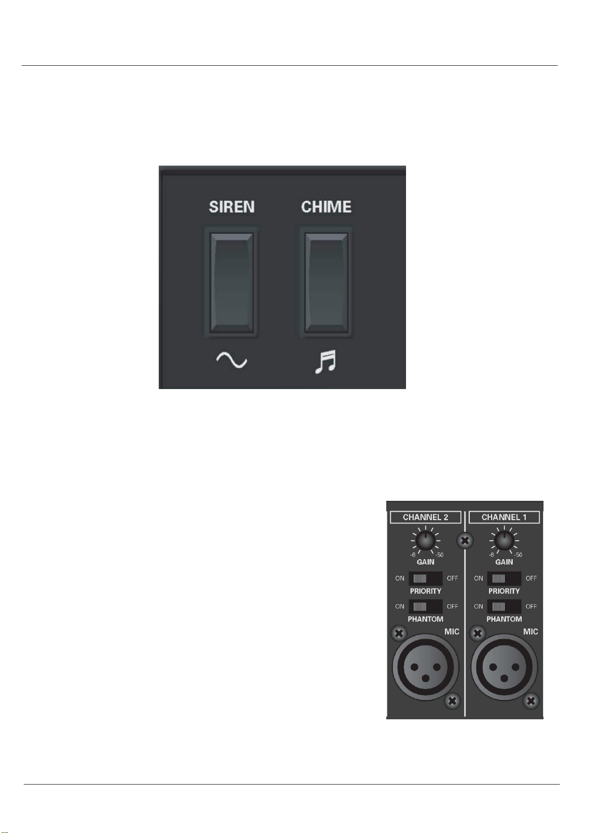
Preannounce chime
M series mixer-amplifier supply user selectable 2 kinds of preannounce chime.
The way of set up is same as follow figure .
[ Chime selection ]
Priority
This function allows talk over for MIC channel 1 and 2.
All other input signals are muted when this function is activated
during stay "ON" position.
Figure shows the priority switches and its "ON" and "OFF"
Positions.
M series mixer-amplifier supply DC + 15 Volts phantom power to
use condenser microphone with MIC 1 and 2 channels.
Figure shows the phantom power switches and its "ON" and
"OFF" positions.
Phantom power
[ Phantom and Priority ]
M-5060/M-5120/M-5240/M-5300
1313
Operation
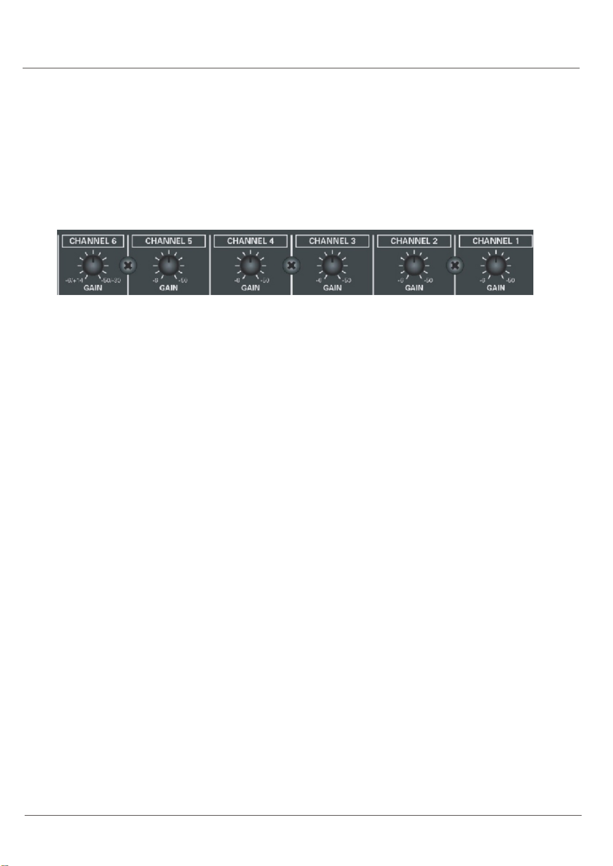
Signal input gain control
M series mixer-amplifier can accept variable and wide range input signal with trim pot.
Adjusts the trim pot in a range of 44dB to accept variabe external equipments.
Figure 3.6 shows detail input sensitivities.
[ Acceptable input sensitivity per each channels ]
M series mixer-amplifier has three level priority mute function. When higher level source is acti-
vated,other input signals are muted except same priority level source.
CH3~CH6>CH1~CH2, Chime>Telephone paging.
Priority Control
M-5060/M-5120/M-5240/M-5300
Connection
Input
XLR jack Stereo 6.3mm jack(CH6) RCA (CH6) for both microphone in and line in
CH1~CH6 input sensitivity can be adjusted.
Output
4Ù constant impedance output, connect to ground independently.
Rated power output of 5 zones; Each zone can be controlled by the switch; Common
grounding.
For rated output, different voltage output can be selected by different line connection:
100V 70V 25V default 100V output for optional.
LOAD SPECIFICATION
M-5060 4Ù/15.5V10.4Ù/25V 81Ù/70V 167Ù/100V
M-5120 4Ù/22V5.2Ù/25V 40.8Ù/70V 83Ù/100V
M-5240 4Ù/31V2.6Ù/25V 20.4Ù/70V 42Ù/100V
M-5300 4Ù/34.6V2Ù/25V 46.3Ù/70V 33.3Ù/100V
Optional Rated output
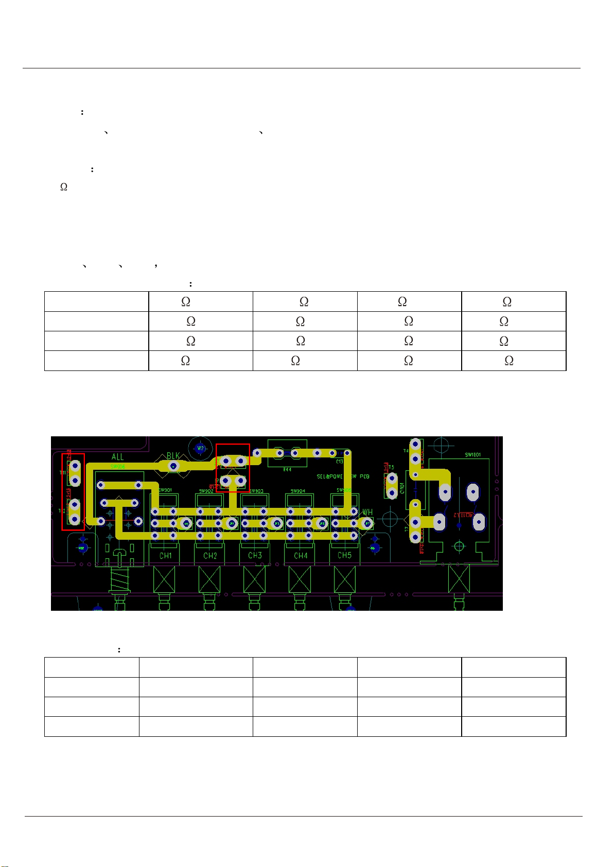
Inner Connection Diagram
Connection
PCB Terminal T10 T12 T11 T13
100V RED BLUE GREEN BLACK
70V GREEN RED BLUE BLACK
25V BLUE GREEN RED BLACK
Operation
M-5060/M-5120/M-5240/M-5300
1414
1515
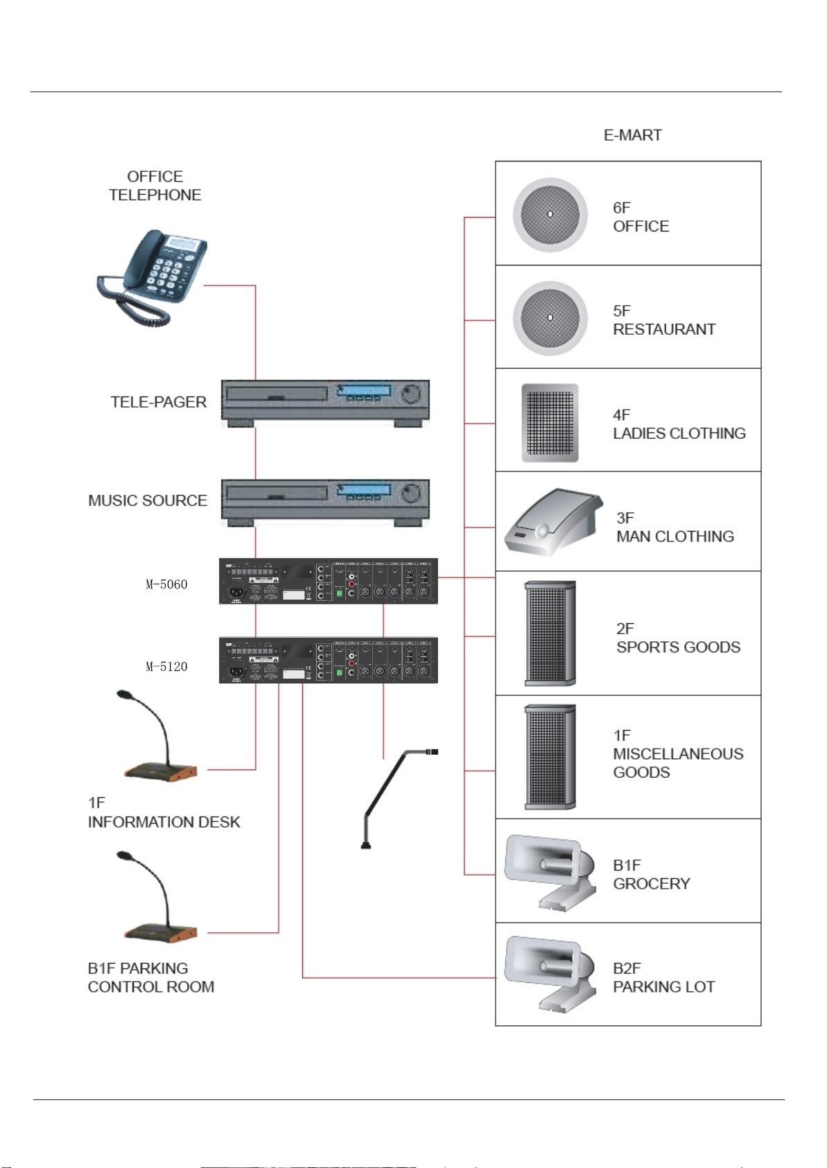
Application
M-5120
M-5060
Application
2
2
M-5060/M-5120/M-5240/M-5300
1616
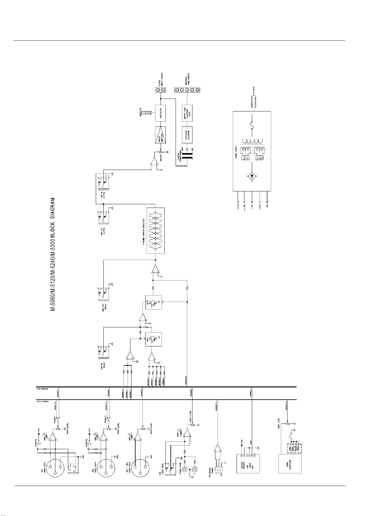
Block diagram
Block diagram
M-5060/M-5120/M-5240/M-5300
1717
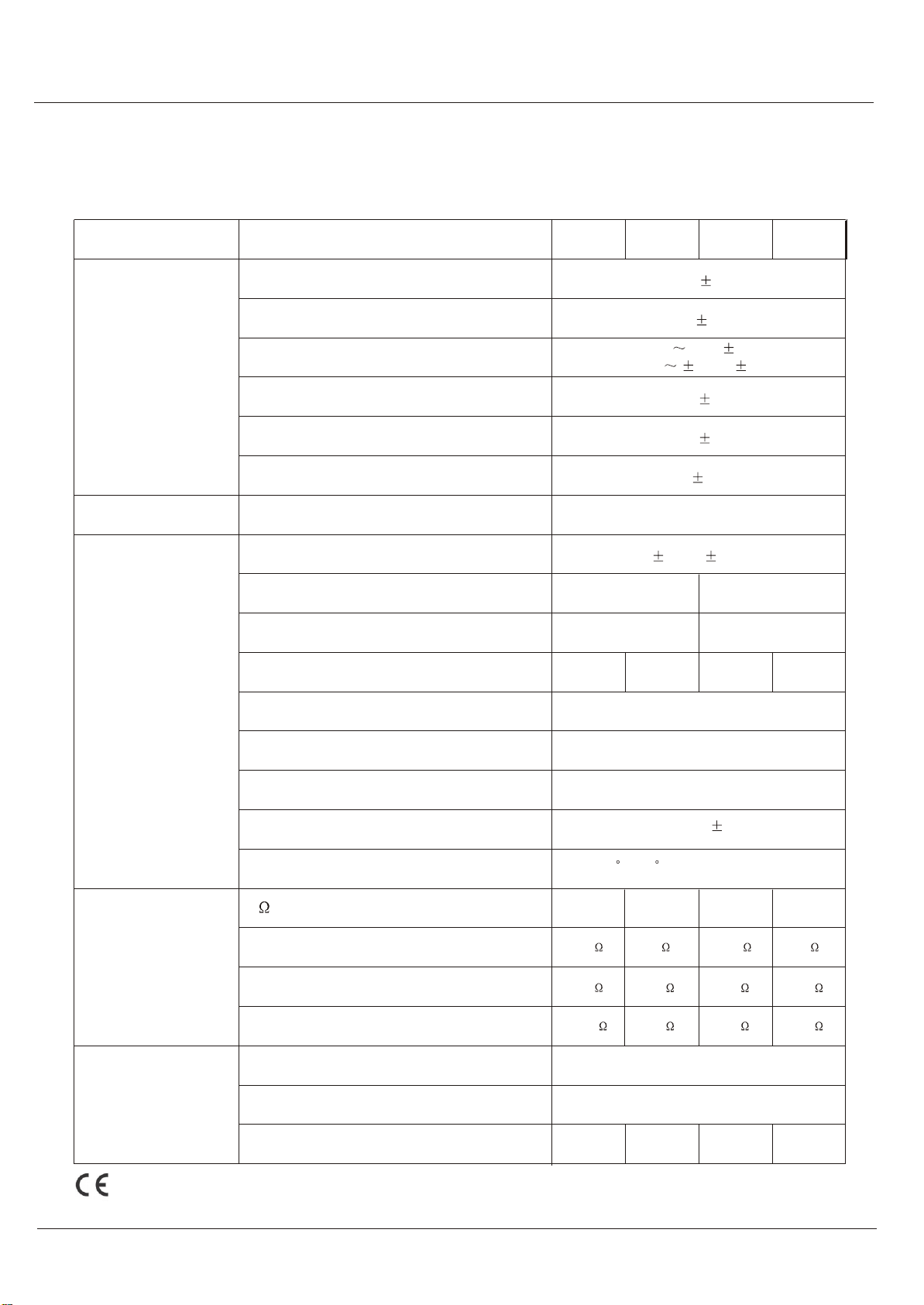
Application
Net Weight
Dimensions (Width/Height/Depth)
Cooling
100V
70V
25V
Operating Temperature/Humidity at
non-condensing
DC Output Offset
Power Band Width at 1kHz from speaker out
tap
Phantom Power
Total Harmonic Distortion(THD) at 1kHz
rated power
Rated Output Power at THD 0.5%
Crosstalk at all control maximum
Signal to Noise Ratio at rated power output
125Hz,250Hz,500Hz,1kHz,2kHz,4kHz,8kHz
at 1 watt from speaker out tap.100Hz~10kHz
Unbalanced Amp-In
Unbalanced Link-In
Balanced Telephone Paging
Balanced Remote Microphone Station(RCA jack)
Balanced Line Channels
Balanced Microphone Channels
4
Input Sensitivity for
full output at maximum
gain
Frequency Response
Graphic Equalizer
Output Voltage and
Impedance
Construction
Specification
Performance
Necessary modification are made without notification
M-5060/M-5120/M-5240/M-5300
-50dB 3dB
-6dB 3dB
-50dB -6dB 3dB
(-30dB 14dB 3dB)
-21dB 3dB
-17dB 3dB
0dB 3dB
+1.5dB / -3dB
12dB 3dB
8.72 kg 9.76 kg 8.5 kg 8.8 kg
420(W) x 88(H)x 320(D) mm
167 83 42 33
81 41 21 46
10 5 2.6 2
15.5V 22V 31V
Convection Cooled
34.6V
Less than 3mV
80Hz~15kHz with less than 0.5% THD
15VDC
Less than 0.5%
60Watts 120Watts 240Watts 300Watts
-70dB at 1kHz -60dB at 1kHz
Better than 90dB Better than 75dB
M-5060 M-5120 M-5240 M-5300
0 ~40 C at 95%humidity
This manual suits for next models
3
Table of contents
Other TKOKO Amplifier manuals


