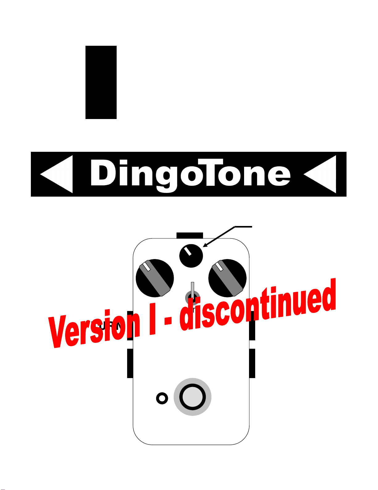
TLM DingoTone User manual
rue
-
bypass
oop
ixer
T
L
M
Input
Signal
Level
Loop
Signal
Level
Power jack
(center negative)
Send level
Send
phase
IN
SENDRETURN
OUT

www.DingoTone.com
Copyright © 2009
PLUG IT IN AND PLAY!
Input Signal
Level
Loop Signal
Level
Send level
Send
phase
INININ
OUT OUT OUT
Connect the TLM as shown.
•Plug the instrument into the IN jack
•Plug the SEND jack of the TLM into the input of the first pedal in the loop
•Plug the output of the last pedal in the loop into the RETURN jack
•Plug the OUT jack of the TLM into the next pedal along or into the amplifier
•Set all controls to “12 o’clock” initially – this will mix equal parts of the input signal with the
loop signal.
•Power the TLM with a battery or an external supply (see later in the instructions for
acceptable supply types), and then turn on the amp.
•For all loop (no input signal), set the Input level to minimum and adjust the Loop level to
taste.
•To blend the input and loop signals, set the Loop level and Input level controls to taste.
www.DingoTone.com
Copyright © 2009
Send level adjustment
•It is important to set the Send level properly – setting it too high can over-drive the loop,
setting it too low can make the loop noisy.
•A good starting point is with the Send level set to “12 o’clock” – this is approximately unity
gain, or, said another way, the level coming out the SEND jack will be about the same as the
signal coming in the IN jack. This usually works just fine, and you can normally leave the
Send level here without worry.
•If you want to drive the loop harder, one way to set the Send level is to wind the Send level
up a little at a time until you hear the loop distorting, then reduce the Send level a little. Take
care with this though because when your picking strength increases in a live situation the
added level can distort the loop unexpectedly.
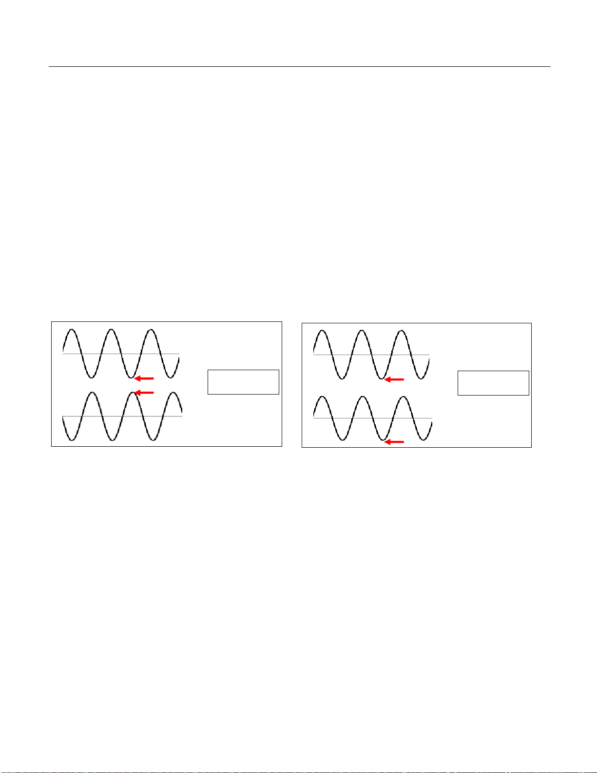
The Send phase
•Some pedals “invert” the phase. What this means is when the voltage at the input of the
pedal is at the maximum, the voltage at the output is a minimum. Like this:
INPUT
OUTPUT
Input and output
“inverse phase”
INPUT
OUTPUT
Input and output
“in phase”
•If the pedals in the loop make the signal coming back from the loop “inverse phase”, then
when the loop signal is mixed with the input signal the sound will go really “thin”. This is very
similar to having one of your stereo speakers wired up the wrong way – it makes the bass
disappear.
•Try the switch – see which position sounds best!
How will you know if the loop is “inverse phase”? Sometimes it is hard to tell, but a good
indicator is if you have all the controls set to “12 o’clock” and it sounds like all the bass has been
removed. If that happens, flick the Send phase switch to the other position – the bass should
come back.
One pedal known to invert the phase is the MXR Phase 90. If you have a Phase 90 in the loop,
try the Send phase switch in each position and pick the one that sounds best.

www.DingoTone.com
Copyright © 2009
TO USE THE TLM AS A CLEAN BOOSTER
Connect the TLM as shown. This works exceptionally well as a booster between single-coil
pickups and the clean channel of a tube amp.
Use this knob as
a “boost” control
Set this knob to minimum
•Leave the SEND and RETURN jacks unconnected.
•Adjust the Input level control to taste – this is the “boost” control.
•To minimize noise, turn the Loop level control (the left one) to minimum.
•The Send phase switch can be left in either position (it has no effect).
•The Send level knob can be left anywhere (it has no effect).
www.DingoTone.com
Copyright © 2009
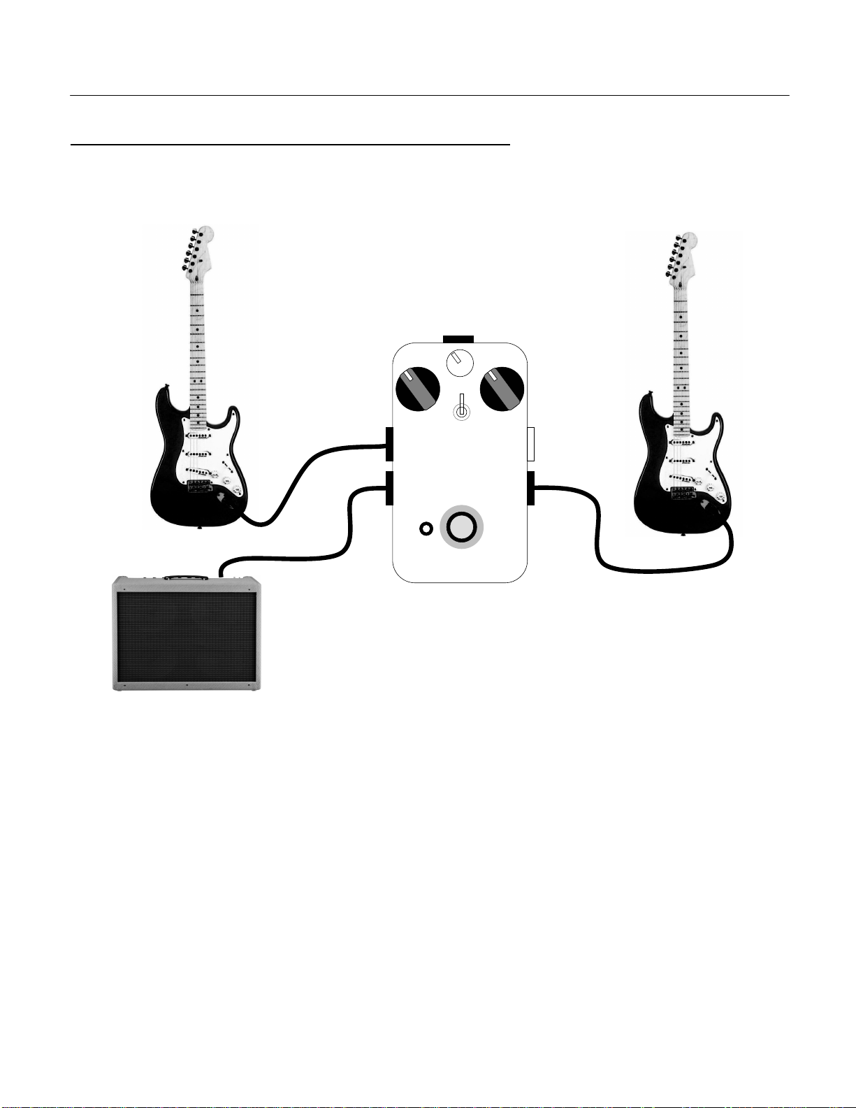
TO USE THE TLM AS A SIMPLE TWO CHANNEL MIXER
Connect the TLM as shown. To connect two guitars to an amp that has a single input, this is the
"right" way to do it. The TLM can also mix two line level signals (stereo) to mono.
Input 1 mixInput 2 mix
Input 1
Input 2
•Leave the SEND jack unconnected.
•The OUT jack has the mix of the two input signals – adjust the levels to taste.
•The Send phase switch can be left in either position (it has no effect).
•The Send level knob can be left anywhere (it has no effect).

www.DingoTone.com
Copyright © 2009
TO USE THE TLM AS A BUFFERED SIGNAL SPLITTER
Connect the TLM as shown. This arrangement splits an instrument signal without making the
instrument drive two loads. This is the “correct” way to split a guitar signal into two amps.
Output 2 level
Output 1 level
Send
phase
(must set to
“up” position)
Output 1
Output 2
Set this knob
to minimum
•Leave the RETURN jack unconnected
•Try the Send phase switch in each position – use the one that sounds best
•To minimize noise, turn the Loop signal level control (the left one) to minimum
www.DingoTone.com
Copyright © 2009
NOTES
•The TLM is designed to work with guitar, however, it can also be used for bass and line-level
signals.
•Assuming the TLM is correctly powered, the TLM is in true-bypass when the LED is off. True-
bypass will work even if power is lost (note that the LED will not indicate the status if power is lost).
•Inserting a lead into the INPUT jack turns power on – note that the INPUT jack is quite stiff.
•Use a 9V battery or DC supply with center negative (see below).
•The TLM may produce hum if the power supply is not regulated. If you experience hum with a
power supply, please change to a regulated supply and power only the TLM from the supply.
•The Send phase switch is “up” (away from the foot switch) for in-phase, “down” (toward the foot
switch) for inverse phase.
POWERING THE TLM
The TLM will happily accept a power supply up to 20VDC. Please note though that the pedal is
designed to be operated from a linear (not switched-mode) regulated supply. If you experience noise
or other power problems using the pedal, please switch to a 9VDC linear regulated supply.
It is important to note that unregulated power supplies can give much greater voltage than the rated
voltage – some 20VDC unregulated supplies can give over 30VDC when lightly loaded.
So the rules of thumb for powering the TLM are:
•If the power supply is regulated, name-plate ratings up to 20VDC are safe.
•If the power supply is unregulated, do not use a supply with a name-plate rating of greater than
about 12VDC without measuring it with a meter first.
SPECIFICATIONS
•Small signal AC input impedance approximately 500kΩ
•Output impedance typically less than 1kΩ
•DC current consumption is approximately 10mA
Exceeding 2
4
VDC
supply
will cause the protection circuitry
to operate and this WILL damage the power supply and/or the pedal.
This is not covered under warranty.
CAUTION
www.DingoTone.com
Copyright © 2009
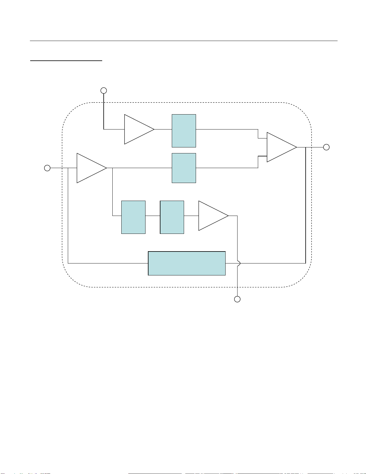
TLM BLOCK DIAGRAM
RETURN
SEND
OUT
IN
Return
buffer
Input
buffer
Send
buffer
Output
buffer
Loop
signal
level
control
Input
signal
level
control
Send
phase
switch
Send
level
control
True bypass circuit
and foot switch

www.DingoTone.com
Copyright © 2009
APPENDIX
MORE ABOUT THE TLM DESIGN
The design for the TLM came about because we had an old phaser that we loved, but it was
“too much”. What we wanted was a true-bypass looper with a volume control – we wanted to
be able to back off the phaser so it wasn’t so “wet”. Kind of like an “effect level” knob on
modern effects.
This was our original concept:

www.DingoTone.com
Copyright © 2009
Managing a loop requires some specific features (e.g. phase control). We have spent
hundreds of hours prototyping, testing, and evolving the design of a pedal to do the job
properly.
What we have ended up with is an extremely versatile pedal. It can be used as a:
•clean booster
•simple two channel mixer
•buffered signal splitter
•and, of course, a “loop-mixer”
We wanted to preserve tone, so we have used high quality 4558 opamps in the TLM. What
this means to you is that your guitar tone is not “sucked”, and if the TLM is ever driven hard
enough to distort, it will give a smooth breakup.
We are very proud of this pedal, and we hope it gives you years of enjoyment!
Table of contents


