TMEIC TMdrive-XL Series User guide

power
generation
solar
inverters
oil & gastestingminingcranes cementmetals
TMdrive®-XL Series Family
Product Application Guide
TM
drive
®
-XL
S
eries Family
Product Application Guide

2
TMdrive-XL Series
TheTMdrive XL series family of variable frequency drives (VFD) provides
the high power levels and speed required to drive large motors that power
rotating machinery used in the Oil & Gas industry. Important VFD features
common to the family include:
• Common architecture, pulse width modulation and control, water
cooling, I/O modules, andTMdrive-Navigator programming software
• Multi-level VFD output for smooth waveform to the motor
• 24-36 pulse diode converter rectifier for low harmonic distortion
• High VFD reliability and availability with MTBFs in excess of 20 years
and MTTR of less than 30 minutes.
• Output frequency range high enough for direct compressor drive
with no gearbox, eliminating costly lube oil systems in addition to the
gearbox, resulting in increased system efficiency.
• Up to 7.2 kV supply to the motor with no output transformer required
• Ability to operate drive banks in parallel for higher power levels up to
120 MVA
2
15/30 MVA
Power Module
Single Phase
Inverter using GCTs
15 MVA
8 MVA 20 MVA 30 MVA
Diode Rectifier,
36-pulse, one of
six modules.
Inverter modules,
two modules make
a five-level single
phase inverter
Induction or
Synchronous
Motor
Power supply,
three-phase
50/60 Hz
Externally mounted
input transformer
and zero impact on
building HVAC cost
Field windings
for Synchronous
Motor
for low harmonic
power system impact
Up to 64 kV
20 MVA VFD
Power Module
Single Phase
Inverter using IEGTs
8 MVA VFD
Power Module
Single Phase
Inverter using IGBTs
5.5 kA, 4.5 kV
6 kA, 6 kV
0.9 kA, 4.5 kV
XL Architecture using Diode Converter and
five-level Pulse Width Modulated Inverter
Three different inverter modules for
this architecture, three per VFD:
IGBT
IEGT
GCT
XLdrive Series Family Application Guide.indd 2 10/3/2011 3:15:44 PM

3
Variable
Frequency
Drive
Reactor
Reactor AC Machine
AC Machine
AC Machine
Variable
Frequency
Drives
Variable
Frequency
Drives
3
XLDriveFamilyPowerExpansion
Higher Power Levels. The XL VFDs can be run in
parallel to produce higher power levels than single
banks. Two, three, or four banks can be combined
to obtain the desired power. The example below
shows how an XL VFD can be expanded to four
banks for a power of 120 MVA (156,000 hp). The
table shows the maximum power levels available
from the VFD family.
The multi-bank VFDs provide drive and control
redundancy for improved reliability.
• Synchronous or Induction motor can control
rotating machinery directly for low and high
speed applications.
• A redundant control cabinet significantly
enhances reliability.
• Synchronous motor can control rotating
machinery directly for low and high speed
applications; paralleling reactor feeds the motor
• A redundant control cabinet significantly
enhances reliability.
• Synchronous motor can control rotating
machinery directly for low and high speed
applications ; paralleling reactor feeds the motor
• One bank can be redundant to other three banks
for increased reliability.
One-Bank TMdrive-XL – Power level up to 30 MVA
Two-Bank TMdrive-XL – Power level up to 60 MVA
Four-BankTMdrive-XL – Power level up to 120 MVA
XL Drive Power Levels, Single Bank Multiple Banks, Max
TMdrive-XL85 30 MVA (39,000 hp) 120 MVA (156,000 hp)
TMdrive-XL75 20 MVA (26,000 hp) 80 MVA (104,000 hp)
TMdrive-XL80 15 MVA (19,500 hp) 30 MVA (39,000 hp)
TMdrive-XL55 8 MVA (10,400 hp) 16 MVA (20,800 hp)
XLdrive Series Family Application Guide.indd 3 10/3/2011 3:15:55 PM

4
TMdrive-XL Series
Power Rating: 8 MVA, expandable to 16 MVA
Output Voltage: 6.6 kV
Output Frequency: Rated 50-60 Hz, 50 to 250 Hertz option
Dimensions: Width 6.5 m
Height: 2.5 m
Motor type: Synchronous
or Induction
Power Input/Output
Converter
• AC-fed 36-pulse diode rectifier using externally
mounted phase shifted transformer; no harmonic filter
required to meet IEEE 519 guidelines
• DC bus voltage: 3 x 5,000 Vdc
• Power factor greater than 95% in speed control range
Inverter
• Five-level inverter for motor friendly wave form
• Uses 8 IGBT devices for each of three phases
• 6 kV output to motor – no output transformer required
• Inverter power modules water cooled
• Conservative design for expected 20 year MTBF
Input Voltage
Any utility voltage using
separate transformer input
50/60 Hz ±2%
Output Voltage 6,600 Vac
Output Current 700 A rms
Output Frequency 50-60 Hz, for over 75 Hz,
consult TMEIC
Output Chopping 600 Hz (max)
Efficiency 98.6%
Cable Entry Bottom or top
Clean Motor Output Wave
As a result of the five-
level PWM control, the
output current waveform
is close to a sine wave.
Harmonic currents in
the motor windings are
minimized so the heat
loss is negligible and
there is very little shaft
torque ripple. Illustrated
waveform is from the
similar TMdrive XL85 test.
Line-to-Line Voltage at 100% Speed
U-phase Current at 100% Speed
Protective Functions Include:
• Inverter overcurrent
• Inverter overvoltage
• Low system voltage
• Motor ground fault
• Motor overload
• Cooling fan abnormal
• Over-temperature
• CPU error
• Water cooling alarm
• Exciter fault
• DC voltage drop
• Motor inverse rotation
• Stall detection
• Ground detection
Frequency Control
• Volt/Hertz Control – standard
• Sensorless vector control - optional
Output Voltage Modulation
The output switching modulation strategy is dynamically
adjusted based on three speed zones to minimize motor
torque pulsation.
Drive Inputs
• LAN Interface Options: Profibus-DP, DeviceNet,
Modbus RTU, TOSLINE
• Input/Output: 6 Analog I/O, 8 Digital I/O
Power Circuits
Motor Control
Insulated Gate Bipolar
Transistor (IGBT). Rated
4,500 Volts, 900 Amps.
TMdrive-XL55 – 8 MVA Frame
XLdrive Series Family Application Guide.indd 4 10/3/2011 3:15:56 PM

5
Power Rating: 20 MVA, expandable to 80 MVA
Output Voltage: 6 kV
Output Frequency: Rated 50-60 Hz, 50 to 250 Hertz
Power Input/Output
Converter
• AC-fed 36-pulse diode rectifier using externally
mounted phase shifted transformer; no harmonic filter
required to meet IEEE 519 guidelines
• DC bus voltage: 3 x 4,540 Vdc
• Power factor greater than 95% in speed control range
Inverter
• Five-level inverter for motor friendly wave form
• Uses 8 IEGT devices for each of three phases
• 6 kV output to motor – no output transformer required
• Inverter power modules water cooled
• Conservative design for expected 20 year MTBF
Input Voltage
Any utility voltage using
separate transformer input
50/60 Hz ±2%
Output Voltage 5,820 Vac
Output Current 1925 A rms
Output Frequency 50-60 Hz
Output Chopping 600 Hz (max)
Efficiency 98%
Cable Entry Top or bottom
Clean Motor Output Wave
As a result of the five-
level PWM control, the
output current waveform
is close to a sine wave.
Harmonic currents in
the motor windings are
minimized so the heat
loss is negligible and
there is very little torque
ripple on the output shaft.
Line-to-Line Voltage at 100% Speed
U-phase Current at 100% Speed
Protective Functions Include:
• Inverter overcurrent
• Inverter overvoltage
• Low system voltage
• Motor ground fault
• Motor overload
• Cooling fan abnormal
• Over-temperature
• CPU error
• Water cooling alarm
• Exciter fault
• DC voltage drop
• Motor inverse rotation
• Stall detection
• Ground detection
Frequency Control
• Volt/Hertz Control – standard
• Sensorless vector control – optional
• Power factor control for synchronous motors
Output Voltage Modulation
The output switching modulation strategy is dynamically
adjusted based on three speed zones to minimize motor
torque pulsation.
Drive Inputs
• LAN Interface Options: Profibus-DP, DeviceNet,
Modbus RTU, ISBus,TOSLINE
• Input/Output: 6 Analog I/O, 8 Digital I/O
Power Circuits
Motor Control
Injection Enhanced Insulated
Gate Transistor (IEGT). Rated
4,500 Volts, 2,100 Amps
TMdrive-XL75 – 20 MVA Frame
Dimensions: Width 9.4 m
Height: 2.7 m
Motor type: Synchronous or Induction
XLdrive Series Family Application Guide.indd 5 10/3/2011 3:16:06 PM

6
TMdrive-XL Series
Power Rating: 30 MVA, expandable to 120 MVA
Output Voltage: 7.2 kV
Output Frequency: Rated 50-60 Hz, 50 to 200 Hertz
Power Input/Output
Converter
• AC-fed 36-pulse diode rectifier using externally
mounted phase shifted transformer; no harmonic filter
required to meet IEEE 519 guidelines
• DC bus voltage: 3 x 5,450 Vdc
• Power factor greater than 95% in speed control range
Inverter
• Five-level inverter for motor friendly wave form
• Uses 8 GCT devices for each of three phases
• 7.2 kV output to motor – no output transformer
required
• Inverter power modules water cooled
• Conservative design for expected 20 year MTBF
Input Voltage
Any utility voltage using
separate transformer input
50/60 Hz ±10%
Output Voltage 7,200 Vac
Output Current 2400 A rms
Output Frequency 50-60 Hz
Output Chopping 600 Hz (max)
Efficiency 98%
Cable Entry Top or bottom
Clean Motor Output Wave
As a result of the five-
level PWM control, the
output current waveform
is close to a sine wave.
Harmonic currents in
the motor windings are
minimized so the heat
loss is negligible and
there is very little torque
ripple on the output shaft.
Line-to-Line Voltage at 100% Speed
U-phase Current at 100% Speed
Protective Functions Include:
• Inverter overcurrent
• Inverter overvoltage
• Low system voltage
• Motor ground fault
• Motor overload
• Cooling fan abnormal
• Over-temperature
• CPU error
• Water cooling alarm
• Exciter fault
• DC voltage drop
• Motor inverse rotation
• Stall detection
• Ground detection
Frequency Control
• Volt/Hertz Control – standard
• Sensorless vector control – optional
• Power factor control for synchronous motors
Output Voltage Modulation
The output switching modulation strategy is dynamically
adjusted based on three speed zones to minimize motor
torque pulsation.
Drive Inputs
• LAN Interface Options: Profibus-DP, DeviceNet,
Modbus RTU, TOSLINE
• Input/Output: 6 Analog I/O, 8 Digital I/O
Power Circuits
Motor Control
Gate Commutated Thyristor
(GCT) with driver board.
Rated 6,000 Volts, 6,000
Amps - the world’s largest
switching device
TMdrive-XL85 – 30 MVA Frame
Dimensions: Width 8.1 m
Height: 2.6 m
Motor type: Synchronous or Induction
d
r
i
v
e
-
X
L
8
5
–
3
0
M
V
A
F
r
a
m
e
XLdrive Series Family Application Guide.indd 6 10/3/2011 3:16:12 PM

7
Power Input/Output
Converter
• AC-fed 12- or 24-pulse diode rectifier using externally
mounted phase shifted transformer; no harmonic filter
required to meet IEEE 519 guidelines
• DC bus voltage: 3 x 5,700 Vdc
• Power factor greater than 95% in speed control range
Inverter
• Three-level inverter for motor friendly wave form
• Uses 4 GCT devices for each of three phases
• 3.8 kV output to motor – no output transformer
required
• Inverter power modules water cooled
• Conservative design for expected 20 year MTBF
Input Voltage
Any utility voltage using
separate transformer input
50/60 Hz ±10%
Output Voltage 3,800 Vac
Output Current 2400 A rms
Output Frequency 50-60 Hz
Output Chopping 600 Hz (max)
Drive Efficiency 98%
Cable Entry Top or bottom access
A Clean Output Wave
As a result of the three-level PWM control, the output
current waveform is close to a sine wave. Harmonic
currents in the motor are minimized so the heat loss is
negligible and there is very little torque ripple on the
output shaft.
Protective Functions Include
• Inverter overcurrent
• Inverter overvoltage
• Low system voltage
• Motor ground fault
• Motor overload
• Cooling fan abnormal
• Over-temperature
• CPU error
• Water cooling alarm
• Exciter fault
• DC voltage drop
• Motor inverse rotation
• Stall detection
• Ground detection
Frequency Control
• Volt/Hertz Control
• Vector control
• Power factor control for synchronous motors
Output Voltage Modulation
The output switching modulation strategy is dynamically
adjusted based on three speed zones to minimize motor
torque pulsation.
Drive Inputs
• LAN Interface Options: Profibus-DP, DeviceNet,
Modbus RTU,TOSLINE S-20
• Input/Output: 6 Analog I/O, 8 Digital I/O
Power Circuits
Motor Control
Gate Commutated Thyristor
(GCT) with driver board.
Rated 6,000 Volts, 6,000
Amps - the world’s largest
switching device.
TMdrive-XL80 – 15 MVA Frame
Power Rating: 15 MVA, expandable to 30 MVA
Output Voltage: 3.8 kV
Output Frequency: Rated 50-60 Hz, 50 to 200 Hertz
option with derate above 100 Hz
Dimensions: Width 4.8 m; Height: 2.7 m
Motor type: Synchronous or Induction
XLdrive Series Family Application Guide.indd 7 10/3/2011 3:16:15 PM

TMEIC Corporation
Office: 1325 Electric Road, Suite 200
Roanoke, VA, United States 24018
Mailing: 2060 Cook Drive
Salem, VA, United States 24153
Tel.: +1-540-283-2000; Fax: +1-540-283-2001
TMEIC Houston Branch
2901 Wilcrest Dr., Suite 110
Houston,Texas, 77042, USA
Tel: +1-713-784-2163; Fax: +1-712-784-2842
TOSHIBA MITSUBISHI-ELECTRIC INDUSTRIAL SYSTEMS
CORPORATION
Mita 43, MT Bldg.
13-16 Mita 3 chome, Minato-ku
Tokyo, Japan, 108-0073
Tel.: +81-3-5444-3828; Fax: +81-3-5444-3820
Web: www.tmeic.co.jp
TOSHIBA MITSUBISHI-ELECTRIC INDUSTRIAL
SYSTEMS
(Beijing) CORPORATION
21/F., Building B, In.do Mansion
48 Zhichunlu A, Haidian District
Beijing 100098, PRC
Tel.: +86 10 5873-2277; Fax: +86 10 5873-2208
TMEIC Europe Limited
6-9 The Square, Stockley Park
Uxbridge, United Kingdom, UB11 1FW
Tel.: +44 870 950 7220; Fax: +44 870 950 7221
TMEIC Industrial Systems India Private Limited
901/D, Filix, L.B.S. RoadOpp Asian Paints, Bhandup
West Mumbai, Maharashtra, India, 400 078
Tel.: +91-40-4434-0000; Fax: +91-40-4434-0034
Email: [email protected]
Web: www.tmeic.com/india
TMdrive is a registered trademark ofTOSHIBA MITSUBISHI-ELECTRIC INDUSTRIAL
SYSTEMS CORPORATION.
All other products mentioned are registered trademarks and/or trademarks of their
respective companies. All specifications in this document are subject to change
without notice.
All specifications in this document are subject to change without notice. The above
brochure is provided free of charge and without obligation to the reader or to
TMEIC.
TMEIC Corporation does not accept, nor imply, the acceptance of any liability
with regard to the use of the information provided.TMEIC Corporation provides
the information included herein as is and without warranty of any kind, express
or implied, including but not limited to any implied statutory warranty of
merchantability or fitness for particular purposes.The information is provided
solely as a general reference to the potential benefits that may be attributable to
the technology discussed. Individual results may vary. Independent analysis and
testing of each application is required to determine the results and benefits to be
achieved from the technology discussed. If you have any questions regarding your
project requirements, please contact TMEIC Corporation at 540-283-2301.
© 2011 TMEIC Corporation. All Rights Reserved. P- 114 5-A
Over 300 Service
Engineers world wide
Life Cycle Support from Commissioning to Post Sales Service
TMEIC offers comprehensive Customer Support, from pre-planning, through design,
commissioning and post sale service.
Over 70 Service Engineers
across North America
Customer Service Call Center
• Open 24x7x365
• Staffed by trained service engineers
• Supported by factory design engineers
Remote Drive and System Diagnostics
• Global Connectivity
• Quick Resolution
Motor and Generator Service
• EASA Service Centers supportTMEIC Motors
Commissioning and CustomerTraining
• Experienced commissioningTeam
• Comprehensive factory acceptance test
• Training of the entire team on the system at the
factory
• Customized training courses for allTMEIC
automation and control systems, drives , motors,
generators and otherTMEIC products
XLdrive Series Family Application Guide.indd 8 10/3/2011 3:16:19 PM
This manual suits for next models
4
Table of contents
Popular DC Drive manuals by other brands

GFA ELEKTROMATEN
GFA ELEKTROMATEN ST 16.24-40.00 installation instructions
Lenze
Lenze Tmd operating instructions
Omron
Omron SYSDRIVE 3G3JV quick start guide

Inovance
Inovance MD520 Series Safety function Guide
LiftEquip
LiftEquip MFC-16 Series Installation instruction
Danfoss
Danfoss VLT DriveMotor FCM 106 Design guide
Danfoss
Danfoss VLT 2800 manual

Siemens
Siemens Sinamics SM150 6SL3845-2NN41-8AD0 Operating and installation instructions
WEG
WEG CFW-11 Series user manual

SEW-Eurodrive
SEW-Eurodrive Movidrive MDX61B operating instructions
Hubbell
Hubbell Universal Cable Reel-Direct Drive UE28 Installation and maintenance instructions
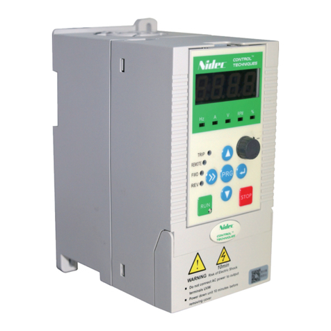
Nidec
Nidec NE200 Series quick start guide
