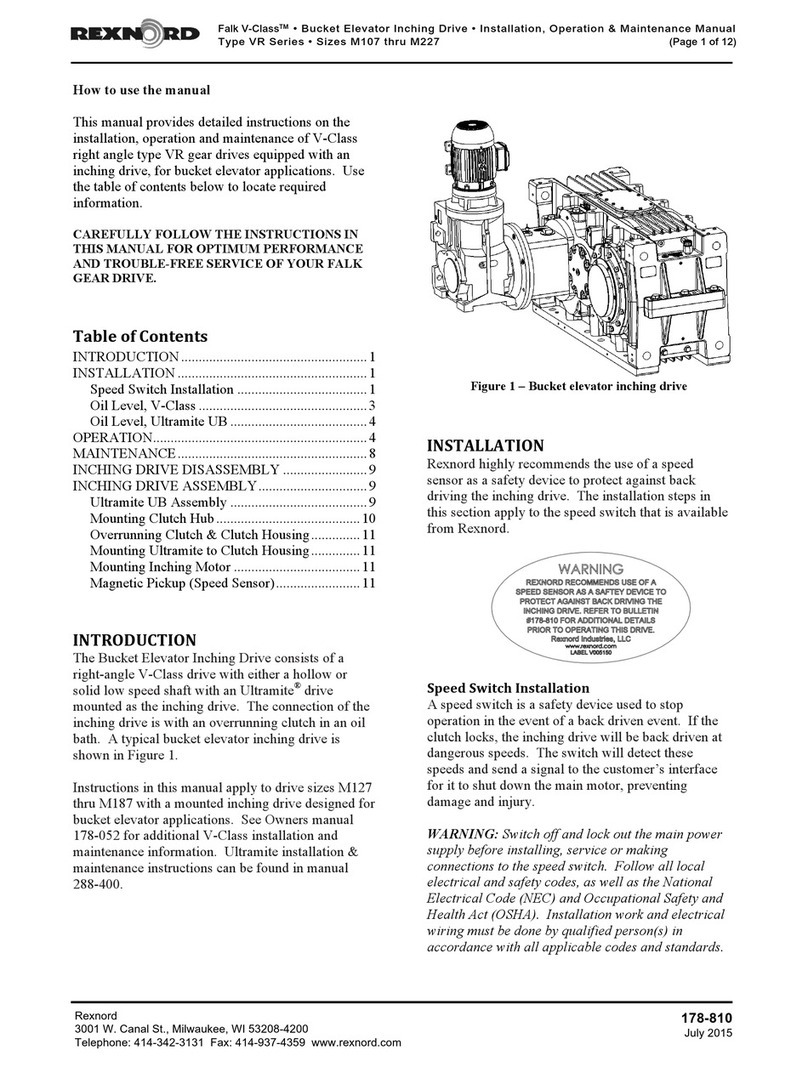
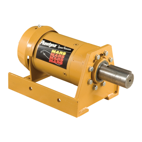
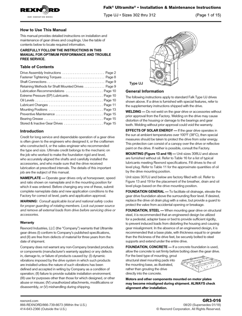
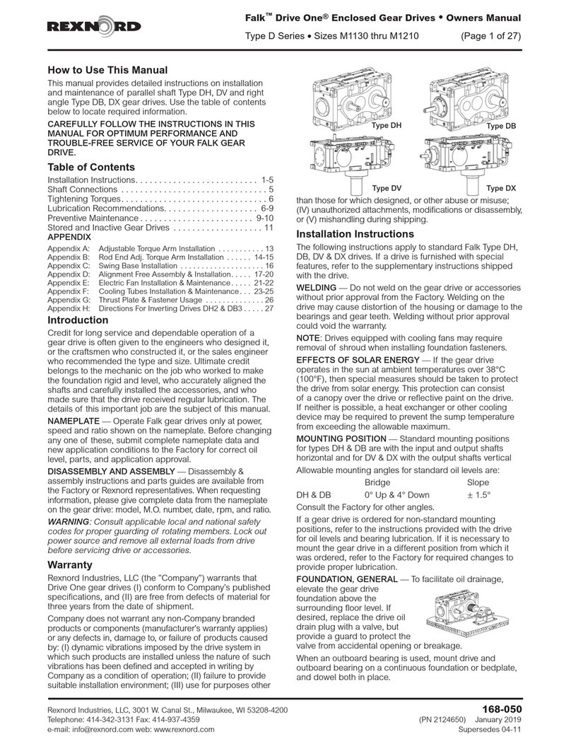
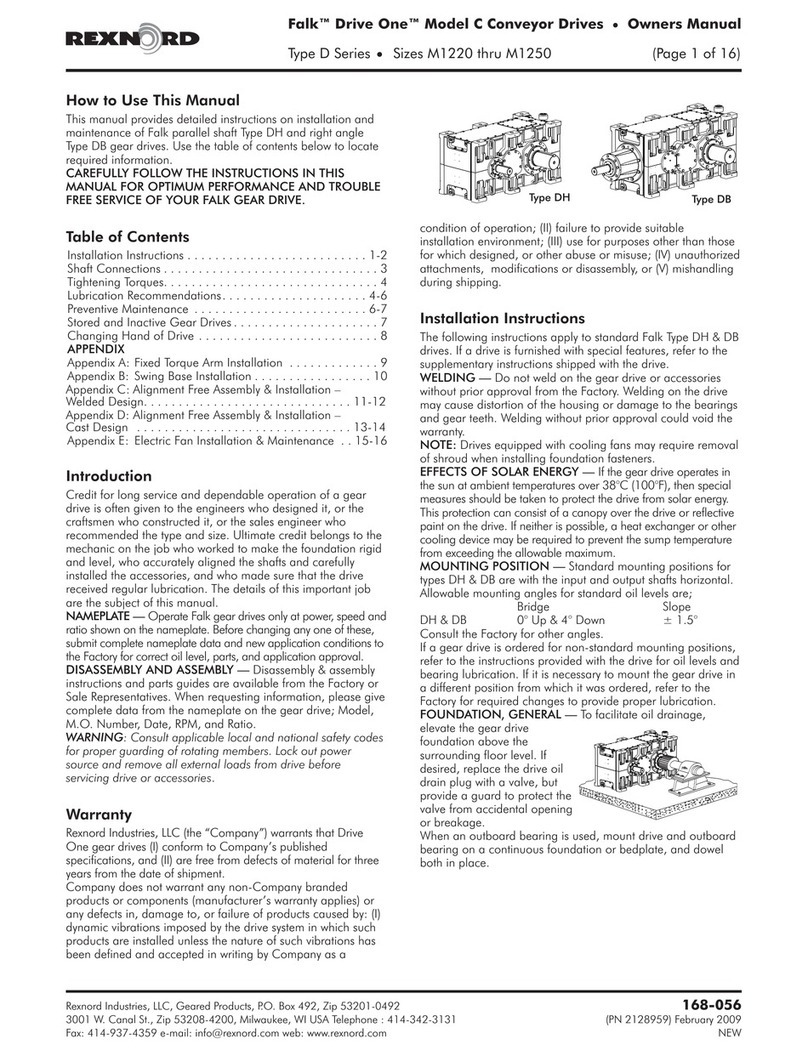
Rexnord Falk CT Series Installation guide

Falk®CT-Series Gear Drives • Operation and Maintenance
Sizes 2160 thru 2400 (Page 1 of 7)
Rexnord GR3-014
3001 W. Canal St., Milwaukee, WI 53208-4200 January 2017
Telephone: 414-937-4359 Fax: 414-937-4359 www.rexnord.com NEW
How to Use this Manual
This manual provides detailed instructions on installation
and maintenance of Falk CT-Series gear drive. Use the
table of contents below to locate required information.
CAREFULLY FOLLOW THE INSTRUCTIONS IN THIS
MANUAL FOR OPTIMUM PERFORMANCE AND
TROUBLE-FREE SERVICE OF YOUR FALK GEAR DRIVE.
TABLE OF CONTENTS
1. Introduction .....................................................................1
2. General Notes and Safety Instructions............................1
3. Transport and Storage.....................................................2
4. Installation .......................................................................3
5. Shaft Connections ...........................................................5
6. Lubrication.......................................................................5
7. Preparation For Test Run .................................................5
8. Maintenance....................................................................6
1. INTRODUCTION
Credit for long service and dependable operation of a
gear drive is often given to the engineers who designed it,
or the craftsmen who constructed it, or the sales engineer
who recommended the type and size. Ultimate credit
belongs to the mechanic on the job who worked to make
the foundation rigid and level, who accurately aligned the
shafts and carefully installed the accessories, and who
made sure that the drive received regular lubrication. The
details of this important job are the subject of this manual.
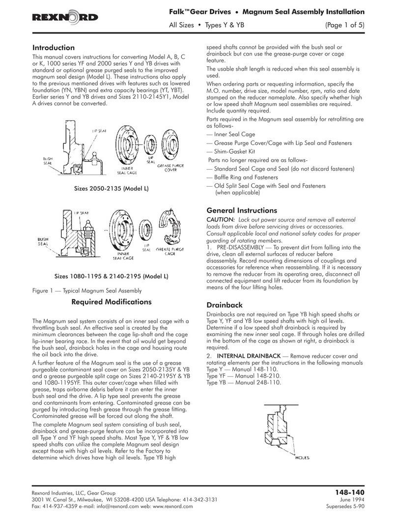
NAMEPLATE — Operate Falk gear drives only at power,
speed and ratio shown on the nameplate. Before changing
any one of these, submit complete nameplate data and
new application conditions to Factory for correct oil level,
parts, and application approval.
LUBRICATION — Lubrication of gears and bearings is
entirely self-contained by splash. In general oil grade to be
used is ISO-VG 320. Oil thrower on input shaft produces
positive splash which in turn, ensures continuous
circulation of oil to top bearings through channels.
WARNING: Consult applicable local and national safety
codes for proper guarding of rotating members. Lock out
power source and remove all external loads from drive
before servicing drive or accessories.
WARRANTY — Rexnord Industries, LLC (the ”Company”)
warrants that Falk V-Class™gear drives (I) conform to
Company’s published specifications, and (II) are free from
defects of material for two years from the date of shipment.
Company does not warrant any non-Company branded
products or components (manufacturer’s warranty applies)
or any defects in damage to, or failure of products caused
by: (I) dynamic vibrations imposed by the drive system in
which such products are installed unless the nature of such
vibrations has been defined and accepted in writing by
Company as a condition of operation; (II) failure to provide
suitable installation environment; (III) use for purposes other
than those for which designed, or other abuse or misuse;
(IV) unauthorized attachments, modifications or disassembly,
or (V) mishandling during shipping.
QUALIFIED PERSONNEL — The product or system
to which these instructions relate may be handled only
by persons qualified for the work concerned and in
accordance with the instructions relating to the work
concerned, particularly the safety and warning notes
contained in those instructions. Qualified personnel must
be specially trained and have the experience necessary to
recognize risks associated with these products or systems
and to avoid possible hazards.
2. GENERAL NOTES AND SAFETY
INSTRUCTIONS
The proper working of a gear unit not only depends on
the good design, the use of good material and good
workmanship but also on careful installation, proper
lubrication and proper working conditions. Hence, it is
of utmost importance to see that the installation of the
gear box is one according to the instructions given in this
manual to ensure proper working of the gear box and to
ensure a long and trouble free service.
This manual should be kept with the person in-charge
who handles the installation & operation. They should
thoroughly study and understand the instructions
given in this manual. Precisely following of this manual
will give trouble free working of the Gear unit. In the
interest of future development, we reserve the right to
introduce modifications to the individual subassemblies &
accessories, which, while retaining the essential features,
can be regarded as desirable to increase their efficiency,
reliability and safety.
2.1 INSTRUCTIONS FOR LONG STORAGE OF GEAR
UNITS
Following instructions for the long time storage of the
gear units is of extreme importance as violation of
which can lead to the premature failure.
Long time storage of a gear unit can be due to:
2.1.1 Unit is not in action, however, installed in the place
2.1.2 Unit is kept in store and waiting for its use.
OR
2.1.3 The unit is installed but not in action:
When the gear unit is installed in the system
but is out of action, a quantity of oil must be
added to exceed maximum level by 30 mm to
50 mm. Special attentions should be given to
the condition of the oil. Old oil, which may form
a deposit or be acidic, should be removed.
The gears should be turned slowly by hand at
intervals, in order to ensure the oil is distributed
over all parts in contact. Wherever grease nipples
are provided, add grease through grease nipples.
2.1.4 The unit is to be stored for a long time:
When the unit is to be stored for a long time, it
should be run for 5 minutes after filling with rust
protective oil. The level of the oil should be about
30 mm to 50 mm higher than the normal oil level.
All the parts having been thoroughly coated with
oil, the protective fluid can be drained and kept
for other similar operations.
The inspection covers and the drain plugs should
be completely sealed. On starting up the speed
reducer, no special precaution need be taken
Falk®CT-Series Gear Drives • Operation and Maintenance
(Page 2 of 7) Sizes 2160 thru 2400
GR3-014 Rexnord
January 2017 3001 W. Canal St., Milwaukee, WI 53208-4200 USA
NEW Telephone: 414-937-4359 Fax: 414-937-4359 www.rexnord.com
other than filling the oil bath according to the
recommended quantity and quality of lubricating
oil. To prevent corrosion during storage, Silica Gel
bags should be kept in the vicinity of the gear
unit. NOT INSIDE GEAR CASE. Silica Gel should
be periodically checked for moisture absorption
and be changed from time to time.
2.2 GENERAL REMARKS
The inner parts of new units leaving our Works
are sprayed with a rust protective oil which keeps
them free from rust for 6 months, provided they are
sheltered from atmospheric elements, preferably in a
closed ventilated place. When putting into operation,
proceed as per instructions of this manual. When
storing the units leave them in the cases through which
they have been forwarded. Do not put them near
vibrating machines, such as reciprocating engines,
compressors and pumps in order to avoid wear of
bearings by vibration. For a gear box that has to be
stored for more than 6 months the gear should be
treated as per procedure laid down in 2.1.4 i.e. to run
the gear with rust protective for 5 minutes.
2.3 OBLIGATIONS OF THE USER
The operator must ensure that everyone carrying out
work on the gear unit has read and understood these
instructions and is adhering to them in every point in
order to:
Avoid injury or damage,
Ensure the safety and reliability of the unit,
Avoid disruptions and environmental damage through
incorrect use
During transport, assembly, installation, dismantling,
operation and maintenance of the unit, the relevant
safety and environmental regulations must be
complied with at all times.
The gear unit may only be operated, maintained and/or
repaired by persons qualified for the work concerned
(see “Qualified personnel” on page 1 of this manual).
The outside of the gear unit must not be cleaned with
high-pressure cleaning equipment
A potential equalization in accordance with the
applying regulations and directives must be carried
out! If no threaded holes for earth connection are
available on the gear unit, other appropriate measures
must be taken. This work must always be done by
specialist electricians.
Removed safety equipment must be re-installed prior
to starting up.
Notices attached to the gear unit, e.g. rating plate,
direction arrows etc., must always be observed. They
must be kept free from dirt and paint at all times.
Missing plates must be replaced.
Screws which have been damaged during assembly
or disassembly work must be replaced with new ones
of the same strength class and type.
2.4 ENVIRONMENTAL PROTECTION
Dispose of any packing material in accordance with
regulations or separate it for recycling.
When changing oil, the used oil must be collected in
suitable containers. Any pools of oil which may have
collected should be removed at once with an oil-
binding agent.
Preservative agents should be stored separately from
used oil.
Used oil, preservative agents, oil-binding agents and
oil-soaked cloths must be disposed of in accordance
with environmental legislation.
Disposal of the gear unit after its useful life:
Drain all the operating oil, preservative agent and/
or cooling agent from the gear unit and dispose of in
accordance with regulations.
Depending on national regulations, gear-unit
components and/or add-on parts may have to be
disposed of or sent for recycling separately.
3. TRANSPORT AND STORAGE
The gear unit is delivered in the fully assembled condition.
Additional items are delivered separately packaged, if
applicable Different forms of packaging may be used,
depending on the size of the unit and method of transport.
Transport of the complete gear unit should be undertaken
by using wire ropes / cable strips of required strength.
While lifting the complete gear unit, please do not use
the shaft and lugs provided on the casing. Use the
4 lifting lugs provided on top part of the gear cases.
(See Fig. 1a. & 1b).
Lift the gear unit which is fitted with lubrication piping
carefully in such a way as to avoid any damage to the
piping system.
3.1 STORING THE GEAR UNIT
The gear unit must be stored in a sheltered place in
the position of the original packaging or in the position
of use, placed on a vibration-free, dry base, and
covered over.
Provision for special environmental conditions during
transport (e.g. transport by ship) and storage (climate,
termites, etc.) must be contractually agreed.
Fig. 1a. Incorrect way of
lifting gearbox
Fig. 1b. Correct way of
lifting gearbox

Falk®CT-Series Gear Drives • Operation and Maintenance
Sizes 2160 thru 2400 (Page 3 of 7)
Rexnord GR3-014
3001 W. Canal St., Milwaukee, WI 53208-4200 January 2017
Telephone: 414-937-4359 Fax: 414-937-4359 www.rexnord.com NEW
3.2 DELIVERY CONDITIONS
All gear units are manufactured with highest quality
control and keeping the exact specifications in mind.
The gears are carefully inspected at various stages
and run on the test bed. After all the quality control
tests are made, the gear units sealed and certified for
dispatch. The seal on the gear should not be removed
without our prior consent. If the same is removed
without our consent, will automatically relieve us from
our guarantee.
Gear units are packed in wooden cases having
suitable battens to facilitate handling. Casings are
marked with the symbol showing the position of gear
unit, inside the casing.
The gear units are supplied without filling up of
oil. Recommended oil has to be filled in before
commissioning the unit.
Wherever grease lubrication points are provided, the
grease filling is done at the manufacturing facility.
Grease seals during oil change intervals. Depending
on the degree of contamination, it may be necessary
to purge contaminated grease from seals more often
(at least every 3 to 6 months). Purge grease from seals
by first cleaning grease fitting and then slowly pump
fresh grease, WITH A HAND GREASE GUN, through
the seal cavity until fresh grease flows out along the
shaft. Wipe off purged grease. Cooling accessories
can be removed to access grease purge without
removing shaft connection on motor.
3.3 PRESERVATION
3.3.1 General — All bright parts such as shaft ends
are given a coat of anti-rust compound ‘Suprabha
make VCI 602 Rustojel’. Anti-rust compound is
easily removable by applying mineral turpentine
oil or nitro-thinners or suitable solvents. Please do
not use files or sand papers for removal of anti-
rust coating.
If the gear unit is required to be stored for a long
time before putting into operation, then please
follow the instructions given earlier (see chapter
3.3.4 & 3.3.5) in this manual to prevent premature
damage to the gear unit.
Interior preservation: VCI-412 or equivalent (see
chap. 3.3.2)
Exterior preservation: VCI-602 or equivalent (see
chap. 3.3.2)
3.3.2 Interior preservation — The internal rotating
elements of all gear drives are sprayed with
Suprabha’s VCI-412 before they leave the
plant. This internal spray coating is good for
approximately 6 months indoor storage. So
VCI-412 is used inside gearbox. The VCI-412 is
to be sprayed by opening inspection window.
Rotate input shaft in one direction while spraying
VCI-412 to apply on all internals rotating parts
& all accessible areas. Also rotate input shaft in
reverse direction to apply VCI-412 on all internals
& bearings. The anticorrosion oil VCI-412 will fully
dissolve during putting into operation provided
the operating oil in accordance with the lubricants
chart (see chapter 6) is used.
3.3.3 Exterior preservation — The exterior
preservation of blank parts is carried out
independently from the interior preservation.
Outside surfaces of gearbox are sprayed with
Suprabha’s VCI-602. This VCI-602 is a ready-to-
use petroleum jelly. Upon application, a tenacious
film is created on surface. The vapours released
By VCI (Vapour Corrosion Inhibition) create a
protective vapour barrier that keeps corrosion
promoting agents like moisture and oxygen
away. This outside spray coating is good for
approximately 18-24 months indoor and 10-12
months outdoor.
3.3.4 Period of corrosion protection — The gear must
be stored inside a room spanned by a roof. The
ambient temperature in stock must not exceed
50°C. Furthermore, the storage conditions must
be such as to prevent foreign bodies (water, dust)
entering the gear.
If the gear is stored for a period exceeding one
year upon supply ex-works, interior and exterior
preservation must be checked every 5-6 months
and renewed. If the gear is stored, however, in an
outdoor area under cover or a tropical country,
preservation must be checked every 6 months
and renewed.
For renewal of preservation, the instructions of
the chapter 3.3.5 must be adhered to.
3.3.5 Renewal of gear unit preservation — A renewal
of the preservation is required, if the following
conditions occur: The delays set forth in chapter
3.3.4 have expired or the relevant storage
instructions are not respected.
3.3.6 Renewal of interior preservation — As a first
step, remove all condensed water that might
have entered the gear. Apply VCI-412 by spray
using inspection windows with internals rotating
manually in both directions. Ensure that the
preservation is uniformly applied.
3.3.7 Renewal of exterior preservation — Remove the
existing preservative from all polished parts, using
a petroleum-based solvent. Then apply an even
layer of the new compound on all polished parts.
If possible, use the same preservative. Other
compounds may only be used if equivalent to and
compatible with the original one.
4. INSTALLATION
4.1 FOUNDATION
The foundation should be designed in such a way
that no resonance vibrations are created and that no
vibrations are transmitted from adjacent foundations.
The structure on which the unit is to be mounted must
be rigid. It must be designed according to the weight
and torque, taking into account the forces acting on
the gear unit.
Careful alignment with the units on the in-and output
sides must be ensured. Any elastic deformation
through operating forces must be taken into
consideration.

Falk®CT-Series Gear Drives • Operation and Maintenance
(Page 4 of 7) Sizes 2160 thru 2400
GR3-014 Rexnord
January 2017 3001 W. Canal St., Milwaukee, WI 53208-4200 USA
NEW Telephone: 414-937-4359 Fax: 414-937-4359 www.rexnord.com
INSPECTION
COVER
OIL DRAIN
Fig. 3
Fastening bolts or nuts must be tightened to the
correct torque.
If external forces are acting upon the gear unit, it is
advisable to prevent the unit from displacement by
means of lateral stops.
For dimensions, space requirement, arrangement
of supply connections (e.g. with separate oil-
cooling units), refer to the drawings in the gear-unit
documentation.
4.2 FOUNDATION GENERAL
The foundation frame must be horizontal and plain.
The gear unit must not be excessively stressed when
tensioning the fastening bolts.
The levelness of the gear-unit standing surface is
especially important, as the contact pattern of the
teeth and the load of the bearings depend on it and
the service life of the gear unit is affected by it. All
points on the gear-unit standing surface must lie
between two imaginary parallel planes 0.1 mm per
1 m apart.
Clean the undersurface of the gear-unit base and the
foundation frame.
Using suitable lifting gear, place the gear unit on the
foundation frame.
Use only the eyes provided to attach lifting equipment
to the unit. Do not use the front threads at the shaft
ends to attach slinging and lifting gear for transport.
Tighten the foundation bolts to the specified torque if
necessary, use stops to prevent displacement.
Align the gear unit exactly with the input and output
units.
Record alignment dimensions.
4.2.1 Foundation — The gear unit must be mounted on
leveled foundation using the correct size and type
of foundation bolts. The foundation must have
sufficient load carrying capacity. The foundation
must be cast in the proportion like M150/M200,
with suitable reinforcement. A civil engineer,
expert in foundation technology should be
consulted for checking suitability of foundation.
The gear unit can be mounted in an inclined
position, refer Fig. 2, only if this requirement is
specified while ordering out the gear unit.
Where the gear units are used in outdoor
installations, they should be protected from direct
sun, wind and rain. During operation, the free
airflow along with the surface of unit should not
be obstructed.
Where the lower parts of the gear casing are
provided with an integrally cast and machined
levelling seat, while aligning the gear unit with
the prime mover and driven equipment, check
the horizontal level by means of levelling seats.
Correct leveling ensures proper lubrication of
bearings.
4.3 INSTALLATION
Quiet running and long service life of the gear unit
largely depend upon correct installation. Permissible
deviation from the dimension “a” can be checked from
the data provided by the coupling manufacturer (Fig.
3).
Installation should be carried out in such a way
that inspection cover and drain plugs are readily
accessible. Clients are requested to make provision for
suitable draining pan below the oil outlet.
Fig. 2

Falk®CT-Series Gear Drives • Operation and Maintenance
Sizes 2160 thru 2400 (Page 5 of 7)
Rexnord GR3-014
3001 W. Canal St., Milwaukee, WI 53208-4200 January 2017
Telephone: 414-937-4359 Fax: 414-937-4359 www.rexnord.com NEW
5. SHAFT CONNECTIONS
WARNING: Provide suitable guards in accordance with
local and national standards.
COUPLING CONNECTIONS —
The performance and
life of any coupling depends largely upon how well the
coupling is installed and serviced. Refer to the coupling
manufacturer’s manual for specific instructions.
CORRECT METHOD
Heat interference fitted hubs,
pinions, sprockets or pulleys to a
maximum of 135°C (275°F) and
slide onto gear drive shaft.
INCORRECT METHOD
DO NOT drive coupling hub,
pinion, sprocket or pulley onto
the shaft. An endwise blow on
the shaft/coupling may damage
gears and bearings.
See manual 138-050
for proper location.
– CAUTION –
DO NOT
HAMMER
Oil-draining point:
Place suitable containers under the oil-draining points.
Unscrew screw plug and open oil-drain cock.
Remove remaining preservative agent and/or running-
in oil from the gear unit using a suitable container.
Dispose of remaining preservative agent and/or
running-in oil in accordance with regulations
Close the oil-drain cock.
Screw in screw plugs into the oil-drain cocks again.
A detailed view of the gear unit can be obtained from
the drawings in the gear-unit documentation.
7.2 FILLING WITH LUBRICANT
Undo and remove fastening screws on the inspection
and/or assembly cover.
Remove cover with seal from housing (seal will be
used again).
Visual check of the interior parts for corrosion.
Using a filter, fill the gear unit with fresh oil up to the
upper mark on the oil-sight glass.
DRIVES WITH OIL PUMPS — Fill drive to level
marked on the dipstick. Before starting the gear drive,
rotate the input shaft to check for obstructions. For
drives equipped with electric motor-driven oil pumps,
run the oil pump for 2 to 5 minutes with the gear drive
not running. For all drives, start the gear drive and
allow it to run without load for several minutes to fill
system components. Verify that the pump is circulating
oil properly then shut down drive. Recheck oil level and
add oil if necessary. When everything is satisfactory,
the drive is ready for operation.
7.3 OIL-LEVEL MONITORING SYSTEM
This monitoring is designed as a standstill monitoring
(gear unit stop) and checks the level of the oil visually
before the unit is started up.
FALK COUPLINGS — (except fluid type) Detailed
installation manuals are available from Factory, your local
Rexnord representative or distributor—just provide size
and type designations stamped on the coupling. For
lubricant requirements and a list of typical lubricants
meeting Rexnord specifications, refer to appropriate
coupling service manual.
6. LUBRICATION
Too much oil causes heating of the gear unit and
too little oil causes wear. The oil level in tank must be
checked from time to time and maintained strictly as
per the given oil level mark in tank. The bearings are
generally lubricated with the oil used for gears.
The class of lubricants is enclosed herewith. The class
of lubricants states which oil or grease should be used
under specific operating conditions.
In case of extreme temperature fluctuations from 0 to
-30°C, special type of oil is necessary. Client should
obtain the exact operating temperature to determine
the correct lubricant.
In case of low ambient temperature, oil heating is
necessary and where the ambient temperature is too
high, oil cooling has to be provided. Hence, client
should inform us the ambient temperature at the time
of placing order.
7. PREPARATIONS FOR TEST RUN
7.1 REMOVAL OF PRESERVATIVE AGENT
Before re-starting the gear unit the screw plug (if
fitted) must be replaced with the breather screw or the
air filter. Remove adhesive tape from the labyrinths (if
present) in case of Tacolab seals only.
The location of the oil-draining points is marked by an
appropriate symbol in the dimensioned drawing in the
gear-unit documentation.

Falk®CT-Series Gear Drives • Operation and Maintenance
(Page 6 of 7) Sizes 2160 thru 2400
GR3-014 Rexnord
January 2017 3001 W. Canal St., Milwaukee, WI 53208-4200 USA
NEW Telephone: 414-937-4359 Fax: 414-937-4359 www.rexnord.com
8. MAINTENANCE
8.1 OIL CHANGE
The first oil change after about 200 working hours.
Subsequent oil changes must be made after every
1500 to 5000 operating hours, depending on working
conditions. The oil change intervals should, however,
not exceed 18 months.
If possible, the oil should be drained warm.
Where the gear unit has to be stored for a long time,
consult us in advance for advice and to enable us to
give a special treatment before dispatch, for storing
the gear unit for a longer time. As an alternative to the
oil- change intervals indicated in Table 1 (see item 8.5)
it is possible to have the oil sample tested at regular
intervals by the Technical Service of the relevant oil
company and to have it released for further use.
If re-usability has been confirmed, no oil change will
be necessary.
Drain the oil while the gear unit is still warm, i.e.
immediately after shutting down the machinery. When
changing the oil, always re-fill the gear unit with the
same type of oil. Never mix different types of oil and/
or oils made by different manufacturers. Polyglycol-
based synthetic oils in particular must not be mixed
with PAO-based synthetic oils or mineral oils. If
changing to a different grade or make of oil, the gear
unit must, if necessary, be flushed out with the new oil
grade. Flushing is not necessary, if the new service
oil is fully compatible with the old service oil in all
respects. Compatibility must be confirmed by the oil
supplier. If there is a change to another oil grade or
make, Rexnord recommends flushing out the gear unit
with the new grade of service oil.
When changing the oil, the housing and the oil-
supply system, if available, must be flushed with oil to
remove sludge, metal particles and oil residue. Use
the same type of oil as is used for normal operation.
High-viscosity oils must be heated beforehand using
suitable means. Ensure that all residues have been
removed before filling with fresh oil.
For oil renewal period refer to Table 1 based on the
operating temperature.
Place a suitable container under the oil-draining point
of the gear-unit housing.
Unscrew the breather plug including reducing screw
at the housing top.
Unscrew the screw plug or the open oil-drain cock and
drain the oil into the collecting container.
Drain the oil from the oil-supply system (see operating
instructions to the oil-supply system).
There is a danger of scalding from the hot oil
emerging from the housing. Wear safety gloves and
safety glasses! Remove any oil spillage immediately
with an oil-binding agent.
Check the condition of the sealing ring (the sealing
ring is vulcanized onto the oil-drain plug). If necessary,
use a new oil-drain plug.
Screw in the screw plug again and shut the oil-drain cock.
Clean the oil filter in the oil-cooling system (see
operating instructions of the oil-supply system).
Clean the breather plug (see item 8.2).
Screw in the breather plug including reducing screw.
Table 1 — Oil Renewal Period
Unit operating temperature (ºC) Renewal period
Mineral oil ISO VG Class
Up to 75ºC 4320 hrs or 6 months
75ºC to 85ºC 3000 hrs or 6 months
85ºC to 95ºC 2500 hrs or 3 months
95ºC to 105ºC 2000 hrs or 3 months
Lubricants Chart
DIN (ISO) ISO VG
Class Mobil Shell Total Castrol MAK Lubricants Servo HP
CLP VG 150 ... ... ... Castrol
Alpha SP 150
Bharath Amocam
Oil 150
Servo Mesh SP
150 Parthan EP 150
CLP-HP VG 150 Mobilgear SHC
XMP150 ... Carter SH
150
Optigear Synthetic
X 150 ... Servosyngear 150 ...
CLP VG 220 Mobilgear
XMP220
Shell Omala
F220
Carter EP
220
Castrol
Alpha SP 150
Bharath Amocam
Oil 220
Servo Mesh SP
220 Parthan EP 220
CLP-HP VG 220 Mobilgear SHC
XMP220
Shell Omala
Oil HD 220
Carter SH
220
Optigear Synthetic
A 150 ... Servosvneear 220 ...
CLP VG 320 Mobilgear
XMP320
Shell Omala
F320
Carter EP
320
Castrol
Alpha SP 320
Bharath Amocam
Oil 220
Servo Mesh SP
320 Parthan EP 320
CLP-HP VG 320
Mobilgear SHC
XMP320
Mobil SHC 632
Shell Omala
Oil HD 320
Carter SH
320
Optigear Synthetic
A 320 ... Servosyngear 320 ...
CLP VG 460 Mobilgear
XMP460
Shell Omala
F460
Carter EP
460
Castrol
Alpha SP 460
Bharath Amocam
Oil 460
Servo Mesh SP
460 Parthan EP 460
CLP-HP VG 460
Mobilgear SHC
XMP460
Mobil SHC 634
Shell Omala
Oil HD 460
Carter SH
460
Optigear Synthetic
A 460 ... Servosyngear 460 ...

Falk®CT-Series Gear Drives • Operation and Maintenance
Sizes 2160 thru 2400 (Page 7 of 7)
Rexnord GR3-014
3001 W. Canal St., Milwaukee, WI 53208-4200 January 2017
Telephone: 414-937-4359 Fax: 414-937-4359 www.rexnord.com NEW
Table 2 — Maintenance
Measure Period
Check the oil temperature Daily
Check for unusual gear-unit noise Daily
Check the oil level Monthly
Check the gear unit for leaks Monthly
Test the water content of the oil After approx. 500 operating hours,
at least once per year
Perform the first oil change Approx. 200 operating hours after
start-up
Perform oil changes After every 1500 to 5000 operating
hours
Clean air filter Every 3 months
Clean the gear unit Depending on requirements, at
least every 2 years
Check tightness of screw
connections
After first oil change, then every
2 years
Inspection of the gear unit Approx. every 2 years
8.2 CLEAN THE BREATHER PLUG
If a layer of dust has built up, the breather plug must
be cleaned, whether or not the minimum period of 3
months has expired.
Unscrew the breather plug including the reducing
screw.
Clean the breather plug using benzene or a similar
cleanser.
Dry the breather plug.
8.3 TOP UP OIL
The instructions in item 7.1 must be observed!
Always top up with the same type of oil as already
used in the unit (see also item 8.1).
8.4 CHECK TIGHTNESS OF SCREW CORRECTIONS
The instructions in item 8.1 must be observed.
Close the stop valves in the coolant in- and outflow
pipes (for gear units with water oil-cooling system).
Check tightness of all screw connections.
8.5 GENERAL NOTES ON MAINTENANCE
All maintenance and repair work must be done with
care and by duly trained and qualified personnel only.
Switch the gear unit and add-on components off.
Secure the drive unit to prevent it from being started up
unintentionally. Attach a warning notice to the start switch!
The periods indicated in Table 2 depend on the
conditions under which the gear unit is operated.
Only average periods can therefore be stated here.
These refer to:
• A daily operating time of 24 h
• An input-drive speed of 1500 1/min
• Maximum oil temperature of 90°C (applies to
mineral oil)
• 100°C (applies to synthetic oil)
The operator must ensure that the intervals stated in
Table 2 are adhered to.
Under different operating conditions the periods
indicated above must be adjusted accordingly.
8.6 GENERAL OIL-SERVICE LIVES
According to the oil manufacturers, the following are
the expected periods during which the oils can be
used without undergoing any significant change in
quality. They are calculated on the basis of an average
oil temperature of 80°C:
• For mineral oils, biologically degradable oils
and physiologically safe (synthetic esters) oils 2
years or 10,000 operating hours (does not apply
to natural esters, such as rapeseed oils).
• For poly-α-olefins and polyglycols, 4 years or
20,000 operating hours.
The actual service lives may differ. The general rule
is that an increase in temperature of 10°C will halve
the service life and temperature decrease of 10°C will
approximately double the service life.
8.7 DESCRIPTION OF MAINTENANCE
8.7.1 TEST WATER CONTENT OF OIL — More
information about examining the oil for water
content or conducting oil analyses is obtainable
from your lubricant manufacturer or our customer
service. For reference purposes, a fresh sample
of the operating lubricating oil used must be
sent with the used oil sample to the analyzing
institute for analysis. The oil sample must be
taken downstream of the filter of the oil-supply
system while the gear unit is running. A suitable
connection point is normally located upstream
of the gear unit input (e.g. oil-drain cock in the
pressure line). A special sample container should
be filled with the specified quantity of oil. If there
is no such sample container available, at least
one litre of oil must be put in a clean, transport
worthy, sealable vessel.
8.7.2 OIL SUPPLY SYSTEM — Be sure to observe the
operating instructions of the oil-supply system for
operation and maintenance.
Table of contents
Other Rexnord DC Drive manuals

Rexnord
Rexnord Falk V-Class VR Instruction manual

Rexnord
Rexnord Falk Quadrive A Guide

Rexnord
Rexnord Falk UltraMax Series User manual

Rexnord
Rexnord Falk A User manual

Rexnord
Rexnord Falk Drive One DH User manual

Rexnord
Rexnord Planetgear 7000 User manual

Rexnord
Rexnord Falk Quadrive A Series User manual

Rexnord
Rexnord Falk A Series User manual

Rexnord
Rexnord Falk Ultramite UJ 302 Installation and operating instructions

Rexnord
Rexnord Falk Quadrive A User manual