TMI Products Air-Pro IBD-2-36-1-SS User manual
Wall Mounting
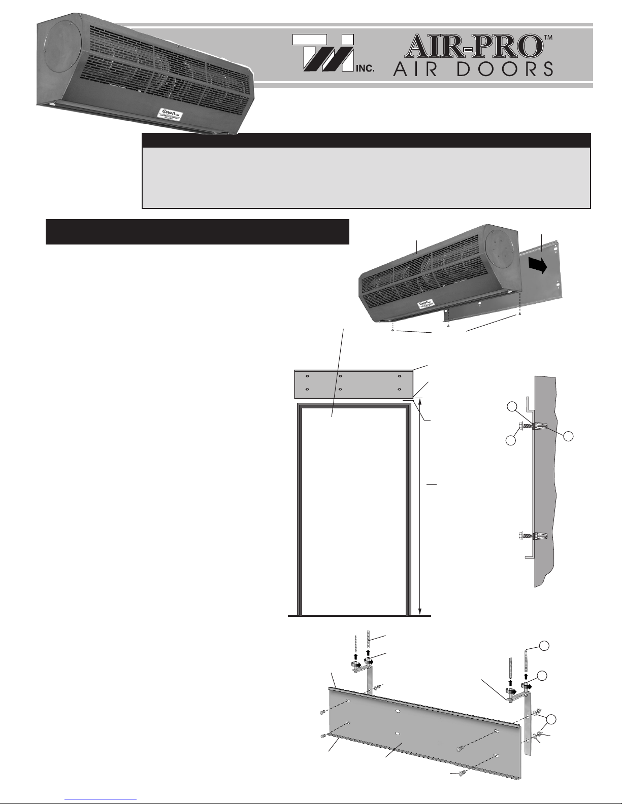
1. Remove the mounting plate locking screws from the back bottom corners of
the unit and detach the mounting plate from the back of the unit. Figure 1.
2. Keeping the mounting plate level, center it over the doorway opening. Be sure
the lipped edge of the plate is at the top. Figure 2. Note: The bottom edge of
the mounting plate should be no more than 108'' from the floor.
Never install your Air-Pro Air Door in an adverse environment,
such as, near splashing water, excess steam, explosive or
corrosive gases.
3. Mark the pre-drilled holes, remove the plate and check to
make sure you are tying into firm supporting material, i.e.
studs, header or block. Note: There should be at least 4
secure mounting holes used. If not, drill 4 new holes in the
mounting plate to accommodate a secure attachment. Drill the
wall holes.
4. Attach the mounting plate. (Screws not supplied)
Solid Wall Mounting
1. Perform the first two steps under “Wall Mounting” (see above).
2. Mark the 4 outside pre-drilled holes and remove the plate.
3. Drill the 4 anchor holes and place anchors in each hole.
Figure 3.
4. Attach the mounting plate. (Screws not supplied) Figure 2
Figure 3
1
BEFORE PROCEEDING, PLEASE READ AND SAVE THESE INSTRUCTIONS
If the Air Door unit
has been damaged in
shipping, immediately
notify the transport
company.
MOUNTING (Interior Applications) Air Door
Assembly
Locking
Screws
Mounting
Plate
Mounting
Brackets
Threaded Rods
Bracket Collars
Lipped Edge
Smooth Edge
Pre-Drilled Mounting Holes
No more
than 86''
from
the floor
Mounting
Plate
Figure 1
Mounting Plate
FLOOR
DOORWAY
OPENING
INSTALLATION INSTRUCTIONS
2
3
1
2
3
4
Figure 4
Ceiling Mounting
If mounting the air door to the ceiling is necessary, you will need to
order our mounting brackets (optional). Also, 4 threaded rods
(supplied by others) will be needed.
1. Secure the 4 threaded rods to the ceiling at the proper distance
from the floor taking the height of the air door unit into consideration.
2. Using a hex bolt, washer and nut, attach each bracket to the
mounting plate using the pre-drilled holes. Make sure the
lipped edge of the plate is at the top.
3. Holding the assembly in place, fasten the rods to the
bracket collars. Figure 4.
Hex Bolt
Nut
Washer
Lipped
Edge
Smooth
Edge
•
Not to
exceed 3''
By dropping the Air Door on its side during shipping the blower wheels may come out of the side bushing. This must be corrected prior
to operating the unit. 1) Remove the intake grill and the four screws on the side of the unit to remove the end plate. 2) Loosen the
screw that attaches the blower wheels to the motor shaft and remove the blower wheels. 3) Insert the metal wheel from the end of the
blower wheels into the rubber bushing. 4) Slide the blower wheels into the side of the unit over the motor shaft and reattach the four
screws to the side of the unit. 5) Tighten the blower wheels to the motor shaft and replace the intake grill.
IMPORTANT
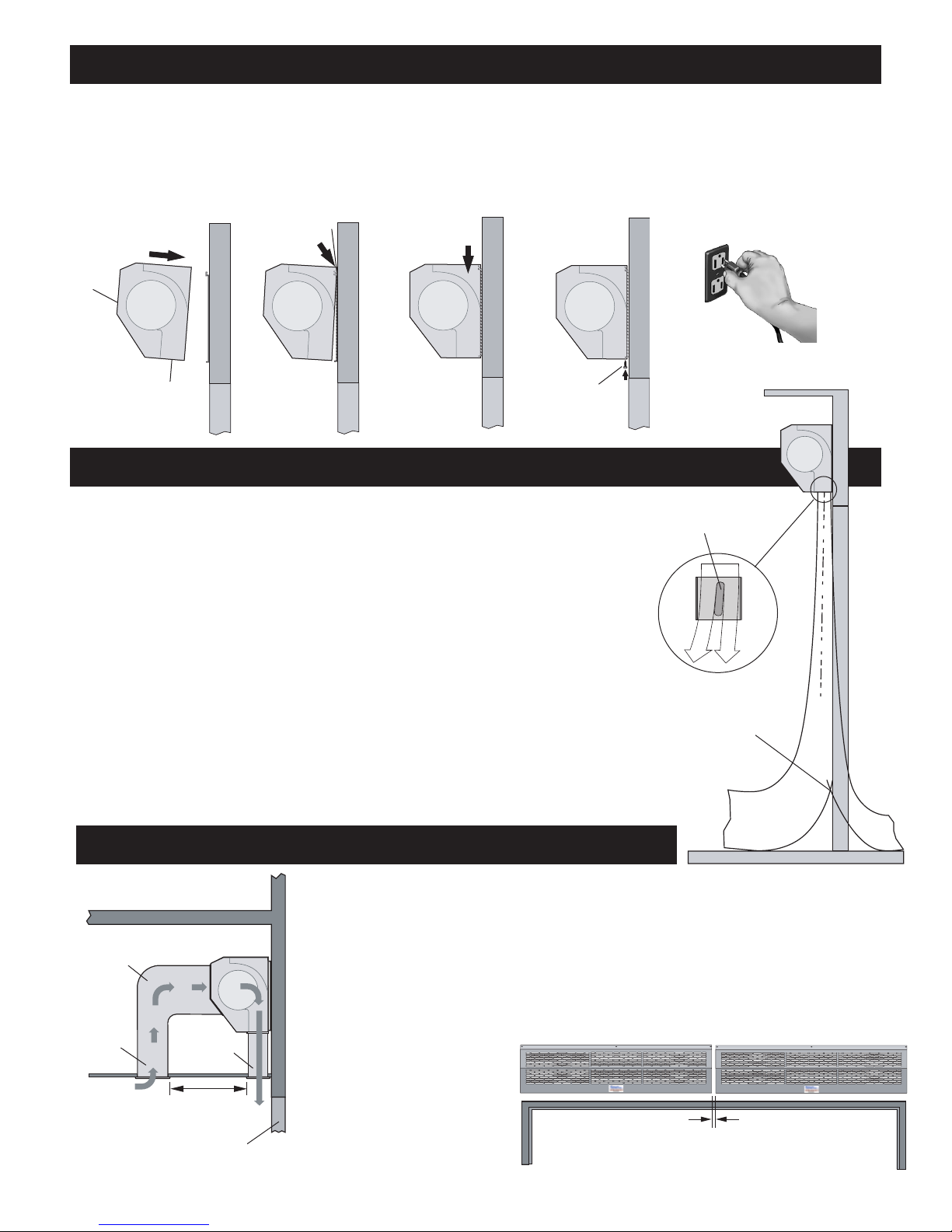
Once your air door has been installed, it will be necessary to adjust the air flow. With the door
all the way open, turn the unit on “High,”, find the air stream split by holding a square piece of
light weight cloth by its corners in the stream of air and move it back and forth (inside and
outside), approximately 6" from the floor. The cloth will show the flow pattern and will allow
you to make the proper adjustments to the directional vane for maximum efficiency. If your unit
is properly adjusted, the split should be just outside the threshold with the top of the air
current being about 2' from the floor.
The air flow angle can easily be adjusted by turning the directional vane using your hand. No
tools are needed. The angle of the air flow depends on the height of the door and is normally
between 5° and 10°.
It should never exceed 20°.
If the air current is too severe or exceeds the 2' level, you can turn the power switch to “Low.”
ADJUSTMENTS
MOUNTING
2
Attaching the Air Door to the Mounting Plate
After the Mounting Plate had been securely attached using one of the mounting methods, the air door must be attached to the mounting plate.
1. Lift the unit, into place
with the outlet nozzle
at the bottom and the
intake grill facing
away from the
mounting plate.
2. Slip the unit over the
mounting plate lip.
3. Gently push the
unit down so it
rests on the lip.
4. Replace all the
mounting plate
screws and firmly
tighten.
4. Plug the unit
into a properly
grounded 3
prong, 120 V
electrical outlet.
Directional
Vane
Intake
Grill
Outlet
Nozzle
Mounting
Plate
Lip
Mounting
Plate
Screws
2' Air Flow
Split
SPECIAL APPLICATIONS
Mounting Above the Ceiling
1. Mount the Air Door using the “Wall Mounting” method (see page 1).
2. The intake vent should be at least 36'' away from the outlet vent.
3. It is extremely important to fabricate the intake ductwork so it encapsulates the
entire intake grill. Figure 5.
1. Mount the Air Doors using any
of the mounting methods
(see page 1).
2. The space between units
should be between 1'' and 2''.
Figure 6.
Mounting Tandem Units
Figure 5
Intake
Vent
Intake
Ductwork
CEILING
DOORWAY
OPENING
Outlet
Vent
DOORWAY
OPENING
1''- 2''
AT LEAST 36''
Figure 6
3
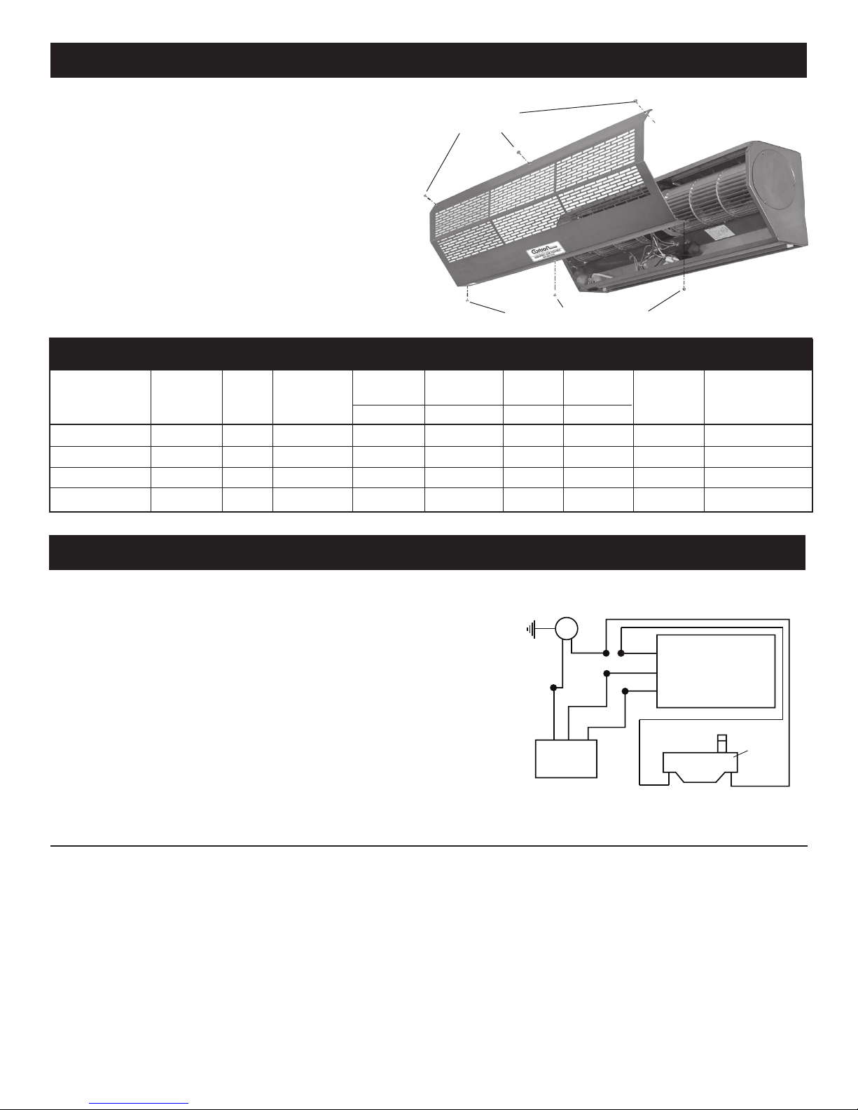
Once a year the air door‘s internal parts should be cleaned and
serviced.
CAUTION: Electric Shock Hazard
Disconnect the power line before working on any unit.
1. Loosen the intake grill mounting screws and remove the grill.
2. Vacuum inside the cabinet and around the fan baskets. Check
for any potential problems and perform any appropriate service.
3. Using mild soap and water, wipe the intake grill, directional vane
and units housing with a damp cloth.
4. Replace the intake grill and plug-in the unit.
CAUTION: Electric Shock Hazard
Unplug the power line before working on the unit.
1. Remove the front intake grill.
2. Use the knock out on one side of the Air-Pro Air Door.
Use only one knockout (which would be the closest
to the installation of the door plunger switch).
3. Install the door plunger switch at the door opening
4. Wire the plunger switch according to the diagram to the right.
5. Replace the front intake grill.
6. Plug in the Air-Pro Air Door.
CLEANING and MAINTENANCE
AUTOMATIC DOOR PLUNGER SWITCH INSTALLATION (Optional)
NOTES:
© Copyright 2011 TMI inc. Catalog No. CAPAD-1/11
Intake Grill
Mounting Screws
Intake Grill Mounting Screws
Maximum Maximum Sound Air
Diameter of Capacity (kW) Air Speed (fpm) Level (dBA) Volume (cfm) Net Dimensions (in.)
Model of Wheel (in.) Voltage Frequency (Hz) Hi Low Hi Low Hi Low Hi Low
Weight. (lbs.) L x W x H
IBD-2-36-1-SS 5.5 110-120 60 .50 .495 3149 2559 69 67 1212 989 43 36''x 8.5''x10''
IBD-2-42-1-SS 5.5 110-120 60 .65 .645 3149 2559 71 69 1353 1101 47 40''x 8.5''x10''
IBD-2-48-1-SS 5.5 110-120 60 .65 .645 3149 2559 73 71 1860 1513 53 48''x 8.5''x10''
IBD-3-60-1-SS 5.5 110-120 60 .80 .795 3149 2559 75 73 2325 1889 62 60''x 8.5''x10''
TECHNICAL SPECIFICATIONS
POWER
MOTOR
OPTIONAL
DOOR PLUNGER
SWITCH
3
2
1
3 - POSITION
HIGH/LOW
SWITCH
BLACK
WHITE
BLUE
WHITE
BLUE
BLACK
WHITE
BLACK
BLACK
BLUE
This manual suits for next models
3
Table of contents
Popular Air Conditioner manuals by other brands

Fujitsu
Fujitsu ASYG 09 LLCA installation manual

York
York HVHC 07-12DS Installation & owner's manual

Carrier
Carrier Fan Coil 42B Installation, operation and maintenance manual

intensity
intensity IDUFCI60KC-3 installation manual

Frigidaire
Frigidaire FAC064K7A2 Factory parts catalog

Sanyo
Sanyo KS2432 instruction manual


Mitsubishi Electric
Mitsubishi Electric PUHZ-RP50VHA4 Service manual

Panasonic
Panasonic CS-S18HKQ Service manual

Panasonic
Panasonic CS-E15NKE3 operating instructions

Gree
Gree GWH18TC-K3DNA1B/I Service manual

Friedrich
Friedrich ZoneAire Compact P08SA owner's manual

Daikin
Daikin R32 Split Series installation manual