TMI Products 49-85 User manual
49-85/86/87
1
Rev.E
TESTING MACHINES, INC.
The Finest Test Equipment for all Industries
49-85/86/87 MICROMETERS
PLEASE READ BEFORE OPERATING UNIT
digital-micrometer-ld3581-49-86-m44.pdf 1digital-micrometer-ld3581-49-86-m44.pdf 1 15-6-2020 14:37:3215-6-2020 14:37:32

49-85/86/87
2
Rev.E
TESTING MACHINES, INC.
The Finest Test Equipment for all Industries
Worldwide Headquarters
Sales and Service
40 McCullough Drive
New Castle, DE 19720 USA
Phone: 302-613-5600
Toll Free: 800-678-3221
Fax: 302-613-5619
www.testingmachines.com
Dear Valued Customer:
You are now the proud new owner of quality physical testing equipment manufactured by Testing
Machines Inc., the industry’s leader for over 80 years. TMI has a long-standing commitment to
quality products and customer satisfaction.
To aid in setup, calibration, and operation of all Testing Machines Inc. equipment, we offer
telephone assistance by our Technical Support Department, available Monday through Friday
from 8:30 AM to 5:00 PM EST. TMI also offers on-site Preventative Maintenance and Calibration
service.
Please take the time to fill out the postage paid Warranty Card completely and return it to us.
Your comments make it possible for us to evaluate how well we are servicing your needs.
In the unlikely event that your equipment requires warranty repair service, or if you need to
arrange for non-warranty repair service, please follow the instructions on the repair policy page
located in this manual. Supplying the requested information on the repair policy page enables
our Technical Support Staff to service your needs faster.
Please contact us at (302) 613-5600 if additional information is required.
Sincerely,
Testing Machines, Inc.
digital-micrometer-ld3581-49-86-m44.pdf 2digital-micrometer-ld3581-49-86-m44.pdf 2 15-6-2020 14:37:5815-6-2020 14:37:58

49-85/86/87
3
Rev.E
IMPORTANT SAFETY INSTRUCTIONS
Read all of these instructions carefully before operating the instrument.
1. Save these instructions for future reference.
2. Follow all warnings and instructions that are marked on the instrument.
3. Unplug the instrument from the wall outlet before cleaning. Wipe the outside surfaces with a damp cloth
only.
4. Do not use this instrument near water.
5. Do not place the instrument on an unstable cart, stand, or table.
6. Only operate the instrument from the type of power source indicated on the label.
7. For safety, this product is equipped with a three-wire grounding type plug. This plug will only fit into a
grounding type power outlet. If you are unable to insert the plug into the outlet, contact your electrician to
replace the outlet with the proper type. Do not defeat the purpose of the grounding-type plug.
8. Do not allow anything to rest on the power cord. Do not locate this product where persons will walk on the
cord.
9. If an extension cord is used with this product, make sure that the total ampere ratings of the product(s)
plugged into the extension cord do not exceed the extension cord ampere rating. Extension cords must have a
minimum insulation rating of 600v.
10. Do not remove any panels from the tester. Never push objects of any kind into any openings in the
instrument’s covers. Failure to heed this warning could result in fire or electric shock. Never spill liquid of
any kind on the instrument.
11. Do not attempt to service this product yourself. Opening or removing
covers may expose you to dangerous high voltages.
12. At the end of its service life, dispose of the product according to the relevant statutory regulations.
13. Refer all servicing to Testing Machines’ Technical Support Staff:
Testing Machines Inc.
Customer Service Department
40 McCullough Drive
New Castle, DE 19720 USA
Phone: (800) 678-3221 or (302) 613-5600
Fax: (302) 613-5619
Email: responsecenter@testingmachines.com
Web: www.testingmachines.com
14. Unplug the unit from the wall outlet and refer servicing to qualified service personnel under the following
conditions:
i When the power cord or plug is damaged or frayed.
i If liquid has been spilled into the product.
i If the product has been exposed to rain or water.
15. Adjust only those controls that are covered by the operating instructions. Improper adjustments of other
controls may result in damage to the instrument and will often require extensive work by a technician to
restore the unit to normal operation.
digital-micrometer-ld3581-49-86-m44.pdf 3digital-micrometer-ld3581-49-86-m44.pdf 3 15-6-2020 14:37:5915-6-2020 14:37:59

49-85/86/87
4
Rev.E
16. Back-up Battery:
Inside the Instrument tester a CR2032 type coin battery is used on the microcontroller
PCB to provide the necessary power to the timekeeping memory chip of the instrument during the power off
period. This to maintain the clock, calendar and setup information.
When the battery is worn out it may only be replaced by a trained service engineer!
When the battery is worn out dispose it under the ordinance of each local government or the law issued by
relating government.
The battery contains organic electrolyte.
In case of electrolyte leakage from the battery, and an eventual contact with this electrolyte to the operator
the actions described below are required.
In case of eye contact:
Flush the eyes with plenty of clean water for at least 15 minutes immediately, without rubbing. Take a
medical treatment. If appropriate procedures are not taken, this may cause an eye irritation.
In case of skin contact:
Wash the contact areas off immediately with plenty of water and soap. If appropriate procedures are not
taken, this may cause sores on the skin.
In case of inhalation:
Remove to fresh air immediately. Take a medical treatment
In case of electrolyte leakage, take it up with absorbent cloth.
This may only be done by a trained service engineer!
17. Instrument Labels:
The following labels can be found on the instrument.
Earth (Ground)
Electrical Shock Warning
Consult the Operator’s Manual
digital-micrometer-ld3581-49-86-m44.pdf 4digital-micrometer-ld3581-49-86-m44.pdf 4 15-6-2020 14:37:5915-6-2020 14:37:59

49-85/86/87
5
Rev.E
Table of Contents
INTRODUCTION ........................................................................................................................................ 6
APPLICATION ............................................................................................................................................ 6
SPECIFICATIONS ...................................................................................................................................... 6
LIST OF EQUIPMENT ............................................................................................................................... 7
CALIBRATION GAUGE ............................................................................................................................ 7
FEATURES ................................................................................................................................................... 7
NAME AND FUNCTION OF PARTS ....................................................................................................... 8
SETUP ..........................................................................................................................................................12
OPERATION ...............................................................................................................................................12
INTRODUCTION .......................................................................................................................................16
PARALLELISM CHECK/ADJUSTMENT ..............................................................................................16
STATISTICS ………………………………………………………………………………………..……. 15
SERIAL DATA OUTPUT …………………………………….……………………...…………………. 15
MAINTENANCE ........................................................................................................................................18
digital-micrometer-ld3581-49-86-m44.pdf 5digital-micrometer-ld3581-49-86-m44.pdf 5 15-6-2020 14:37:5915-6-2020 14:37:59

49-85/86/87
6
Rev.E
OPERATING INSTRUCTIONS
FOR
DIGITAL MICROMETERS
49-85,86,87 SERIES
INTRODUCTION
The TMI Digital Micrometer 49-8X Series measures the thickness of sheet material in the following
ranges:
Depending on the Model
49-85 and 49-86
0-0.050 in (Imperial Units)
0-1.27 mm (SI Units)
49-87
0-0.500 in (Imperial Units)
0-12.7 mm (SI Units)
The TMI Digital Micrometers – 49-8X Series combines a precision thickness measuring system with a
digital readout. The motor-driven instrument utilizes the dead weight micrometer principle. Each unit
has been designed and manufactured for use where the utmost precision is required, completely free of
operator influence.
The instrument consists of a heavy, solid frame which supports the unit and houses the thickness
measurement transducer and associated circuitry. A digital readout is provided to automatically
display the actual specimen thickness. The lower anvil as well as a movable pressure foot is made from
lapped, stainless steel.
APPLICATION
The TMI Micrometer is designed to measure the thickness or caliper of paper sheets, films and foils.
Almost any material including paper, natural or synthetic fabrics, leathers, metals, plastics and rubber
thickness can be measured with precision and accuracy. The 49-86 and 49-87 models also feature an
on board statistics package that stores up to 100 readings, calculates and displays the average, standard
deviation, maximum and minimum of the readings that are stored in the instrument’s temporary
memory.
SPECIFICATIONS
Dimensions: 7 in. (15cm) wide x 12 in. (30.5cm) high x 9.5 in. (24cm) deep
Approximate Weight: 22 lb. (10kg)
Power Requirements: 90-264VAC, 50/60 Hz
Ranges of Measurement: For Models 49-85 and 49-86:
Imperial Units; 0-0.050 in. x 0.0000254 in. resolution
SI Units; 0-1.270mm x 0.0005mm resolution
For Models 49-87:
Imperial Units; 0-0.50 in. x 0.0000254 in. resolution
SI Units; 0-12.70mm x 0.0005mm resolution
digital-micrometer-ld3581-49-86-m44.pdf 6digital-micrometer-ld3581-49-86-m44.pdf 6 15-6-2020 14:37:5915-6-2020 14:37:59

49-85/86/87
7
Rev.E
Available Accessories: For Models 49-85 and 49-86:
TMI # 35-12-02 Gauge Blocks for accurate calibration
(.010 in./.254mm, .020 in./.508mm, .030 in./.762mm, .040 in./1.016mm
and .050 in./1.270mm in thickness)
For Models 49-87:
TMI # 35-12-03 Gauge Blocks for accurate calibration
(0.010 in./.254mm, .100 in./2.54mm, .200 in./5.08mm,
.300 in./7.62mm, .400 in./10.16mm and .500 in./12.70mm in thickness)
STANDARDS
TAPPI T 411, ISO 534, DIN 53105, ISO 3034, APPITA 1301.426, PAPTAC D.4, ISO 12625-3,
ISO 037, ASTM F2251, ISO 5084
NOTE: Only the 49-8X configured with the appropriate pressure foot and dead weight is capable
of meeting above standards
LIST OF EQUIPMENT
x 1 TMI Digital Micrometer
x 1 Instruction Manual
x 1 Box with Packing Material
NOTE: Carefully check all small wrappings, boxes, and envelopes to be sure all parts and supplies
are accounted for.
CALIBRATON GAUGE
To check the calibration properly, the user of the micrometer should have the necessary gauge
blocks on hand. The gauge blocks can be ordered separately from TMI. See Section 3 –
Specifications.
SAVE THE BOX
Remove the micrometer from the case with the greatest of care. Do not use
the pressure foot, the anvil or the spindle as a handle. Grasp the instrument
by the base only.
Please save all the original packing material from the micrometer. In the event the tester needs to
be returned, it must be packaged in the original shipping carton after receiving approval and a
Return Authorization Number (RA#) from TMI’s Customer Service Department.
FEATURES
x Digital readout and superior mechanical design
x Serial output for simple data collection
x Compact, for use throughout the laboratory and production floor
x Special anvil diameters and dead weight loads available on request
digital-micrometer-ld3581-49-86-m44.pdf 7digital-micrometer-ld3581-49-86-m44.pdf 7 15-6-2020 14:37:5915-6-2020 14:37:59

49-85/86/87
8
Rev.E
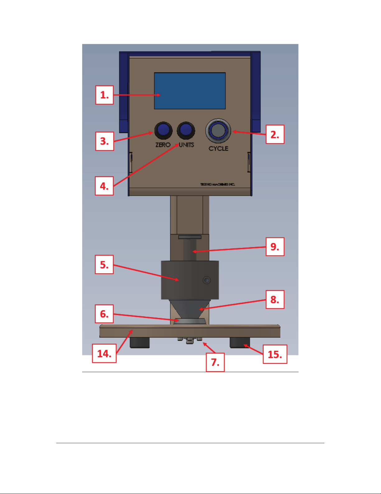
NAME AND FUNCTION OF PARTS
All the part names and their descriptions that are listed below can be found in Figure 1 and Figure 2...
for Model #’s 49-85, 49-86, and 49-87.
1. Display Window: The digital display window shows the thickness of the specimen measured.
2. Cycle Button: This Button is located on the front right side, a blue illuminated push button
switch. This button stops the anvil spindle and pressure foot from moving.
3. Zero Button: Pressing this will tell the machine to zero itself the next time that it comes to rest
on the lower platen or other static object. (In Menus this button will move the highlighted area
between different options.)
4. Units Button: This button is located on the middle of the front panel. In the 49-85 instrument,
this button will cycle the units through μm, mils, millimeters, and inches. (In Menus this button
will cycle through available options for the highlighted setting or accept the selected command
depending on the menu.) In the 49-86 and 49-87 instruments, the UNITS button is used to access
and navigate through the statistics pages as well as the Menus page.
5. Split Weight: TMI # 49-76-00-15 (Standard Model, 2 pieces of the afore mentioned part number
make this weight)
6. Lower Anvil: A testing surface that is optically flat. The specimen is placed on the anvil’s
surface and when the pressure foot comes down, a reading is obtained.
a. TMI # 49-01-07-016 (Standard Unit)
7. Set Screws: The three set screws are for the parallelism adjustment. (3) 10-32 x 5/8 set screws.
8. Pressure Foot: This part will move up and down once the machine is operating. The pressure
foot is the part that comes down on the specimen when the actual measuring is being performed.
TMI # 49-60-01-049 (Standard model)
9. Anvil Spindle: The spindle anvil will move up and down carrying the weight and pressure foot
with it.
10. On/Off Switch: The main power is switched on and off on this unit by a switch located on the
back on the unit built into the power entry module.
11. Serial Output: This unit has been fitted with RS-232 output via a Mini USB connector.
a. Serial Communication Parameters
A Null Modem is not required
i. Baud: 9600 bps
ii. Data Bits: 8
iii. Parity: None
iv. Stop Bits: 1
v. Flow Control: None
12. AC Line Cord Connection: The style of the line cord that is supplied with the unit is decided by
the country that the unit is being used.
digital-micrometer-ld3581-49-86-m44.pdf 8digital-micrometer-ld3581-49-86-m44.pdf 8 15-6-2020 14:37:5915-6-2020 14:37:59

49-85/86/87
9
Rev.E
13. Fuse: 0.25 Amps. TMI # 680-075
a. Fuse Drawer: TMI # 680-062
b. (The Fuse is located inside the Fuse Drawer. you must depress two tabs, one on either
side, on the fuse drawer to remove it.)
Note:
In case of a blown fuse it needs to be replaced by one that has the identical
shape and the same current rating. In this case always disconnect the
power cord from the AC power inlet of the instrument before opening the
fuse holder.
Do not use fuses with a higher current rating then the original as this can cause damage to the instrument!
The use of repaired fuses, and/or short circuiting the fuse holder is prohibited!
14. Base Plate: The solid plate that the machine stands on.
15. Rubber Foot: To make sure the machine stands flat and secure on the ground; the machine has
four rubber spacing feet. TMI # 240-001
digital-micrometer-ld3581-49-86-m44.pdf 9digital-micrometer-ld3581-49-86-m44.pdf 9 15-6-2020 14:37:5915-6-2020 14:37:59
49-85/86/87
10
Rev.E
Figure 1.
digital-micrometer-ld3581-49-86-m44.pdf 10digital-micrometer-ld3581-49-86-m44.pdf 10 15-6-2020 14:37:5915-6-2020 14:37:59

49-85/86/87
11
Rev.E
Figure 2.
11.
10.
13.
12.
digital-micrometer-ld3581-49-86-m44.pdf 11digital-micrometer-ld3581-49-86-m44.pdf 11 15-6-2020 14:37:5915-6-2020 14:37:59
49-85/86/87
12
Rev.E
SETUP
1. Take the micrometer out of the box and place it on a rigid, level bench top, free from large
temperature variations, excessive air currents and vibration. Ensure there is appropriate clearance
from the rear of the instrument to easily operate the power shutoff device.
2. MAKE SURE TO REMOVE THE SHIPPING COLLAR FROM THE ANVIL SPINDLE.
(The Shipping collar is typically a plastic tube secured by a large cable tie).
3. If included, mount the Split Weight to the micrometer spindle using the included 9/64” Allen
Wrench. (Split Weights are removed for shipping)
Note:
Please handle the split weights with great care to avoid damage. The edges of the split weights can
have sharp edges. Please be aware of the possible danger of cutting yourself!
4. Remove the rubber pad that is located in between the anvils during shipment.
(If the machine has a range of 0.000”-0.050” you will have to gently lift upper anvil enough
to slide the pad out).
5. Connect the power cord from the power entry module (located on the back of the unit) to a
suitable AC outlet, free from electrical noise and large voltage variations.
Warning:
If the supplied power plug needs to be adapted to the local power requirements this must be done by a
qualified electrical engineer. The plug must be equipped with a safety earth terminal.
Please Note:
Power cord wire colors:
Brown or Black = Line
Blue or White = Neutral
Yel/Grn or Green = Earth/Ground
OPERATION
1. Ensure that the shipping collar has been removed from the unit. Serious damage can occur if
the shipping collar has not been removed.
2. Turn the power switch to the “On” position. At this time, the display and start/stop button will
become illuminated. The first screen will only show until the end user confirms that they have
removed the restraints. TMI is not liable for damage cause by disregarding this warning.
3. The second screen will now appear. The machine will need to run 2 to 3 cycle to find the limits of
its travel. This is done by pressing the Units button. While cycling, the blue LED button should
pulse.
4. The third screen will remind you to clean the anvils for optimal performance. Draw a piece of
soft-body paper through the pressure foot and anvil; this will remove any foreign matter. Also
visually inspect the anvil surfaces for any debris, it might be necessary to use a small amount of
rubbing alcohol to clean them.
digital-micrometer-ld3581-49-86-m44.pdf 12digital-micrometer-ld3581-49-86-m44.pdf 12 15-6-2020 14:37:5915-6-2020 14:37:59

49-85/86/87
13
Rev.E
5. The fourth screen to appear will be the main testing screen. It displays the measured gap, the
units, and the time. For best results, allow the micrometer to warm up for approximately 30
minutes minimum before performing any tests. It is highly recommended to always zero the
instrument before running samples.
6. Zero the Micrometer: To zero the micrometer, press the Zero button on the front panel.
Pressing this will tell the machine to zero itself the next time that it comes to rest on the lower
platen or other static object.
7. If you wish, you can perform a quick check of your micrometer. This is done with the TMI Gauge
Blocks:
For Model 49-85 and 49-86:
TMI # 35-12-02
For Model 49-87:
TMI # 35-12-03
Slip one of the gauge blocks between the pressure foot and the anvil. Ensure that the gauge block
is located at the visual center of the anvils. The digital display reading should be the same as the
thickness of the gauge block. (See the instrument’s calibration record for tolerance.) If the
micrometer does not give the correct reading of the gauge block, calibrate the micrometer. (See
Section 9 – Calibration of the micrometer.)
8. All samples that are to be tested should be prepared and conditioned according to TAPPI T400 or
applicable standards. Each sample should be cut and prepared as described in TAPPI T411 or any
other applicable standard. Any samples that are kinked, bent or creased should not be used since
this may affect the reading of the sample.
9. Measure the thickness by placing the specimen between the automatically cycling pressure foot
and the anvil when they are apart. Ensure that the specimen fully covers the area of contact
between the pressure foot and the anvil. During the time when the pressure foot rests on the
specimen, the specimen's thickness is measured and displayed on the digital readout. At the end
of the cycle time, the pressure foot again moves upward and a new measurement can be made. Be
sure to only take one reading at one point on the specimen.
Special Notes on Operation:
- Readings that appear to be slightly out of tolerance have a high likelihood of being caused by
trace amounts of debris left on the surfaces of the anvils.
USER OPTIONS MENU (49-86 and 49-87 only)
You may enter the User Options Menu from the main screen by pressing and holding the Units
Button and pressing the Zero Button. This menu contains the following options:
Password Protection (optional)
The instrument’s Options Menu can be protected by a “manager” password if the user chooses to
do so. The default setting for the instrument is 0-0-0-0, which disables the password prompt. To
enable a password, select the option and input a 4-digit code other than 0-0-0-0.
Note: If you would like to reset the password, use the calibration password. This will reset the
password to the factory default (disabled).
digital-micrometer-ld3581-49-86-m44.pdf 13digital-micrometer-ld3581-49-86-m44.pdf 13 15-6-2020 14:37:5915-6-2020 14:37:59

49-85/86/87
14
Rev.E
Lowering Speed (in mm/s)
Your standard may specify a specific lowering speed. The options are 1, 2, and 5mm/s (10 mm/s
49-87 only)
Dwell Time (in seconds)
Your standard may specify a specific time to wait after the spindle motion stops on the sample
before it returns a result. The “0 seconds” option will report a result as soon as the machine
registers a stop. Dwell Times over 1 second will pause the motor in order to wait for the reading.
The options are 0,1,2,3,4,5, and 6 seconds.
Starting Units
This is the units that the machine will default to when powering on. The options are “μm” for
micrometers, “mils” for mils, “mm” for millimeters, and inches.
Record Stats:
The options for this setting are ON or OFF. Statistics can still be viewed if set to OFF, but no
new readings will be recorded.
Stat Threshold:
The options for this setting are OFF, 2 μm, 4 μm, and 6 μm. These are in metric because the
machine is internally a metric machine. Statistics will not be recorded if the reading is within the
tolerance band (+/-) around zero.
Zero Threshold:
This sets a small range around a reading of 0.00 to be reported as 0.00. For example: if the
machine is set to a Zero Threshold of 2 μm then any reading from -2 to 2 μm will return a reading
of 0 μm. The options for this setting are OFF, 2 μm, 4 μm, and 6 μm. These are in metric because
the machine is internally a metric machine.
Time:
This line contains several options
o 24Hr or A.M./P.M. – changes between 24 and 12 hour time
o Hours – adds one hour
o Minutes – adds one minute
o Seconds – resets the seconds to zero
Live Readings:
This option changes how the main screen displays the current gap. Turning Live Readings ON
will show a constant feed of the updated gap. Turning Live Readings OFF will cause the screen to
only update when it has a valid reading. These options will not change how the machine
communicates its readings with GraphMaster.
LED Pulse:
This will toggle the Cycle Button’s LED functions between constantly on and pulsing when a test
is being conducted. This has no effect on the machine’s function.
digital-micrometer-ld3581-49-86-m44.pdf 14digital-micrometer-ld3581-49-86-m44.pdf 14 15-6-2020 14:37:5915-6-2020 14:37:59

49-85/86/87
15
Rev.E
Return:
This saves the options and returns you to the main screen.
STATISTICS
The 49-86 and 49-87 models have a statistics feature that allows the user to display the average,
standard deviation, maximum, and minimum values of the readings stored in the instrument’s
temporary memory (this memory is erased when the power to the instrument is turned off).
1. To access the main statistics screen from the main (measurement) screen, press the UNITS button.
2. The main statistics screen will display the current reading, the average of the stored readings, the
standards deviation of the stored readings and the maximum and minimum of the stored readings.
3. Press the UNITS button again to list the readings
a. Navigate this screen by pressing the ZERO key to highlight ↑ , ↓ , DELETE, or RETURN
b. Press the UNITS key to act on the highlighted option
i. Pressing UNITS when the ↑ is highlighted will scroll the active reading selection
box up once.
ii. Pressing UNITS when the ↓ is highlighted will scroll the active reading selection
box down once.
iii. Pressing UNITS when the DELETE is highlighted will delete the active reading
in the selection box.
iv. Pressing UNITS when the RETURN is highlighted will return to the main
statistics screen.
c. Press and hold the UNITS key, then press the ZERO key to delete all readings. User
confirmation is required for this.
4. Press and hold the UNITS key, then the ZERO key to return to the Main (measurement) screen.
SERIAL DATA OUTPUT
These Testing Machine Inc. Micrometers (Thickness Gauges) output a string through a mini-USB
connector on the back panel of the instrument.
The USB host (PC) will need to be looking for serial data on one of its COM ports. The number of the
COM port will vary from host to host.
These are the settings needed to capture the serial data -
Baud rate: 9600
Data: 8 bits
Parity: None
Stop Bit(s): 1
Flow Control: None
Here are some serial string examples-
x Initial string - "CC5.1.1.13;"
o This is an identifier string used by our GraphMaster product. You can ignore it if you are
not using GraphMaster. It will only show up after powering on.
x After each cessation of downward motion, like the spindle coming to rest on a sample, the
machine will output a serial data string in the following format.
TM V00.01.02 49-87-00-000112345-67 00000000053+000004.370
o "TM V00.01.02 " - A software version number
digital-micrometer-ld3581-49-86-m44.pdf 15digital-micrometer-ld3581-49-86-m44.pdf 15 15-6-2020 14:37:5915-6-2020 14:37:59

49-85/86/87
16
Rev.E
o "49-87-00-0001" - The machine's complete model number
o "12345-67" - The machine's serial number. Yours will probably look like 8xxxx-01
o "0000000005" - An identifier for this reading. This resets to zero on powering on and
rolls over to 0 after its maximum is reached.
o "3" - The unit of the reading. '3' is mils (thousandths of an inch) and '0' is microns
(micrometers)
o "+000004.370" - The reading itself in the units just specified. The '+' is there because the
machine can show negative values if zeroed while resting on something besides the
platen.
CALIBRATION
INTRODUCTION
This machine has been adjusted and calibrated at the factory. The 49-8X series micrometer has a
large portion of its calibration done via a PC. For that reason and the highly technical nature of
the calibration we recommend that it only be performed by factory trained personnel. When
adjustments and calibration are necessary, refer to the following procedures:
1. Use a set of TMI gauge blocks when calibrating or making adjustments. The set consists of
five steel gauge blocks of different sizes. (See Section 3 – Specifications.) These gauge
blocks are checked against standards that are traceable to the NIST. The part number for the
TMI gauge blocks is as follows:
For Model 49-85 and 49-86:
TMI # 35-12-02
For Model 49-87:
TMI # 35-12-03
2. Turn the micrometer on. Allow the micrometer to warm-up for approximately one half hour
before attempting to calibrate.
3. The pressure foot and the lower anvils must be clean and free of dirt. The gauge blocks must
be cleaned thoroughly with alcohol before use. Do not touch the working surface with
fingers before making any measurements.
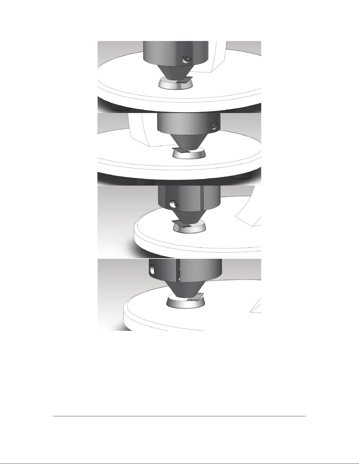
PARALLELISM CHECK/ADJUSTMENT (pictures on following page)
Adjustment of parallelism should only be made by a trained professional
1. Always check the anvil parallelism first. Insert one half of the width of the .010 in. gauge
block between the anvils on the right side of the unit and take a reading.
2. Insert the same one half of the width of the gauge block between the anvils on the left side of
the unit. See Figure 1.
3. Repeat the above procedure for the front, back and center of the anvils.
digital-micrometer-ld3581-49-86-m44.pdf 16digital-micrometer-ld3581-49-86-m44.pdf 16 15-6-2020 14:37:5915-6-2020 14:37:59
49-85/86/87
17
Rev.E
Figure 1
digital-micrometer-ld3581-49-86-m44.pdf 17digital-micrometer-ld3581-49-86-m44.pdf 17 15-6-2020 14:38:0015-6-2020 14:38:00

49-85/86/87
18
Rev.E
4. For Model 49-85 and 49-86:*
The readings must be within 0.00004 in. of each other for the anvil and the pressure foot to
be considered parallel and no adjustment needs to be done.
For Model 49-87:*
The readings must be within 0.0002 in. of each other for the anvil and the pressure foot to be
considered parallel and no adjustment needs to be done.
5. If the parallelism measurements, as described in Section 9.2 – Steps 1 and 2, do not fall
within the tolerance range, the anvil needs to be adjusted. Underneath the base plate, there
are three leveling screws that attach the anvil to the base plate. Use an Allen key to adjust
the leveling screws while securing the nut with a 3/8 in. wrench.
For Model 49-85 and 49-86:*
Adjust the leveling screws until all readings are within .00004 in. (.001 mm) across the
anvil’s surfaces.
For Model 49-87:*
Adjust the leveling screws until all readings are within .0002 in. (.005 mm) across the
anvil’s surfaces.
When the adjustments are completed, recheck the parallelism.
* For instruments 49-86-00-0003 and 49-87-00-0003 perform three sets of readings, adjusting the
screws each iteration in order to establish a baseline parallelism. Only perform this parallelism
adjustment if measurements with gauge blocks placed in the visual center of the anvil are outside
the tolerances of the instrument’s calibration record.
MAINTENANCE
The TMI Digital Micrometers – 49-8X Series do not require oiling or special maintenance. A rise in
operating temperature is expected. The temperature will rise until it reaches operating temperature.
Keep the instrument clean and in an environment that is free of dirt and dust. For consistent test
readings, it is very important that the anvil and pressure foot are kept clean.
If the instrument is not in use for an extended period of time, a plastic cover should be used to protect
it from dirt and other foreign matter. The pressure foot and the anvil should not be in contact for
extended periods of time. Place a piece of paper, film, etc. between the pressure foot and anvil.
digital-micrometer-ld3581-49-86-m44.pdf 18digital-micrometer-ld3581-49-86-m44.pdf 18 15-6-2020 14:38:0015-6-2020 14:38:00

49-85/86/87
19
Rev.E
TERMS AND CONDITIONS OF SALE
All purchases from TMI are subject to TMI’s Standard Terms and Conditions linked below. The TMI Terms
and Conditions are an integral part of each business transaction, as indicated in TMI’s price bulletins,
quotations or order acknowledgements provided.
All materials delivered, services provided, and work performed by TMI are subject to the Terms and
Conditions listed on the linked document.
To view and/or download the complete Terms and Conditions of Sale
document in PDF format, please visit:
http://www.testingmachines.com/terms-and-conditions-of-sale
digital-micrometer-ld3581-49-86-m44.pdf 19digital-micrometer-ld3581-49-86-m44.pdf 19 15-6-2020 14:38:0015-6-2020 14:38:00

digital-micrometer-ld3581-49-86-m44.pdf 20digital-micrometer-ld3581-49-86-m44.pdf 20 15-6-2020 14:38:0015-6-2020 14:38:00
This manual suits for next models
2
Table of contents
Popular Measuring Instrument manuals by other brands

KAEL Muhendislik Elektronik
KAEL Muhendislik Elektronik ENERGY 11-DIN instruction manual

GeoMax
GeoMax Zipp20 series installation guide

Tektronix
Tektronix 7853A instruction manual

National Instruments
National Instruments 9235 Getting started guide

Endress+Hauser
Endress+Hauser Tankvision Multi Scan NXA83 operating instructions

Toya
Toya VOREL 81775 Original instructions


