TMS LC-18-4CH-KP1 User manual

TMS Lite LC-18-4CH-KP1
________________________________________________________
________________________________________________________
LC-18-4CH-KP1
Lighting Controller Unit
USER MANUAL
TMS Lite LC-18-4CH-KP1
1
Table of Contents
General Description ................................................................................................................................2
Specification........................................................................................................................................2
Connectors Description...........................................................................................................................3
Operation Mode .....................................................................................................................................5
Constant Mode ...................................................................................................................................5
Strobe Mode .......................................................................................................................................5
Trigger Mode.......................................................................................................................................6
Current Multiplier ...................................................................................................................................6
Control Mode..........................................................................................................................................7
Manual Control.......................................................................................................................................8
Button .................................................................................................................................................8
Setting up using Display Panel ............................................................................................................9
Setting up TCPIP Parameters ........................................................................................................11
Input Signal ...........................................................................................................................................12
Output Signal ........................................................................................................................................12
Drawing Dimension...............................................................................................................................13
Communication Protocol ......................................................................................................................14
Revision Notes
Rev
Date/Author
Comment
1.0
July2020/KW
First Revision
1.1
Aug2020/KW
Added Communication Protocol Documentation
1.2
Dec2020/KW
Minor Correction

TMS Lite LC-18-4CH-KP1
2
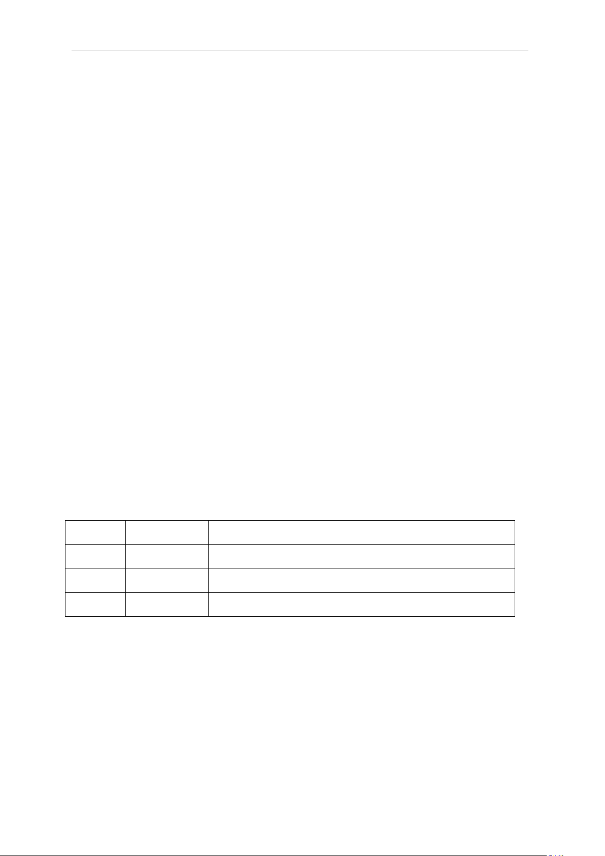
General Description
The LC-18-4CH-KP1 controller provides intensity control of LED lightings for machine vision
applications. The controller consists of 4 channels with individual settings for each channel.
There are 3 modes of operation provided to support different types of application. This
controller has built in display and keypads for manual control.
Specification
Parameter
Value
Controller Supply Voltage
24 VDC
Lighting Supply Voltage
5/12/24/48 VDC
(According to Lighting Voltage Rating)
No. of Channel
4
Channel Mode
Constant, Strobe, Trigger
Output Current
Maximum 1A per channel
Strobe Delay, Strobe Width,
Output Delay, Output Width
Adjustable 0 –99.99ms (10us/step)
Input Trigger Signal
3.3-24V, >5mA
rising/falling edge trigger
Output Trigger Signal
Support rising/falling edge output trigger
Trigger Delay
≤ 25us
Software Control
RS232 / TCPIP
Manual Control
Keypad with 7-Segment Display
TMS Lite LC-18-4CH-KP1
3
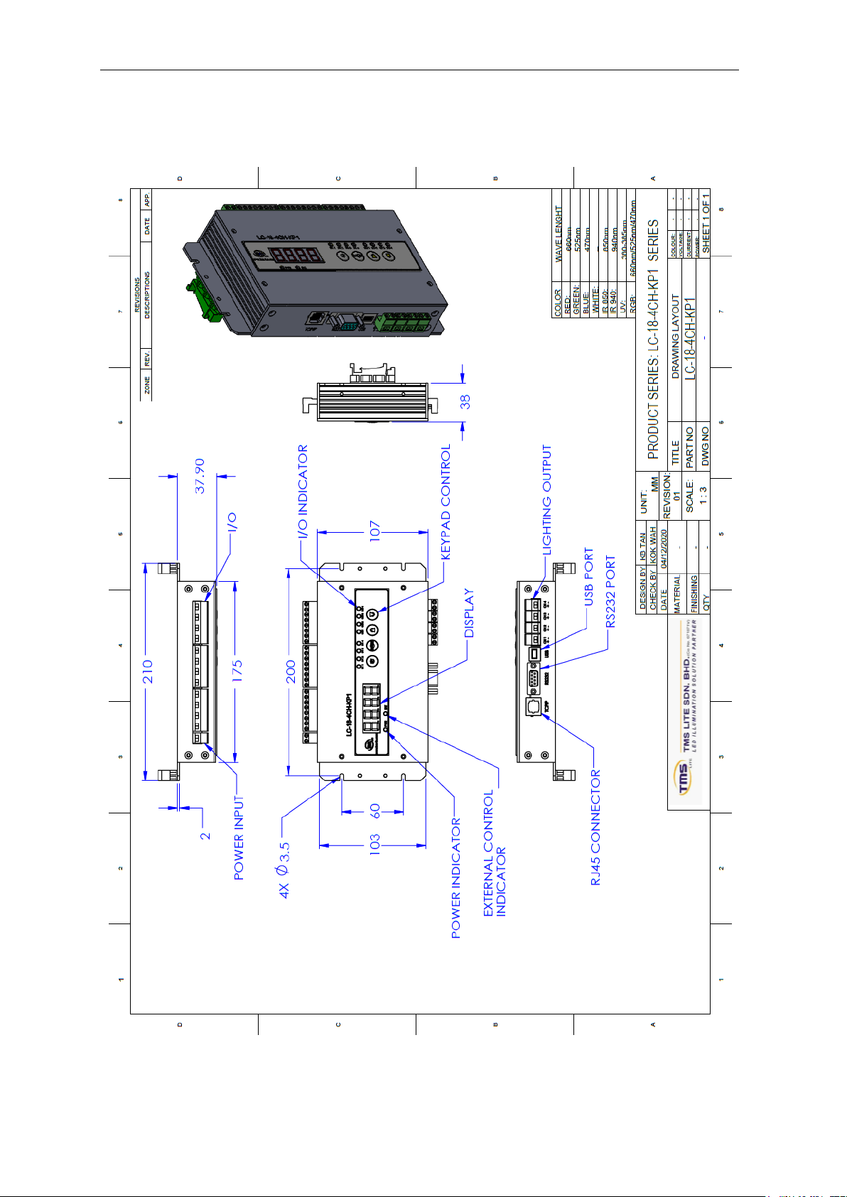
Connectors Description
Terminal
Function
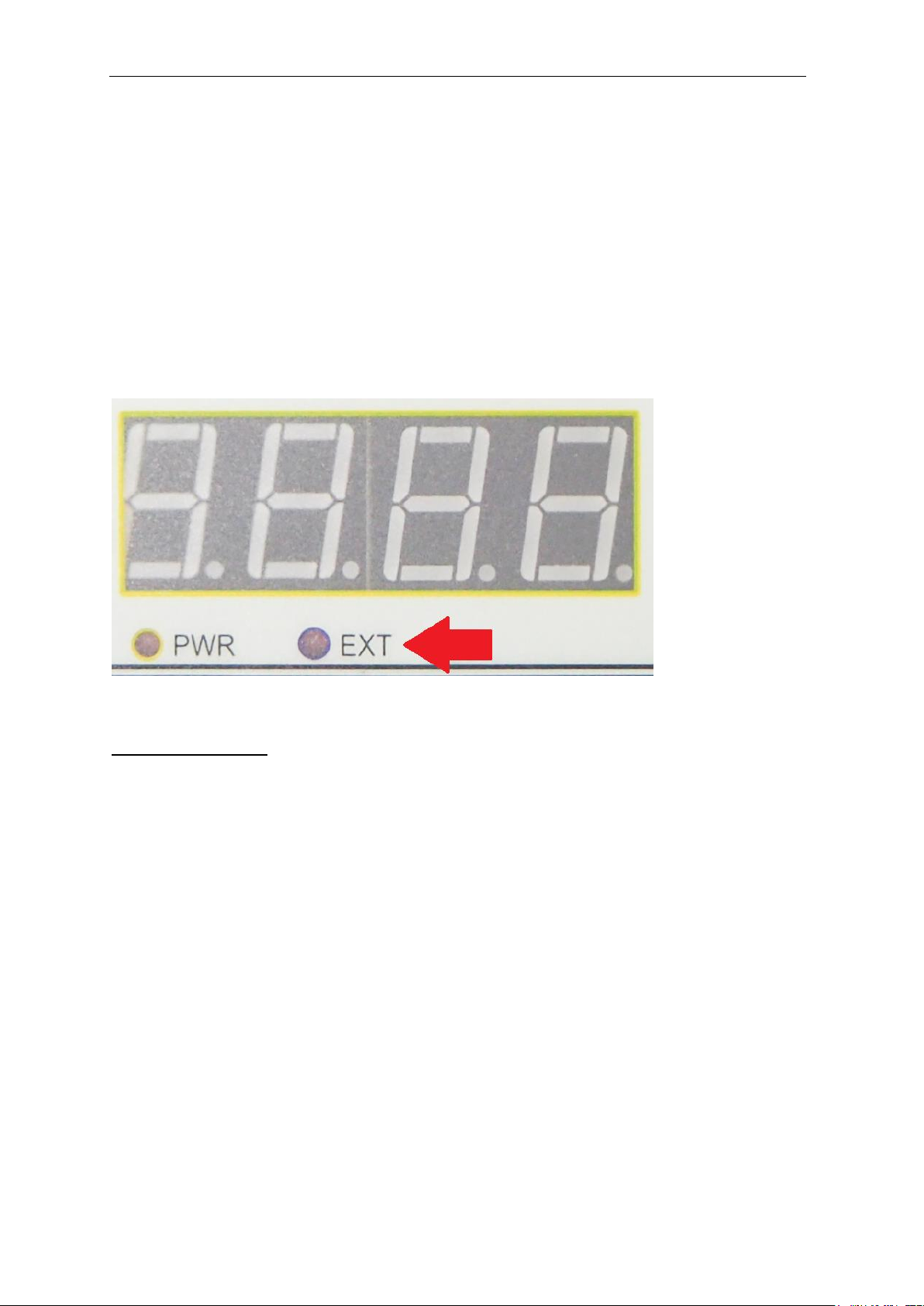
7-Segment Display
Display for manual setting
PWR Indicator
Controller power indicator
EXT Indicator
Manual/External mode indicator
Button (SET, RANGE,
UP, DOWN)
Buttons for manual setting
IN Indicator
Input signal indicator
OUT Indicator
Output signal indicator
TMS Lite LC-18-4CH-KP1
4
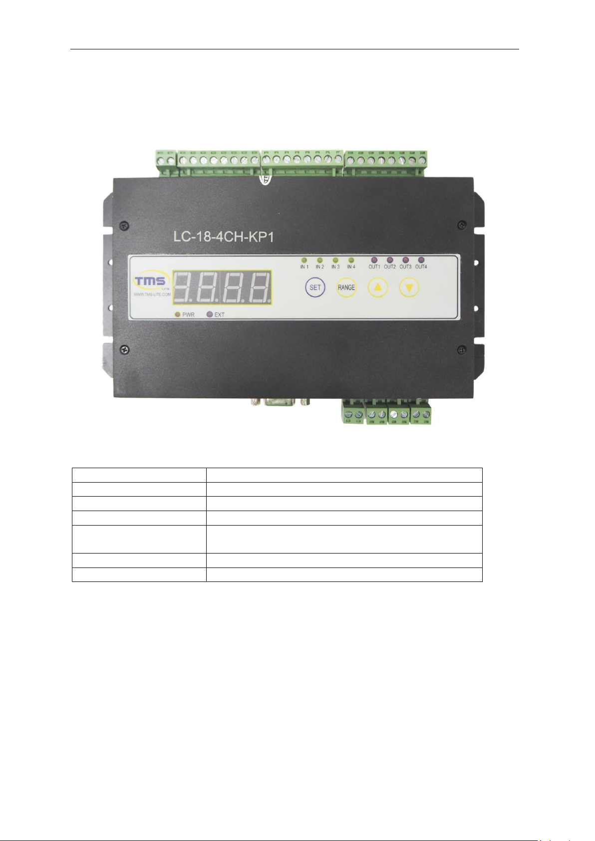
Terminal
Function
POWER INPUT +
Controller Power Supply +
POWER INPUT -
Controller Power Supply –
LIGHT INPUT +
Power Supply for Lighting +
LIGHT INPUT –
Power Supply for Lighting –
IN +
External Input +
IN –
External Input –
OUT +
External Output +
OUT –
External Output –
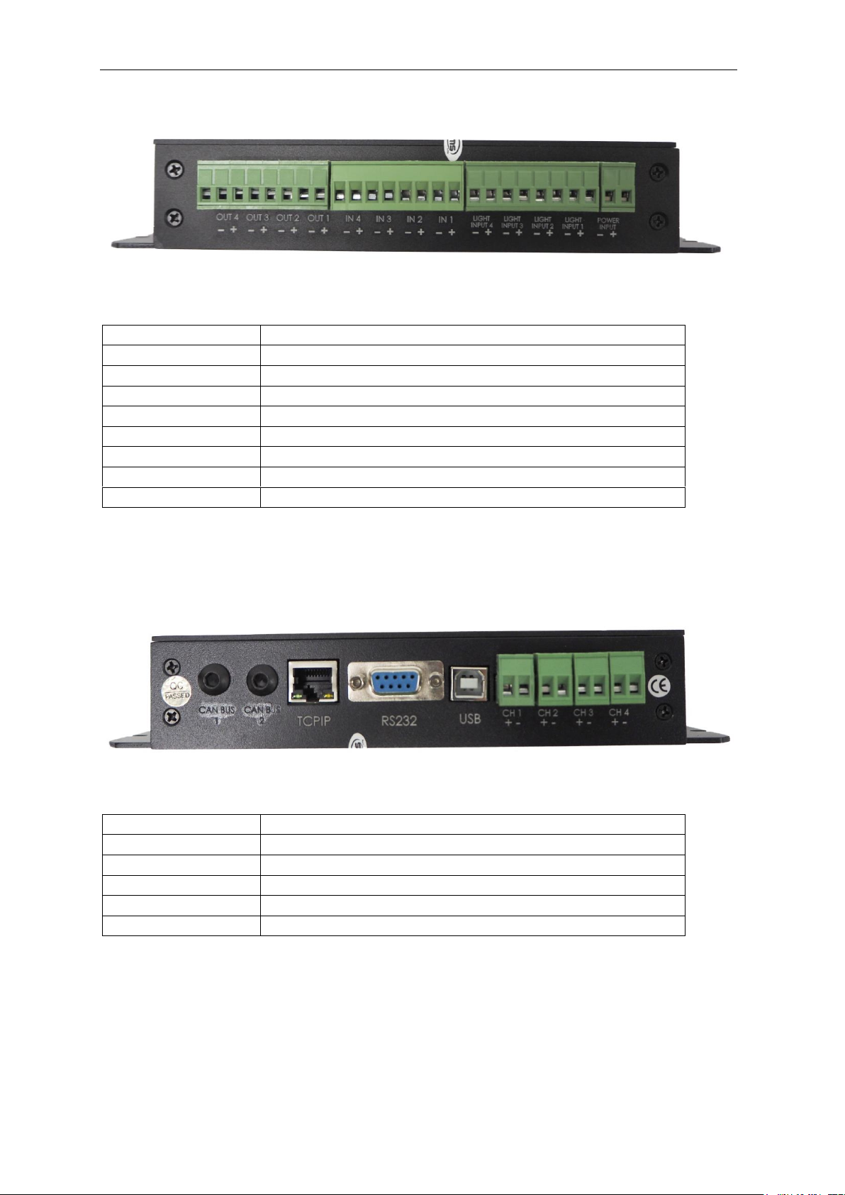
Terminal
Function
CH +
Lighting Channel Output +
CH –
Lighting Channel Output –
USB
USB Connection
RS232
RS232 Connection
TCPIP
TCPIP Connection

TMS Lite LC-18-4CH-KP1
5
Operation Mode
Constant Mode
Constant mode offers continuous lighting intensity control. Lighting intensity is controlled
using constant current technique. Brightness can be adjusted from fully off to fully on in the
range of 0 –255.
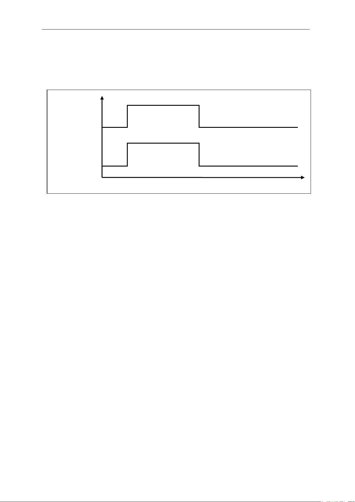
Strobe Mode
Strobe mode provides short interval triggering for applications that require high intensity and
high precision. An input trigger signal will turn on the lighting output based on pre-set delay
and duration parameters.
There are 4 adjustable strobe parameters available:
Strobe Delay = Delay time between the external input signal and the lighting output
Strobe Width = Duration of the lighting’s turn on time
Output Delay = Delay time between the external input signal and the external output signal
Output Width = Duration of the external output signal’s turn on time
Parameter timings are in the range of 0-9999 which is equivalent to 0-99.99ms (in step of 10us)
External Trigger
Lighting Strobe
Camera Output
Strobe Delay
Strobe Width
Output Delay
Output Width
TMS Lite LC-18-4CH-KP1
6
Trigger Mode
Trigger mode provides most flexibility for variable timing light output. The light output ON
when input trigger signal received and OFF when no input signal.
Current Multiplier
Current Multiplier setting provides more precise control of lighting intensity for lightings with
different current ratings.
Current Multiplier setting range = 1-10
1 = 10% of max output current (100mA)
2 = 20% of max output current (200mA)
3 = 30% of max output current (300mA)
4 = 40% of max output current (400mA)
5 = 50% of max output current (500mA)
6 = 60% of max output current (600mA)
7 = 70% of max output current (700mA)
8 = 80% of max output current (800mA)
9 = 90% of max output current (900mA)
10 = 100% of max output current (1000mA/1A)
For example: if the lighting’s current rating is 260mA, current multiplier can be set to 3, setting
the maximum output current to 300mA. So the lighting’s intensity can be adjusted from low to
high within the range of 0-255.
If multiplier is set too high, for example 10 (100% of max output = 1A), the adjustable intensity
range for the lighting is only about 0-67. Setting the intensity value to 68 or higher will not
have any effect towards the lighting output brightness.
External Trigger
Lighting Strobe
TMS Lite LC-18-4CH-KP1
7
Control Mode
The LC-18-4CH-KP1 lighting controller can be controlled using either the display panel or
external control (RS232/USB/TCPIP), but both controls cannot be used at the same time.
The LED labeled “EXT” is an indicator of which control is in use:
1) LED turned on –External control (USB/RS232/TCPIP)
2) LED turned off –Display Panel control
Switching the mode
To switch the control mode, hold down UP and DOWN button for about 1 second and observe
the change on the LED indicator.

TMS Lite LC-18-4CH-KP1
8
Manual Control
Button
In Manual Control Mode, the 4 Buttons (Set, Range, Up and Down) are used for setting the
controller’s parameter.
Button
Function
SET
Select and Set parameter
RANGE
Moving digits when setting parameter
UP
Increase parameter value
DOWN
Decrease parameter value
TMS Lite LC-18-4CH-KP1
9
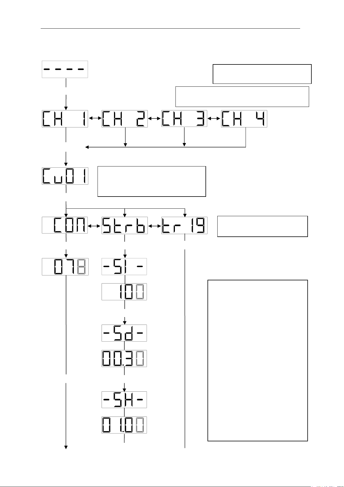
Setting up using Display Panel
Press and hold SET for about one second
Press SET`
Press SET
Press SET Press SET Press SET
Press SET
Press SET Press SET
Use UP and DOWN to select
mode (CON, STRB, TRIG)
Use UP and DOWN to select the
intensity (0 - 255) and delay
settings (0 - 99.99)
The “unit” digit is flashing. Use UP
or DOWN to change the value by
one.
Press RANGE to switch digits.
In Constant mode, only the
intensity can be set.
In Strobe mode, 5 types of
parameters can be set:
1. Strobe Intensity
2. Strobe Delay
3. Strobe Width
4. Output Delay
5. Output Width
Idle State
Strobe
Delay
Strobe
Width
Use UP and DOWN to select channel (CH1 to
CH4)
Use UP and DOWN to select the
current multiplier (1 to 10 which
equals to 10 –100% of max current)
Strobe
Intensity
Constant
Intensity

TMS Lite LC-18-4CH-KP1
10
Press SET
Press SET
Press SET
Back to Idle State
Output
Delay
Output
Width
TMS Lite LC-18-4CH-KP1
11
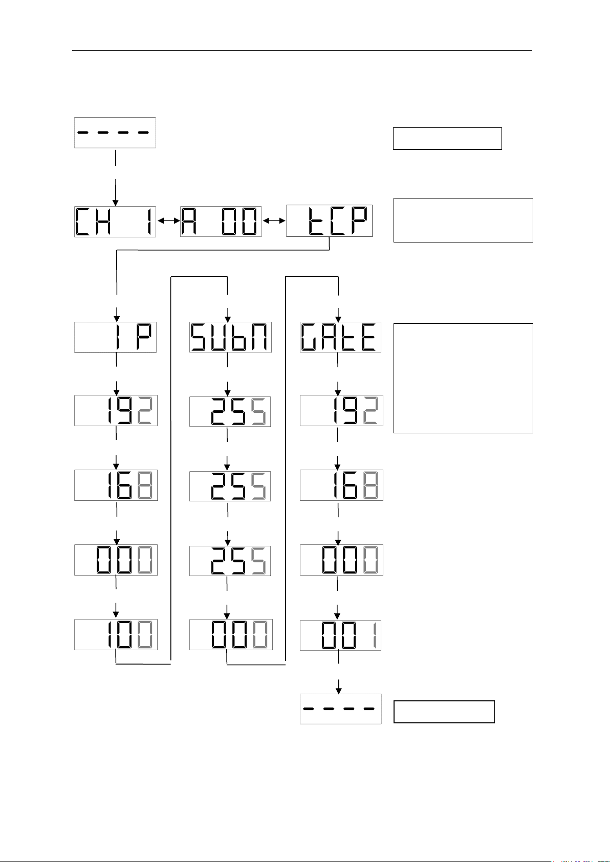
Setting up TCPIP Parameters
Press and hold SET for about one second
Press RANGE Press RANGE
Press SET Press SET Press SET
Press SET Press SET Press SET
Press SET Press SET Press SET
Press SET Press SET Press SET
Press SET Press SET Press SET
Press SET
**REMARK:
- Default IP: 192.168.0.100
- Default Subnet Mask: 255.255.255.0
- Default Gateway: 192.168.0.1
Idle State
Setting for:
- IP Address
- Subnet Mask
- Default Gateway
In the form of:
www.xxx.yyy.zzz
Select “TCP” for IP Address
Setting
Idle State
TMS Lite LC-18-4CH-KP1
12
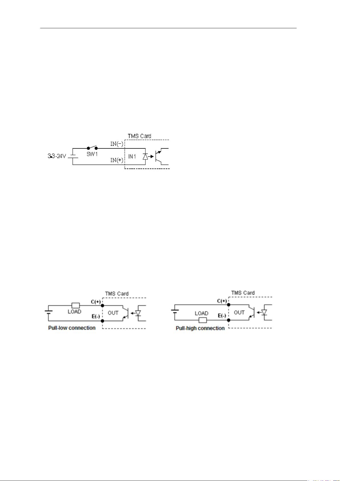
Input Signal
Input signal is used to turn on the lighting under Strobe/Trigger mode.
The lighting output is turned on after a delay time defined by Strobe Delay, while the turn on
duration is defined by Strobe Width.
Acceptable voltage for external input signal is from 3.3-24VDC.
The external trigger signal can be configured as rising edge or falling edge trigger.
Output Signal
The output signal is optional and is used to trigger external devices such as smart camera. The
output signal is only available in Strobe Mode.
The output pulse is triggered after a delay time defined by Output Delay, while the turn on
duration is defined by Output Width.
TMS Lite LC-18-4CH-KP1
13
Drawing Dimension

TMS Lite LC-18-4CH-KP1
14
Communication Protocol
1. Communication Setting
COMPORT
Baud Rate = 115200
Data Bits = 8
Parity = None
Stop Bits = 1
TCPIP
Default IP: 192.168.0.100
Default Subnet Mask: 255.255.255.0
Default Gateway: 192.168.0.1
Port No: 80
USB - HID
Vendor ID = 5A51
Product ID = 0011
TMS Lite LC-18-4CH-KP1
15
2. Command
Message Format (ASCII)
Write
@
W
X
YY
{
ZZZZ
}
Starting
Byte
Board
Address
Channel
No.
Command
Code
Open
Bracket
Data
Close Bracket
(End Byte)
Read
@
W
X
YY
{
}
Starting
Byte
Board
Address
Channel
No.
Command
Code
Open
Bracket
Close Bracket
(End Byte)
Return Message
@
W
X
YY
{
ZZZZ
}
Starting
Byte
Board
Address
Channel
No.
Command
Code
Open
Bracket
Data
Close Bracket
(End Byte)
Starting Byte
Symbol “@” is used as starting byte
Board Address
W = 0
(Fixed Address)
Channel No.
Channel number
X = 1 ~ 4;
Data
Data is set inside a set of Bracket
Max data length = 4 digits
Refer table Command List for No. of byte of data for each command

TMS Lite LC-18-4CH-KP1
16
3. Write
Command List
Command Code (YY)
Command Description
Data
No. of Byte
SM
Set Channel Mode
0 = Constant
1 = Strobe
2 = Trigger
1
SR
Set Current Multiplier
1-10
2
SI
Set Intensity
0 - 255
3
SD
Set Strobe Delay
0 –9999
(99.99ms)
4
SW
Set Strobe Width
0 –9999
(99.99ms)
4
SY
Set Output Delay
0 –9999
(99.99ms)
4
SH
Set Output Width
0 –9999
(99.99ms)
4
ST
Strobe
NONE
0
EE
Save EEPROM
NONE
0
**REMARK:
For Save EEPROM function, use any channel no. for x value, all channels’ parameters will
be saved
Return Message
Controller will send a return message same as the command sent to the controller to indicate
successful sending.
If wrong command or data are sent, a message of {ERR} in the bracket will be returned.

TMS Lite LC-18-4CH-KP1
17
4. Read
Command List
Command Code (YY)
Command Description
Return
Data (ZZZZ)
No. of Byte
RM
Read Channel Mode
0 = Constant
1 = Strobe
2 = Trigger
1
RR
Read Current Multiplier
1-10
2
RI
Read Intensity
0 –255
3
RD
Read Strobe Delay
0 –9999
(99.99ms)
4
RW
Read Strobe Width
0 –9999
(99.99ms)
4
RY
Read Output Delay
0 –9999
(99.99ms)
4
RH
Read Output Width
0 –9999
(99.99ms)
4
RV
Read Version
WXYZ
(W.X.Y.Z)
0
**REMARK:
For Read Version function, use any channel no. for X value

TMS Lite LC-18-4CH-KP1
18
Example
Write
Board Address = 0
1) Set CH1 to constant mode
Tx > @01SM{0}
Rx < @01SM{0} (Success)
2) Set CH1 to strobe mode
Tx > @01SM{1}
Rx < @01SM{1} (Success)
3) Set CH1 Intensity = 90
Tx > @01SI{90}
Rx < @01SI{90} (Success)
4) Set CH1 Strobe Width = 500 (50.0ms)
Tx > @01SW{500}
Rx < @01SW{500} (Success)
5) Strobe CH1
Tx > @01ST{}
Rx < @01ST{} (Success)
6) Save EEPROM parameter
Tx > @01EE{}
Rx < @01EE{} (Success)
Board Address = 1
1) Set CH1 to constant mode
Tx > @11SM{0}
Rx < @11SM{0} (Success)
2) Set CH2 Intensity =200
Tx > @12S2{200}
Rx < @12S2{200} (Success)
3) Set CH1 Strobe Width = 1000 (100.0ms)
Tx > @11SW{1000}
Rx < @11SW{1000} (Success)

TMS Lite LC-18-4CH-KP1
19
Read
1) Read CH1 mode = Constant
Tx > @01RM{}
Rx < @01RM{0} (Success)
2) Read CH1 Current Multiplier = 2
Tx > @01RR{}
Rx < @01RR{02} (Success)
4) Read CH1 Intensity = 150
Tx > @01RI{}
Rx < @01RI{150} (Success)
5) Read CH2 Strobe Delay = 500 (50.0ms)
Tx > @02RD{}
Rx < @02RD{0500} (Success)
6) Read CH2 Strobe Width = 2000 (200.0ms)
Tx > @02RW{}
Rx < @02RW{2000} (Success)
7) Read Board Version
Tx > @01RV{}
Rx < @01RV{1000} (Success)
Wrong Command or Data Sending
Tx > @01SI{500}
Rx < @01SI{ERR}
Tx > @08SC{3}
Rx < @08SC{ERR}
Tx > @1SH{1}
Rx < @1SH{ ERR }
Table of contents
Popular Lighting Equipment manuals by other brands

TACSWAN
TACSWAN FoxFury EXOLANDER 700-XDS-M2P product manual

LUG
LUG INTO R LED Installation instruction

KSR
KSR Navara HBX Installation sheet

Marmitek
Marmitek Glow XSE GU10 quick start guide

Philip Payne
Philip Payne 250DW Series manual

Light Efficient Design
Light Efficient Design LED-8088M Series Instruction & installation manual

Showgear
Showgear VIBE FX Polar Beat manual

NANLITE
NANLITE Forza 500 user manual

Lightolier
Lightolier Lytespan 23S70P3 specification

Saxby Lighting
Saxby Lighting Orion20 instruction manual

Theben
Theben TIMEGUARD LEDBHR25WPIR Installation and operating instructions

Ecco
Ecco ED3766 Series Installation and operation instruction


