ESPAÑOL
- 9 -
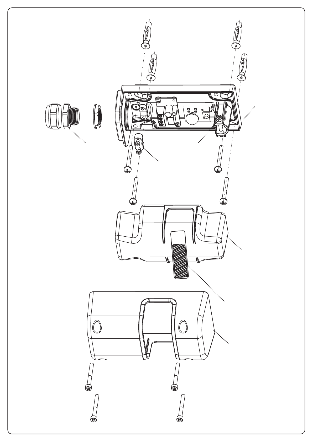
INSTALACIÓN DE PARED (Fig.1)
Para un correcto funcionamiento del sistema es necesario vericar
la planeidad y linealidad de la supercie en los puntos previstos
para la instalación, por lo que DEBE FIJAR EL PROYECTOR DE
FRENTE AL RECEPTOR A LO LARGO DEL MISMO EJE GEOMÉTRICO
Y A LA MISMA ALTURA DE TIERRA.
Dado que es posible orientarlo a 180° sobre el eje horizontal y
30° sobre el eje vertical, el SHIELD-180 también puede utilizarse
donde las supercies de jación impiden una alineación correcta
entre TX y RX.
Para conseguir una instalación correcta siga atentamente las
siguientes instrucciones:
• Denalospuntosprevistosparalainstalación,teniendoen
cuenta que es necesario jar las fotoceldas sobre una supercie
uniforme y plana.
mATENCIÓN: coloque las fotoceldas a modo de evitar
que el receptor RX se encuentre de frente al sol.
• Denaeltrayectodelosconductosparaelpasodeloscables
de alimentación.
• AbraelcontenedordelafotoceldayutilicelabaseApara el
trazo de las perforaciones de jación.
• FijelabaseA
• DesmonteelpasacablesD
• Realicelasconexioneseléctricashaciendopasarelcableporel
pasacables E.
• MonteelpasacablesD
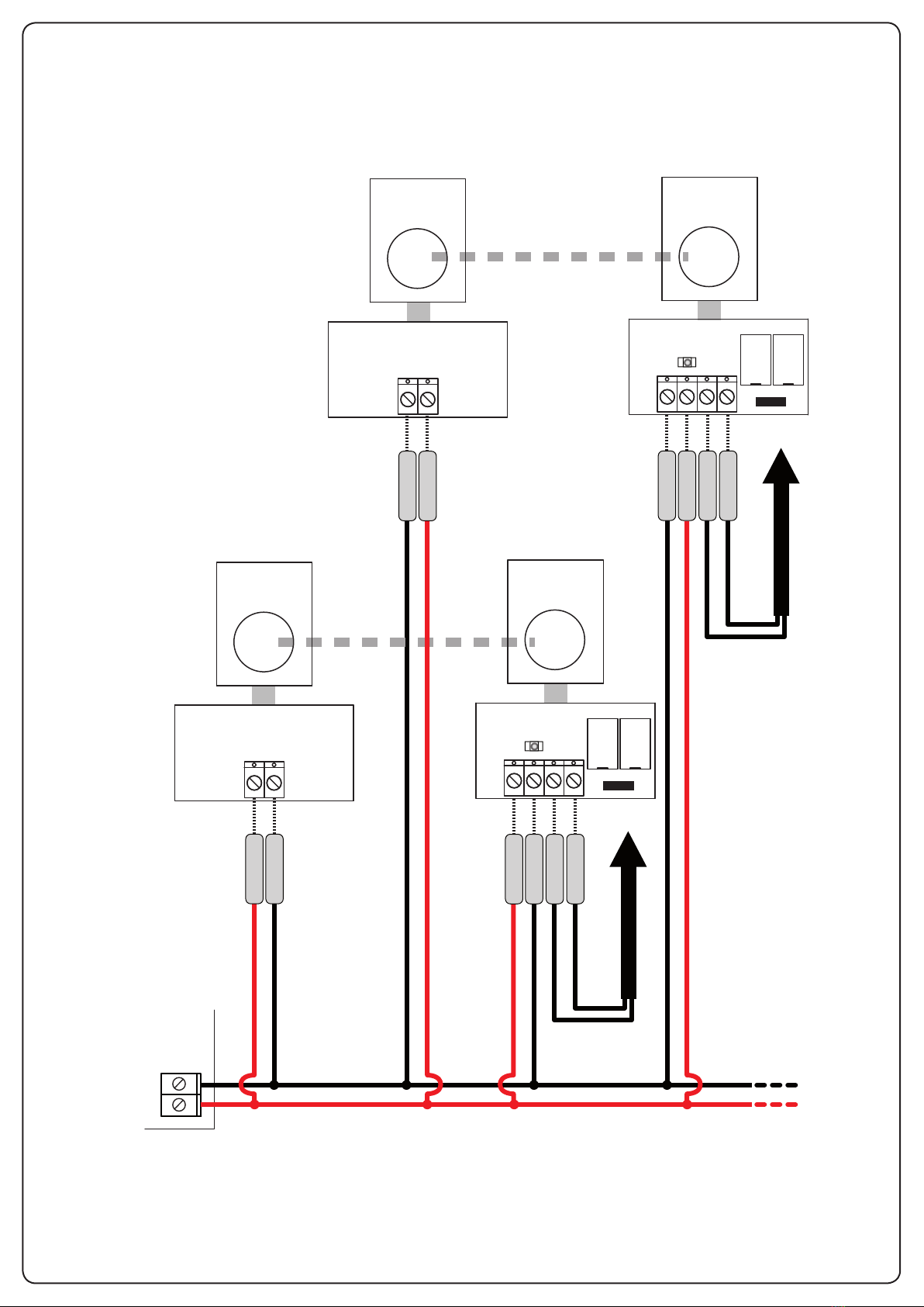
CONEXIONES ELÉCTRICAS
mATENCIÓN: La instalación del cuadro, de los
dispositivos de seguridad y de los accesorios tiene que
hacerse con la alimentación desconectada
La nueva serie de dispositivo se ha implementado con un circuito
de sincronía que permite montar dos pares aún muy próximos sin
que intereran entre sí.
mATENCIÓN: la alimentación de TX y RX debe estar en
fase (es decir, la masa del TX con la masa del RX y los 24
VCA del TX con los 24 VCA del RX).
Funcionamiento sincronizado - conectar como Fig. 4
Alimente con corriente alterna los dos pares de fotoceldas,
invirtiendo la polaridad entre el primero y el segundo par.
Funcionamiento NO sincronizado - conectar como Fig. 5
Alimente con corriente continua los dos pares de fotoceldas e
instale los dos pares en modo inverso uno respecto al otro.
JUMPER (Fig. 3)
JUMPER J1 (RX)
Posición A - salida relé con contacto normalmente cerrado
(DEFAULT)
Posición B - salida relé con contacto normalmente abierto
PUESTA A PUNTO
Concluida la instalación compruebe que el sistema funciona
correctamente:
1. Inspeccione para garantizar que ningún objeto físico se
interponga entre el transmisor y el receptor.
2. Alimente el sistema:
- El diodo luminoso del receptor está apagado: la fotocelda
no está centrada, mecer lentamente la parte móvil hasta
que el diodo luminoso del receptor encienda.
- El diodo luminoso del receptor está encendido: la fotocelda
está centrada, pase al punto 3.
mATENCIÓN: si el led del receptor parpadea, la
alimentación de TX y RX no está en fase.
Comprobar las conexiones eléctricas.
3. Sujete la parte móvil de la fotocélulas ajustando el tornillo M
4. Inserte la cubierta Bsobre las fotoceldas y compruebe el
funcionamiento correcto sin retirar el ltro adhesivo de
atenuación C(el ltro simula condiciones meteorológicas
adversas como lluvia, niebla, etc.)
5. Retire, por lo tanto, el ltro de atenuación.
6. Interrumpa varias veces el haz infrarrojo: el diodo del receptor
se debe apagar y el relé debe conmutar.
7. Introduzca la cubierta de aluminio F y je los 4 tornillos
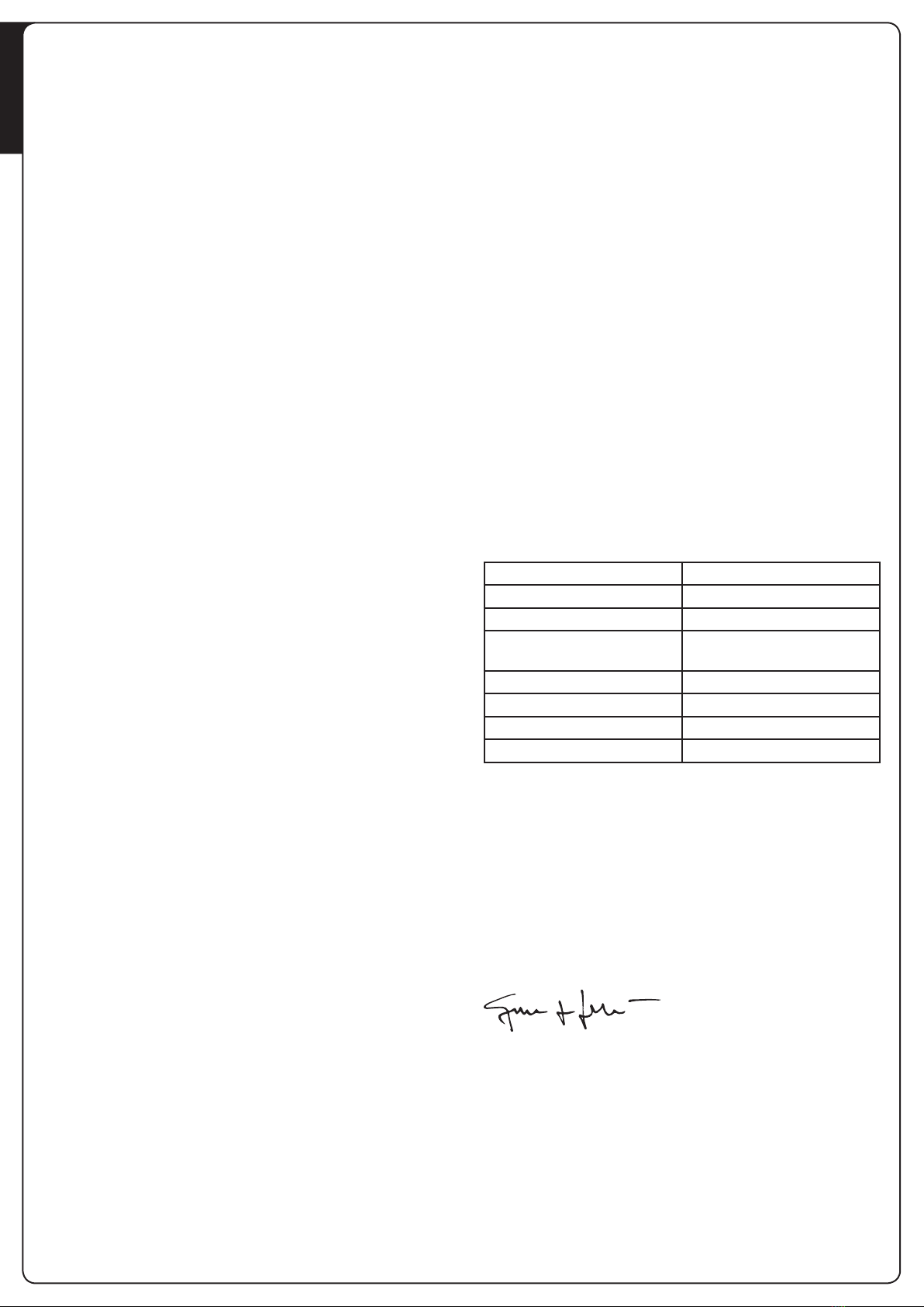
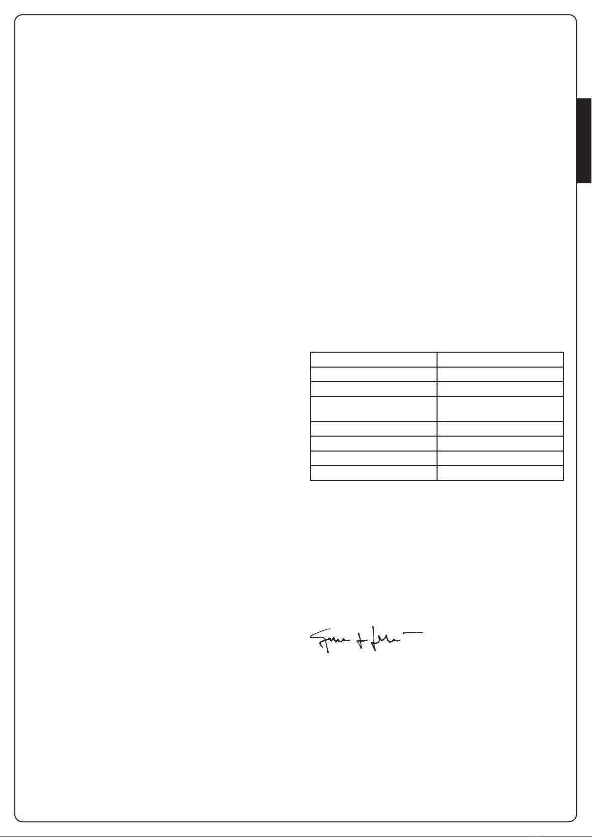
CARACTERÍSTICAS TÉCNICAS
Alcance óptico 20 m
Dimensiones 74x141x55 mm
Alimentación (VIN - GND) 12÷24 Vac / 12÷36 Vdc
Segnale infrarrojo modulado 2 KHz
l= 940 nm
Potencia máxima relé 1A max 30 VDC
Absorción (VIN = 24Vdc) TX 15 mA RX 20 mA
Temperatura de funcion -20° + 60° C
Grado de protección IP55
DECLARACIÓN UE DE CONFORMIDAD
V2 S.p.A. declara que los productos SHIELD-180 cumplen los
requisitos esenciales establecidos por las siguientes directivas:
• 2014/30/UECompatibilidadelectromagnética
• RoHS22011/65/EC
Racconigi, 01/02/2016
El representante legal de V2 S.p.A.
Giuseppe Pezzetto