Toledo OBD II User manual
1
OBDII EOBD &
CAN Code Reader
User Guide
1. Safety precautions and warnings
To prevent personal injury or damage to vehicle and/or the
scan tool, read this instruction manual first and observe
the following safety precautions whenever working on a
vehicle:
1. Always perform testing in a safe working environment
2. Keep clothing, hair, hands, tools, test equipment, etc. away from all
moving or hot engine parts
3. Operate the vehicle in a well ventilated work area
4. Put the vehicle in ‘Park’ for automatic or ‘Neutral’ for manual
transmission and apply parking brake
302200
5. Never leave the vehicle unattended
6. Use extreme caution when working around the ignition coil, distributor
cap, ignition wires and spark plugs. These components create
hazardous voltages when the engine is running
8. Keep a fire extinguisher on hand suitable for petrol/chemical and
electrical fires
9. Don’t connect or disconnect any test equipment while the ignition is on
or the engine is running
10. Keep the scan tool dry, clean, free from oil/water or grease. Use a
mild detergent on a clean cloth to clean the outside of the scan tool
when necessary
1Safety precautions and warnings 1
2General information 2
2.1 On-Board Diagnostics (OBD) II 2
2.2 Diagnostic Trouble Codes (DTCs) 2
2.3 Location of the Data Link Connector (DLC) 2
2.4 OBD II readiness monitors 2
2.5 OBD II monitor readiness status 2
2.6 OBD II definitions 3
2.7 OBD II modes of operation 3
3Using the scan tool 4
3.1 Tool description 4
3.2 Specifications 4
3.3 Navigation characters 4
3.4 Keyboard 4
3.5 Power supply 4
3.6 Tool setup 4
3.7 About 5
3.8 Vehicle coverage 5
4OBDII diagnostics 6
4.1 Read codes 6
4.2 Erase codes 6
4.3 Data stream 7
4.4 View freeze frame 7
4.5 I/M Readiness 8
4.6 Vehicle info 8
4.7 Exiting the OBDII test 8
5I/M Readiness 8
5.1 Ready test mode 8
5.2 Scan tool mode 9
6Product troubleshooting 9
Table of contents Page
2
2.1 On-Board Diagnostics (OBD) II
The first generation of On-Board Diagnostics (called OBD I) was developed
by the California Air Resources Board (ARB) and implemented in 1988
to monitor some of the emission control components on vehicles. As
technology evolved and the desire to improve the On-Board Diagnostic
system increased, a new generation of On-Board Diagnostic system was
developed. This second generation of On-Board Diagnostic regulations is
called “OBD II”. The OBD II system is designed to monitor emission control
systems and key engine components by performing either continuous or
periodic tests of specific components and vehicle conditions. When a fault
is detected, the OBD II system turns on a Malfunction Indicator Lamp (MIL)
on the vehicles instrument panel to alert the driver typically by the phrase
of “Check Engine”. The system will also store important information about
the detected malfunction so that the technician can accurately find and fix
the fault.
Main function of the code reader
1. Read stored Diagnostic Trouble Codes (DTC) when the Malfunction
Indicator Lamp (MIL) turns on
2. Erase and clear fault codes once repair has been performed to turn off
the MIL warning light
3. Readiness Monitor status
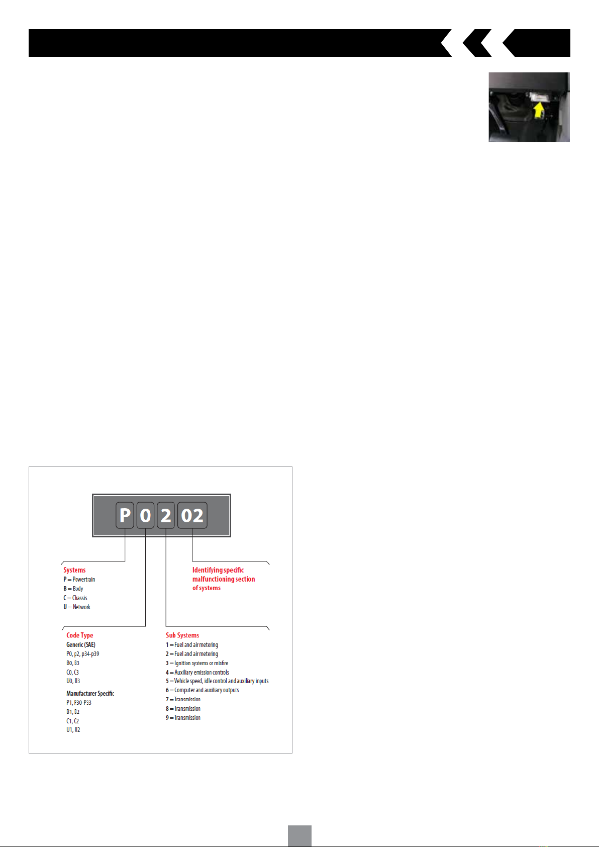
2.2 Diagnostic Trouble Codes (DTCs)
OBD II Diagnostic Trouble Codes are codes that are stored by the on-board
computer diagnostic system in response to a fault found in the vehicle.
These codes identify a particular problem area and are intended to
provide you with a guide as to where a fault might be occurring within
a vehicle. OBD II Diagnostic Trouble Codes consist of a five digit
alphanumeric code. The first character, a letter, identifies which control
system sets the code. The other four characters, all numbers provide
additional information on where the DTC originated and the operating
conditions that caused it to set.
Understanding Diagnostic Trouble Codes (DTC)
2. General information
2.3 Location of the Data Link Connector (DLC)
The DLC (Data Link Connector or Diagnostic Link Connector) is the
standardised 16-cavity connector where diagnostic scan tools interface
with the vehicle’s on-board computer.
2.4 OBD II Readiness Monitors
An important part of a vehicle’s OBD II system is the Readiness Monitors
which are indicators used to find out if all of the emissions components
have been evaluated by the OBD II system. They run periodic tests on
specific systems and components to ensure they are performing within
specifications. There are eleven OBD II Readiness Monitors. Not all
monitors are supported by all vehicles and the exact number of monitors on
any vehicle depends on the manufacturers emissions control strategy.
Continuous Monitors
Some of the vehicle components or systems are continuously tested by
the vehicle’s OBD II system, while others are tested only under specific
vehicle operating conditions. Below are the listed continuous monitored
components
1 Misfire
2 Fuel System
3 Comprehensive Components Monitor (CCM)
Once the vehicle is running, the OBD II system is continuously checking the
above components, monitoring key engine sensors, detecting for engine
misfire, and monitoring fuel demands
Non-Continuous Monitors
Unlike the continuous monitors, many emissions and engine system
components require the vehicle to be operated under specific conditions
before the monitor is ready. Below are the listed non-continuous monitors
1 EGR system
2 O2 sensors
3 Catalyst
4 Evaporative system
5 O2 sensor heater
6 Secondary air
7 Heated catalyst
8 A/C system
2.5 OBD II Monitor Readiness Status
OBD II systems must indicate whether or not the vehicle’s Powertrain
Control Module (PCM) monitor system has completed testing on each
component. Components that have been tested will be reported as “Ready”
or “Complete” meaning they have been tested by the OBD II system. The
purpose of recording readiness status is to allow inspectors to determine if
the vehicle’s OBD II system has tested all the components and/or systems.
The PCM sets a monitor to “Ready” or “Complete” after an appropriate
drive cycle has been performed. The drive cycle that enables a monitor
and sets readiness codes to “Ready” varies for each individual monitor.
Once a monitor is set as “Ready” or “Complete” it will remain in this state.
A number of factors, including erasing of DTC’s with a scan tool
or a disconnected battery, can result in readiness monitors being set to
“Not Ready”. Since the three continuous monitors are constantly
evaluating, they will be reported as “Ready” all of the time. If testing of a
particular supported non-continuous monitor has not been completed, the
monitor status will be reported as “Not Complete” or “Not Ready”.
In order for the OBD monitor system to become ready, the vehicle should
be driven under normal operating conditions. These operating conditions
may include a mix of highway driving and stop and go, city type driving,
and at least one overnight off period. For specific information on getting
your vehicle’s OBD monitor system ready, please refer to your vehicle
manufacturers workshop manual.
Fig.1
The DLC is usually located on the lower section
of the dashboard on the drivers side, under
or around the foot well even behind a trim on
most vehicles (Fig.1). If you are unable to locate
the Data Link Connector under the dashboard
always refer to the manufactures workshop
manual for location.

3
2.6 OBD II Definitions
Powertrain Control Module (PCM)
OBDII terminology for the on-board computer that controls engine and
drivetrain.
Malfunction Indicator Light (MIL)
Malfunction Indicator Light (Check Engine) is a term used for the light on
the instrument panel. It is to alert the driver and/or the repair technician
that there is a fault with one or more of vehicle’s systems and may cause
emissions to exceed its limitation. If the MIL illuminates with a steady
light, it indicates that a fault has been detected and the vehicle should be
repaired as soon as possible. Under certain conditions, the dashboard light
will blink or flash. This indicates a severe problem and flashing is intended
to discourage vehicle operation. The vehicle on-board diagnostic system
cannot turn the MIL off until necessary repairs are completed or the
condition no longer exists.
Diagnostic Trouble Codes (DTC)
Diagnostic Trouble Codes that identify which section of the emission
control system has malfunctioned.
Enabling Criteria
Also called Enabling Conditions. They are the vehicle specific events or
conditions that must occur within the engine before the various monitors
will set or run. Some monitors require the vehicle to follow a prescribed
“drive cycle” routine as part of the enabling criteria. Drive cycles vary
among vehicles and for each monitor in any particular vehicle.
OBD II Drive Cycle
A specific mode of vehicle operation that provides conditions required
to set all the readiness monitors applicable to the vehicle to the “ready”
condition. The purpose of completing an OBD II drive cycle is to force the
vehicle to run its on-board diagnostics. Some form of a drive cycle needs
to be performed after DTC’s have been erased from the PCM’s memory
or after the battery has been disconnected. Running through a vehicle’s
complete drive cycle will set the readiness monitors so that future faults
can be detected. Drive cycles vary depending on the vehicle and the
monitor that needs to be reset. For vehicle specific drive cycle, refer to your
vehicle manufacturers workshop manual.
Freeze Frame Data
When an emission related fault occurs, the OBD II system not only sets a
code but also records a snapshot of the vehicle operating parameters to
help in identifying the problem. This set of values is referred to as Freeze
Frame Data and may include important engine parameters such as engine
RPM, vehicle speed, air flow, engine load, fuel pressure, fuel trim value,
engine coolant temperature, ignition timing advance or closed loop status.
Descriptions of the modes:
Mode $01 Identifies the Powertrain information and shows current data
available to the scan tool. This data includes: DTC’s set,
status of on-board tests and vehicle data such as engine
RPM, temperatures, ignition advance, speed, air flow rates,
and closed loop status for fuel system.
Mode $02 Displays Freeze Frame data. Same data as in mode 1, but it
was captured and stored when a malfunction occurred and
a DTC was set. Some of the on-board diagnostics parameter
IDs (PIDs) for mode one are not implemented in this mode.
Mode $03 Displays the type of powertrain or emission related DTCs
stored by a 5 digit code identifying the faults. There may be
more than one response message if there are more trouble
codes than will fit in the data bytes of the response message
or if there are more than one ECU computer responding.
Mode $04 Used to clear DTCs and freeze frame data. This clears all
diagnostic trouble codes that may be set including freeze
frame data and readiness monitors.
Mode $05 Oxygen Sensor Test Results. This mode displays the oxygen
sensor monitor screen and the test results gathered by the
oxygen sensor.
Mode $06 Non-continuously monitored systems test results. There are
typically a minimum value, a maximum value, and a current
value for each non-continuous monitor. This data is optional,
and it is defined by a given vehicle make if it’s used
Mode $07 Request for DTCs (pending) from continuously monitored
systems after a single driving cycle has been performed
to determine if repair has fixed a problem. This is used by
service technicians to verify repair was performed properly
and after clearing diagnostic trouble codes.
Mode $08 This special control mode requests control of the on-
board system to test or component bi-directionally (where
applicable). This mode is manufacturer specific.
Mode $09 Reports vehicle information. This information includes vehicle
VIN number and calibration information stored in the vehicle
ECU’s.
Mode $10 Requests emission related diagnostic trouble codes with
permanent status. This mode is required for all emissions
related DTC’s. The presence of permanent DTC’s at an
inspection without the MIL illuminated is an indication
that a proper repair was not verified by the on-board
monitoring system.
Available 02 sensor tests
$01 Rich-to-Lean O2 sensor threshold voltage
$02 Lean-to-Rich O2 sensor threshold voltage
$03 Low sensor voltage threshold for switch time measurement
$04 High sensor voltage threshold for switch time measurement
$05 Rich-to-Lean switch time in ms
$06 Lean-to Rich switch time in ms
$07 Minimum voltage for test
$08 Maximum voltage for test
$09 Time between voltage transitions in ms
2.7 OBD II Modes of Operation
Basic introduction to the OBD II communication protocol
Mode byte the first byte in the stream is the mode number. There are 9
modes for diagnostic request, the first byte is from 1 to 9. The first byte in
the response data bytes is this same number plus 64.
For example, a mode 1 request would have the first data byte = 1 and the
response would have the first data byte = 65
2. General information cont.

4
3.1 Scan tool description
3. Using the scan tool
3.2 Specifications
Screen 2.0” TFT colour display (220 x 176 dpi)
External Power 8.0 to 16.0 volts, provided via vehicle battery
Operating temperature 0 to 60 °C (32 to 140 °F)
Storage temperature -20 to 70 °C (-4 to 158 °F)
Dimensions (mm) Length 124 x Width:72 x Height 18
GW 0.21kg
3.3 Navigation Characters
Characters used to help navigate the scan tool
#- Identifies the control module number from which data is retrieved
Pd - Identifies a pending DTC when viewing DTC’s
3.4 Keypad
Use only a mild non-abrasive detergent and a soft cotton cloth when
cleaning keypad and screen. Do not use solvents such as alcohol or
automotive degreasers. Do not soak the keypad
3.5 Power supply
The power source from the vehicle will supply the scan tool via the data link
connector
3.6 Tool Setup
The scan tool allows you to make the following personalised settings
1 Language - Select the preferred language
2 Unit of measure - Set the unit of measure to Metric or Imperial
3 Key Beep Set - Turns on/off key-press beep
4 Status Beep Set - Turns on/off the I/M Readiness Status beep
5 Fn Key Set - Set the One-Click-Quick Function Key including usual
Datastream, All Datastream, I/M readiness status and read code
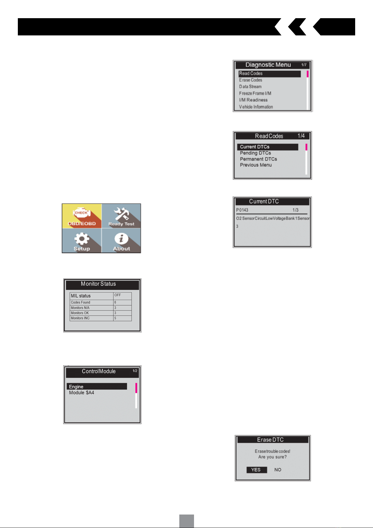
Main Menu
When the scan tool is turned on, it will display the main screen
Tool Setup Menu
1 Language
NOTE: Language is set in English by default
From the Tool Setup menu scroll through and highlight Language and press
the ‘ENTER’ key
Scroll down the Language menu and highlight the preferred language
Press the ‘ENTER’ key to save your selection and return the to
previous screen
2 Unit of Measure
NOTE: Unit of measure is set to Metric by default
From the Tool Setup menu scroll through and highlight Unit of Measure and
press the ‘ENTER’ key
Highlight to select Metric or English as preferred unit
Press the ‘ENTER’ key to save your selection and return to the previous
screen
1 OBD II CONNECTOR - Connects the scan tool to the vehicle’s Data Link
Connector (DLC)
2 LCD DISPLAY - Indicates test results
3 GREEN LED - Indicates that engine systems are running normally
4 YELLOW LED - Indicates there is a possible fault. A “Pending” DTC is
present and/or some of the vehicle’s emission monitors have not run their
diagnostic testing
5 RED LED - Indicates there is a fault in one or more of the vehicle’s
systems. The red LED is also used to show that DTCs are present
6 Fn (one-click function) key - Shortcut for 4 quick function including I/M
readiness status, read code, usual Datastream and all Datastream
7 ENTER/EXIT KEY - Confirms a selection (or action) from a menu or return
to previous menu
8 SCROLL KEY - Scrolls through menu items
2 LCD DISPLAY
5 RED LED
8 SCROLL KEY
1 OBD II
CONNECTOR
3 GREEN LED
7 ENTER/EXIT KEY
6 Fn
4 YELLOW LED

5
3 Key Beep Set
NOTE: Key beep set is set to ON by default
From the Tool Setup menu scroll through and highlight Key Beep Set and
press the ‘ENTER’ key
Highlight to select Beep ON or Beep OFF to turn on/off the beep
Press the ‘ENTER’ key to save your selection and return to the previous
screen
4 Status Beep Set
This function allows you to turn on/off the build-in speaker for the LED’s in
diagnostic testing. Different audio tone corresponds to different LED lights.
From the Tool Setup menu scroll through and highlight Status Beep Set and
press the ‘ENTER’ key
Highlight to select Beep ON or Beep OFF to turn on/off the beep
Press the ‘ENTER’ key to save your selection and return to the previous
screen
5 Fn Key Set
From the Tool Setup menu scroll through and highlight FN Key Set
and press the ‘ENTER’ key
This menu will allow you to configure the ‘Fn’ key setting for
one-click function
Scroll through the options and highlight the selected command
Press the ‘ENTER’ key to save your selection and return to the previous
screen
Usual Datastream Mode
Once the vehicle’s monitors run and complete their diagnosis and testing,
the scan tool will recommend relevant Datastream as important data for
the user as reference.
3. Using the scan tool cont.
All Datastream Mode
Once the vehicle’s monitors run and completed their diagnosis and testing.
The scan tool will check all data stream and return to the monitor’s
status screen
I/M Readiness Mode
This Mode is the default work mode. Once the vehicle’s monitors have run
and completed their diagnosis and testing, the scan tool will be ready to
use for OBDII diagnostic procedures
Read Codes Mode
Read Codes Mode is the basic work mode. Once the vehicle’s monitors
have run and completed their diagnosis and testing, the scan tool will read
the trouble codes
To exit the Setup menu
Scroll and highlight to the ‘Previous Menu’ line and press the ‘ENTER’ key
and return to the main screen
3.7 About
This menu will allow you to view the serial number and software version on
the scanner
From the Main Menu scroll through and highlight About and press the
‘ENTER’ key
The Tool Information screen will appear
Press the ‘ENTER/Exit’ key to return to the main menu
3.8 Vehicle Coverage
The scan tool OBD II/EOBD scanner is specially designed to work with all
OBD II compliant vehicles, including those equipped with Control Area
Network (CAN) system. A small number of 1994 and 1995 model year petrol
engine vehicles are OBD II compliant. To verify check the Vehicle Emissions
Control Information Label (VECI) which may be located in the engine bay,
underside of the bonnet or by the radiator support panel on most vehicles.
If the vehicle is OBD II compliant the label will indicate “OBDII Certified”.
All OBD II compliant vehicles must have a “common” sixteen-pin Data Link
Connector (DLC) located inside the vehicle under the dash board.
6
When more than one vehicle control module is detected by the scan tool,
you will be prompted to select the module where the result would be retrieved
from. The most common modules are the Power train Control Module (PCM)
and Transmission Control Module (TCM)
CAUTION: Do not connect or disconnect any test equipment with ignition ON
or engine running
How to connect to vehicle
1 Switch the ignition ‘OFF’
2 Locate the vehicle’s Data link Connector (DLC) plug
3 Securely plug the OBD II cable into the vehicle
4 Switch the ignition ‘ON’ (Engine can be ‘OFF’ or ‘RUNNING’)
NOTE: It is recommended to have the engine ‘OFF’ while scanning. This
avoids the engine from getting too hot for further diagnosis and testing and
also reduce the build up of exhaust fumes if working in a confined area.
5 Scroll through and select Diagnostics in the main screen and press the
‘Enter’ key
A sequence of messages displaying the OBDII protocols will be observed on
the display until the vehicle protocol is detected
If the scan tool fails to communicate with the vehicle’s ECU more than
three times, a “LINKING ERROR!” message will be displayed
In this event, verify that the ignition is switched ON
Check if the scan tool’s OBD II connector is securely connected to the
vehicles DLC
6 Wait a few seconds to view a summary of the system status (MIL status,
DTC counts, Monitor status)
7 If more than one module is detected, you can select the module
to be tested
Scroll through and highlight the module and press the ‘Enter’ key
4.1 Read Codes
Stored codes will display as ‘hard codes’ or ‘permanent codes’. These codes
will cause the control module to illuminate the vehicles Malfunction Indicator
Light (MIL) when emission related faults occur
Pending codes will display as ‘maturing codes’ or ‘continues monitor codes’.
They indicate faults that the control module has detected during the current
or last driving cycle but are not considered serious. Pending Codes will
illuminate the Malfunction Indicator Lamp (MIL). If the fault does not occur
within a certain number of warm-up cycles, the code clears from memory.
4. OBD II Diagnostics
1. Highlight ‘Read Codes’ and press the ‘Enter’ key in the Diagnostic Menu. If
there are some codes, the screen will display the codes as shown below:
2. Scroll through to select Current DTCs or Pending DTCs from the read codes
menu and press the ‘Enter’ key
3. View DTC and their definitions on screen. Press the ‘ENTER’ key to
return to previous screen
If there are no DTCs it will display “No (pending) codes are stored in the
module!” Wait a few seconds or press the ‘ENTER’ key to return to the
previous menu
NOTE: Permanent Codes function is available for merely vehicles
supporting the CAN protocols
The control module number, sequence of the DTCs total number of codes
detected and type of codes (Generic or Manufacturer specific, Stored or
Pending codes) will be observed on the upper right hand corner of the
display
4. If more than one DTC is found, scroll through to view all other codes
5. Select previous menu from the read codes screen and press the ‘Enter’
key to return to previous menu
4.2 Erase Codes
CAUTION: Erasing the Diagnostic Trouble Codes (DTC) may not only erase
the codes from the vehicle’s ECU, but also the “Freeze Frame” data and
manufacturer specific enhanced data. Also the I/M Readiness Monitor
Status for all vehicle monitors is reset to Not Ready or Not Complete status.
Do not erase the codes before the fault has been inspected or repaired.
NOTE: Erasing codes does not ensure that the DTC in ECU have been
eliminated completely. As long as there is a fault with the vehicle, the DTC
will keep appearing.
This function is to be performed with the ignition ‘ON’ and the engine ‘OFF’.
Do not start the engine.
1. Scroll through to highlight ‘Erase Codes’ and press the ‘Enter’ key
2. A warning message will appear to confirm your action
NOTE: If ‘NO’ is selected. A message of ‘Command Cancelled!’ will be
displayed. Wait for a few seconds and press any key to return to menu

7
4. OBD II Diagnostics cont.
4.3 Data Stream
The View Data function allows real time view of the on-board diagnostics
Parameter IDs (PID) data of vehicle’s computer module(s)
Depending on how many ECUs and sensors the vehicle is fitted with, it will
display more than one live data if available
1 Scroll through and highlight ‘Data Stream’ from the diagnostics menu
and press the ‘Enter’ key
If no freeze frame data is available a message “No Data Stream!’
wil appear
2 Wait a few seconds while the scan tool validates the PID MAP
3 Once it has finished retrieving information, scroll through to view
available data
4 Press the ‘Enter’ key to return to previous menu
4.4 View Freeze Frame Data
The Freeze Frame Data allows you to view the vehicle’s operating parameters
at the moment a DTC is detected. For example, the parameters may include
engine speed (RPM), engine coolant temperature (ECT), or vehicle speed
sensor (VSS) etc. This information will assist you by allowing the parameters
to be duplicated for diagnostic and repair purposes.
1 Select ‘View Freeze Frame’ from the diagnostic menu and press the
‘Enter’ key
2 Wait until the scan tool validates the PID MAP
3 Once it has finished retrieving information, scroll through to view
available data
A message will appear ‘No Freeze Frame Data Stored!’ if no freeze frame
data is available
4 Press the ‘Enter’ key to return to previous menu
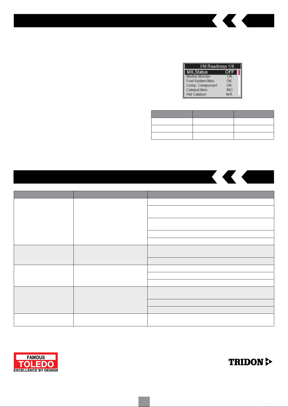
4.5 I/M Readiness
I/M Readiness function is used to self test the operation of the vehicles
emission control system
CAUTION: Erasing the trouble codes also clears the readiness status for the
individual emission system readiness tests. In order to reset these monitors,
the vehicle must be driven through a complete drive cycle with no trouble
codes stored in the memory. Times for reset vary depending on vehicle.
Some later model vehicles may support two types of I/M Readiness tests:
A) Since DTCs Cleared - Indicates status of the monitors since the DTCs
are erased
B) This Drive Cycle - Indicates status of monitors since the beginning of the
current drive cycle
An I/M readiness status result of “NO” does not necessarily indicate that
the vehicle being tested will fail. One or more monitors with the status “Not
Ready” will be able to pass the emissions inspection.
OK - Indicates that a particular monitor being checked has completed its
diagnostic testing
INC - Indicates that a particular monitor being checked has not completed
its diagnostic testing
N/A - The monitor is not supported on that vehicle
1 Scroll through and highlight the I/M Readiness from diagnostic menu
and press ‘Enter’ key
2 Wait until the scan tool validates the PID MAP
3 If the vehicle supports both types of tests, both options will be available
to select
4 Scroll through to view the status of the MIL light (“ON” or “OFF) and the
following monitors:
Misfire monitor - Misfire monitor
Fuel System Mon - Fuel System Monitor
Comp. Component - Comprehensive Components
Monitor Catalyst Mon - Catalyst Monitor
Htd Catalyst - Heated Catalyst Monitor
EVAP System Mon - Evaporative System Monitor
Sec Air System - Secondary Air Monitor
A/C Refrig Mon - A/C system Monitor
Oxygen Sens Mon - O2 Sensors Monitor
Oxygen Sens Htr - O2 Sensor Heater Monitor
EGR System Mon - EGR System Monitor
5 If the vehicle supports readiness test of “This Drive Cycle” the following
screen will be displayed:
3. Press the ‘Enter’ key to confirm
A confirmation message will appear as ‘Erase Done!’
If erasing codes is unsuccessful a message ‘Erase Failure Turn Key on with
Engine Off!’ will appear

8
5. I/M Readiness
There are two modes to show I/M readiness monitor status. You can
configure work modes in the Setup menu.
5.1 Ready Test Mode
Scan Tool Mode is the default work mode. After the vehicle’s monitors have
run and completed their diagnosis and testing, the scan tool will turn to
OBDII diagnostic procedures.
NOTE: Only in this mode can you perform the OBDII diagnostics
The green, yellow and red LEDs provide a quick way to help you determine
if a vehicle is ready for an Emission Test.
The LED and audio tone indications are as interpreted below:
LED Interpretation
1 GREEN LED - Indicates that engine systems are “OK” and operating
normally
The number of monitors supported by the vehicle which have run and
performed their self-diagnostic testing is in the allowed limit. The MIL is
off and there are no stored and pending DTCs. The vehicle is ready for an
Emissions Test.
2 YELLOW LED - Indicates there are three or more possible conditions to
cause the yellow LED to illuminate and with the MIL light off
If the yellow light is illuminated, there is possibly a “Stored” or “Pending”
Diagnostic Trouble Code that has been detected
3 RED LED - Indicates there is a problem with one or more of the vehicle’s
system.
A vehicle displaying a red LED is definitely not ready for an emissions
test. The red LED is also an indication that there are DTCs present. The
MIL lamp on the vehicle’s instrument panel will light steady. The problem
that is causing the red LED to light must be repaired before an Emissions
Test can be performed. It is also suggested that the vehicle be inspected/
repaired before driving the vehicle further.
Audio Tone Interpretation
The audio tone could be configured according to the I/M Readiness Status.
This function is invaluable when working in bright areas where LED
illumination alone is not sufficient.
It is recommended to set the audio tone to Beep ON. For detailed setup
information, please refer to Status Beep Set in 3.7 System Setup.
NOTE: The following audio tone description only works in Scan Tool mode.
Different audio tone with different LED lights will indicates different I/M
Readiness Status.
5.2 Scan Tool Mode
After the vehicle’s monitors have run and completed their diagnosis and
testing, the scan tool will return to the previous screen. This mode is only
used to check the emission-related monitors’ status
NOTE: This function reads off the real time data of emission-related
monitoring systems readiness status every two minutes. Once the scan
tool has finished other operations, for example, clearing trouble codes, and
the real time data been changed, the I/M Readiness Status indication will
be changed accordingly. In order to reset these monitors, the vehicle must
be driven through a complete drive cycle. Times for reset vary depending
on vehicle.
Repairs to the emissions control systems of a 1996 or newer vehicle cause
the vehicle’s computer (ECU) memory to be cleared. The vehicle must go
through a drive cycle to allow the ECU to perform a series of tests to ensure
that the repair was successful, and before a state mandated emissions test
can be conducted.
In the Ready Test Mode it is possible to check the I/M Readiness status to
determine whether an OBD II vehicle is ready for an emission test.
To enter this mode simply press the One-Click (Fn) Key at any time if the
One-Click function key is set to I/M readiness. Or while the scan tool in
Ready Test Mode, select Diagnostics in the main screen.
If the scan tool is at idle it will show the result immediately. If it is busy it
will wait till the current procedure is finished. After viewing the status press
One-Click (Fn) Key or the ‘ENTER’ key to exit. This will take a few seconds.
4. OBD II Diagnostics cont.
4.6 Vehicle Information
The vehicle information feature enables you to retrieve the Vehicle
Identification Number (VIN), Calibration ID Number (CIN), Calibration
Verification Number (CVN) and In-use Performance Tracking on 2000 and
newer vehicles that support Mode 9
1 Select vehicle info and press the ‘Enter’ key
A message will appear ‘Turn key on with engine off! Press any key
to con.’
NOTE: If the vehicle does not support this mode, a warning message will
appear that the mode is not supported
2 If it is not supported, scroll through and select an available option and
press the ‘Enter’ key
3 View retrieved vehicle information
4.7 Exiting the OBDII Test
1 Scroll through and highlight ‘Previous Menu’ and press the ‘Enter’ key
to exit
2 A confirmation message will appear. Press the ‘Enter’ key to exit.
9
Problem Possible cause Solution
Vehicle linking error A communication error occurs if the scan
tool fails to communicate with the vehicle’s
ECU (Engine Control Unit)
Ensure ignition is switched on
Check the scan tools OBD II connector is securely connected to the vehicles
DLC
Switch the ignition off and wait 30 seconds. Switch the ignition back on
and continue testing
Verify the ECU/Control module of the vehicle is not defective
Check if the DLC pins and terminals for damage. Clean if necessary
Operating Error Scan tool freezes or slow to respond Reset the scan tool. Switch the ignition off and wait 30 seconds. Switch
the ignition back on and continue testing
Check if the DLC pins and terminals for damage. Clean if necessary
Scan tool not turning on No power supply to scan tool Ensure ignition is switched on
Vehicle battery voltage at least 8.0 volts
Verify the control module is not defective
LED indicator not working Poor connection Check the scan tools OBD II connector is securely connected to the vehicles
DLC
Ensure ignition is switched on
Run the LED test in the system setup menu
Diagnostic function inoperative Mode selection The scanner maybe in ready test mode. In the system setup menu select
‘Scan Tool Mode’
6. Troubleshooting
302200 MAN © Copyright TRIDON AUSTRALIA PTY. LTD. 2020
A.C.N. 001 398 698 Reproduction of this manual in part or full is not permitted without written approval. Illustrations in this manual are for identification purposes only and there may be slight variations
between the illustration and actual product. Whilst every effort has been made to ensure that the information contained in this catalogue is accurate at the time of printing, TRIDON AUSTRALIA PTY LTD
will not accept responsibility should any inaccuracies be contained herein.
TOLEDO IS A REGISTERED
TRIDON BRAND
5. I/M Readiness cont.
LED Interpretation
In this mode only the GREEN, RED LEDs and audio tone provides an easy
way to check if emission-related monitoring systems complete their self-
diagnostic testing
1 GREEN LED - Indicates that engine systems are “OK” and operating
normally
The number of monitors supported by the vehicle which have run and
performed their self-diagnostic testing is in the allowed limit
2 RED LED - Indicates that the number of monitors supported by the
vehicle which have run and performed their self-diagnostic testing is out
of the allowed limit
Audio Tone Interpretation
The audio tone could be configured according to the I/M Readiness Status.
This function is invaluable when working in bright areas where LED
illumination alone is not sufficient.
OK - Indicates that a particular monitor being checked has completed its
diagnostic testing
INC - Indicates that a particular monitor being checked has not completed
its diagnostic testing
N/A - The monitor is not supported on the vehicle
LED and Audio tone correspondence
LED Light Audio Tone Beep Interval
Green LED Beef off
Yellow LED Two short beeps 0.5 seconds
Red LED Two short beeps 0.5 seconds
This manual suits for next models
1
Table of contents


