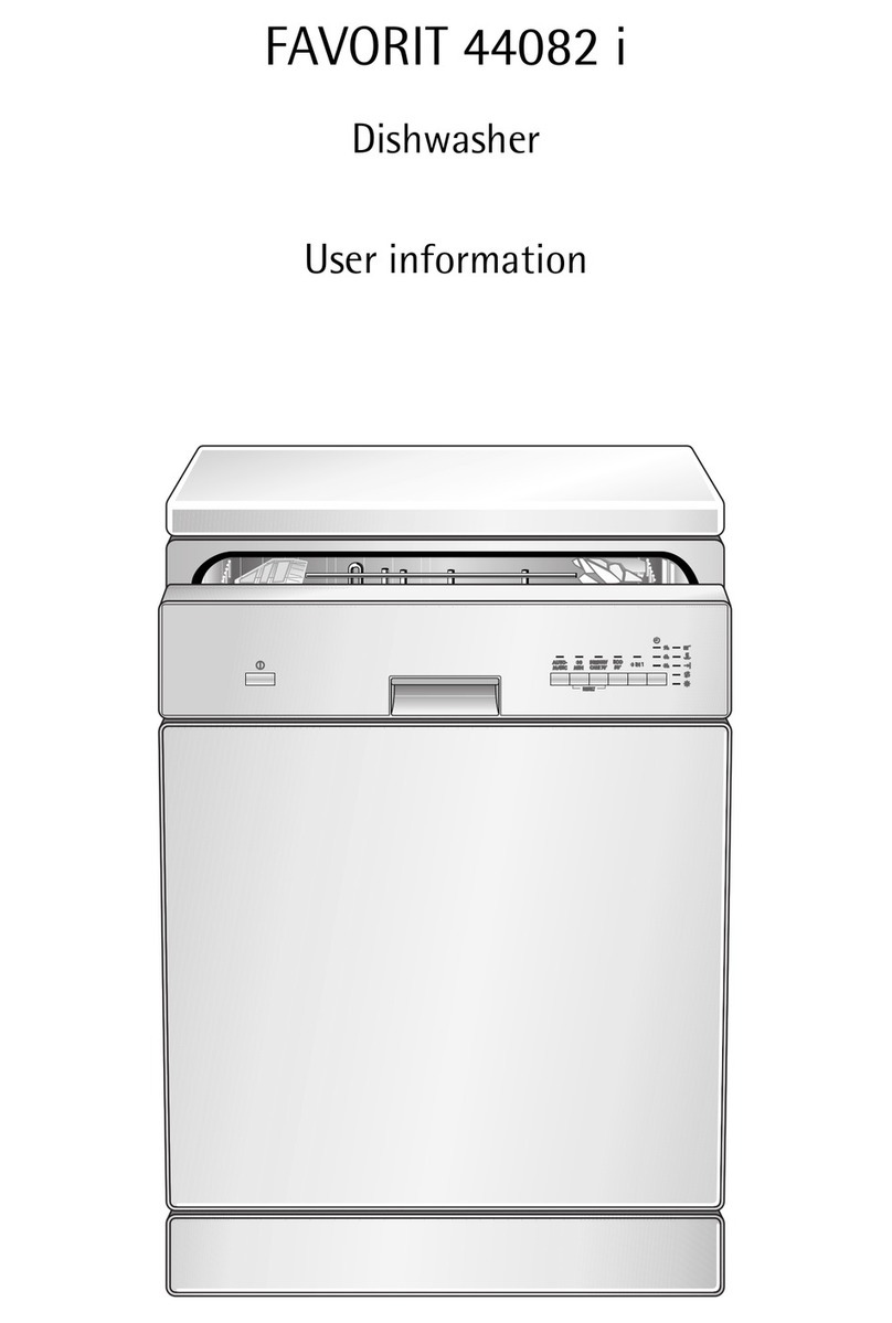
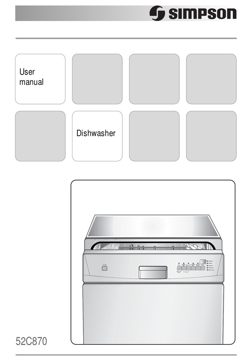
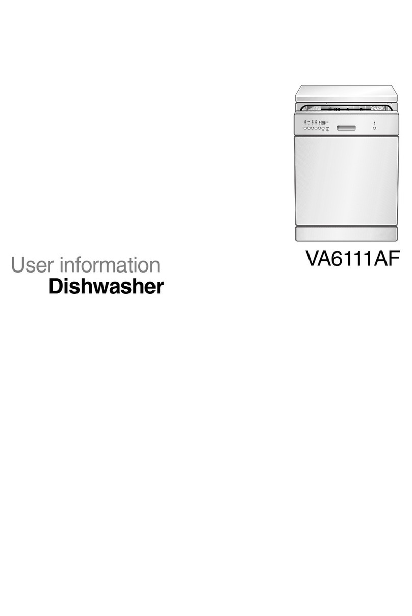
TONG YANG MAGIC DWA-2033 User manual

BEFORE SERVICING THE APPLIANCE,
READ THIS A/S MANUAL
CONTENTS
1. APPLIANCE SPECIFICATIONS - 2
2. FUNCTIONS OF THE BUTTON - 3
3. NAME OF PARTS - 4
4. ELECTRIC PART SPECIFICATION - 5~8
5. CIRCUIT DIAGRAM - 9
- 10~15
7. TROUBLE SHOOTING GUIDE - 16~27
8. TECHNICAL GUIDE - 28
9. DISASSEMBLING & ASSEMBLING - 29~35
10. WATER SOFTENER - 36
- 37~46
October-2006
6. SELF TEST PROGRAM AND ERROR
CHECK LIST
DISH WASHER
A/S MANUAL
DWA-2033
11. EXPLODED VIEW & PART LIST

Remark
Eco. Course
Eco. Course
(with regeneration)
Eco. Course
KOR-3301H
FLOW METER
Temperature perception method
Washing method
2200W
2000W
150W
Installation method
Overall Dimension(mm)
Weight
The 1 course consumption
of power
Inlet water temperature
Total
Heater
Circulation pump
Drain pump
Power
Consumption
Item
Type
Model
Capacity
1.APPLIANCE SPECIFICATIONS
Condensing force air ventilation dry type
Float s/w
Room temperature 2 times/
60℃ Heating 1 time
Thermistor(40,45,50,60,65,70,75,80℃)
0.86kWh
Contents
Power sourse
0 ~ 70℃
Fully Automatic Dishwasher
598(W)*596(D)*840(H)
10g
Quadruple filter
30W
FREE STANDING
0.2 ~ 8 ㎏f/㎠(bar)
12 place setting
47kg
AC 230V, 50Hz
Detergent amount
Filter
Safety
Rotary jet type
Over flow
Over heating
Drying method
Rinsing method
Thermistor, Thermo fuse, HPS
Fan motor 12W
Required water pressure
Water consumption
Water perception method
The 1 course consumption
of water 15ℓ
3.4 ±0.4ℓ

2.FUNCTIONS OF THE BUTTON

3.NAME OF PARTS

■ Power consumption : 2000W
■ Rated voltage: AC 220V/230V, 60Hz/50Hz
In case of the Fan Motor's trouble :
- At the drying cycle, the noise occurred.
After the dishwasher was chilled enough,
measuring the coil resistance in normal temp.
■ Coil resistance: 24.7Ω~28Ω
4-3. Heater
■ Coil resistance: 163Ω±9Ω
■ Power consumption: 30W
■ Rated voltage/frequency: AC 220V-240V, 50Hz.
4. ELECTRIC PART SPECIFICATION
4-1. Water Circulation Pump
■ Model: CS-0290LY
■ Rated voltage/frequency: AC 230V, 50Hz.
■ Power consumption: 144 ± 15% W
■ Coil resistance:
black-red(SUB) :104.2Ω±5%
■ Rated voltage/frequency : AC 230V, 50Hz
■ Model: B20-6
4-4. Dry Fan ASS'Y
■ Power consumption : 12W
black-violet(MAIN):74.5Ω±5%
■ Model: 1TYM00402
☞ A method of confirming trouble
- The impeller was not rotated.
Therefore the wet vapor does not exhaust,
and dishes cannot be drying.
4-2. Drain Pump
M~
4㎌
450VAC
black
violet
red A
red B

4-5. THERMISTOR
# DATA TABLE OF COIL RESISTANCE
temp coil
resistance
Voltage
division
Value[V]
5 124.2 4.3065
20 60.96 3.7648
30 39.31 3.3139
40 26 2.8261
50 17.6 2.3404
60 12.16 1.8905
70 8.552 1.4976
80 6.112 1.1703
: AC 220V/230V, 60Hz/50Hz
■ Type: N61 TYPE
4-7. INLET VALVE ASS'Y
■ Manufacturer: SAMJU FUSE
■ Rated voltage : 250V 3A
4-6. FUSE
☞A method of confirming trouble : After the dishwasher
was chilled enough, measuring the coil resistance of
thermistor on normal temp.
■ Rated voltage/frequency
■ Water pressure: 0.2 ~8 ㎏/㎠(0.2 ~8 bar)

■ Rated voltage : 230V 16A
☞ A method of confirming trouble
:SEE THE TROUBLE SHOOTING GUIDE
☞ A method of confirming trouble
:SEE THE TROUBLE SHOOTING GUIDE
4-11. DISPENSER
■ Model:549
■ Power consumption:10W
■ Rinse capacity:140mℓ
■ Operating time: 1min / Return time: 5min
4-9. DISPLAY PCB ASS'Y
4-8.LATCH ASS'Y
■ A point of contact : NORMAL CLOSE
■ Detegent capacity:40g(15g+25g)
4-10. MAIN PCB ASS'Y
Inlet v/v relay
~
220V ~
Inlet v/v

■ RPM : 5 (50Hz) / 6 (60Hz)
■ Model: M2LB49Z-S32
■ input voltage : AC 230V/50Hz
■ output voltage : AC 14.5V/0.4A
■ Direction : CCW
■ Model: BNP-45M040G2
■ Rated voltage: AC 450V 4㎌
4-14. TRANSFORMER
4-12. SYNCHRONOUS MOTOR
■ Rated voltage: AC 220V /240V
4-13. CAPACITOR
■ Power consumption: 3 / 2.5 W
4-15. WATER SOFTENER
■ Rated voltage: 220-240V / 50Hz-60Hz

5. CIRCUIT DIAGRAM
- NOTES - T.A : THERMOACTUATOR WS : WATER SOFENER
TH : THERMISTER DR : DOOR S/W F/M : FAN MOTOR
FL : FLOAT S/W D/M : DISTRIBUTER MOTOR DS : DISPENSOR
D/S : DISTRIBUTER S/W MAIN RELAY C/P : CIRCULATION PUMP
HEATER RELAY WV : INLET VALVE FM : FLOW METER
HPS : HIGH PRESSURE S/W D/P : DRAIN PUMP SA : SALT S/WW

6-1.SELF TEST PROGRAM AND ERROR CHECK LIST
No.
1 DISPLAY
SWITCH
SELF TEST PROGRAM
[Start/Pause+Power] 2. Self test program FLOW
: Display confirmation
: Tact switch confirmation
: Switch & sensor confirmation
: Relay confirmation
: A/D data confirmation
FUNCTION EXPLANATION NOTE
1. If you press the Start/Pause+Power button, the self test program is
started.
LED check
START
KEY check
SENSOR check
LOAD check
A/D data check
END
Selec Half
Fuzzy
Dry
Delay
Start
Start
/Pause Power
Rinse
plus
Pre
Rinse
DISPLAY

No.
2 LED check program 1) LED check flow
2) Progress to NO 3 if is completed all by upside procedure.
No.
3 KEY check program 1) [PU] is displayed and waits key input to Remain indicator.
- Progress by 2) if all key are pressed down more than 1.
KEY NO KEY NO
Select 1 Pre Rinse 5
Half 2 Delay Start 6
Fuzzy Dry 3 Start/Pause 7
Rinse plus 4 Power 8
No.
4 Sensor check program 1) [dr] is displayed and wait state change of door switch.
- You can progress next operation by Input key.
(Skip function is all possible from 1)~6).)
2) [nu] is displayed and waits state change of Float Switch.
4) [rn] is displayed and waits state change of rinse switch
5) [st] is displayed and waits state change of salt switch
FUNCTION EXPLANATION NOTE
- If press Start + Power , LED check program is gone.
FUNCTION EXPLANATION NOTE
- Whenever you press key, you can hear the sounds from buzzer.
FUNCTION EXPLANATION NOTE
- If there is state change, buzzer rings 1 times and progresses by 2).
- If there is state change, buzzer rings 1 times and progresses by 3).
3) [bS] is displayed and waits state change of Bottom Level Switch.
- If there is state change, buzzer rings 1 times and progresses by 5).
- If there is state change, buzzer rings 1 times and progresses by 5).
6) [FL] is displayed and waits state change of flow meter.
- If there is state change, buzzer rings 1 times and progresses by 6).
- LED lights up gradually to about 0.3 seconds .
- Lighting procedure
88Segment1 [a → b → c → d → e → f → g] → [Time] → [M]
→ [Hr]→ [Upper]→ [-]→ [Lower]→ [1/2]→ [Normal]→
[Perfect]→ [Eco.]→ [crystal]→ [Rinse Dry]→ [Short]→
[Pwr.]→ [Fuz.]→ [Pre Rinse]→ [Prewash]→ [Wash]→
[Rinse]→ [Dry]→ [Keep Dry]→ 88Segment2
[a→b→c→d→e→f→g]→[℃]→[Rinse plus1]→[Rinse
plus2]→[Child Lock]→[Rinse Refill]→[Salt]→[Rinse plus]

No.
5
Load check program
2) Progress to NO 6 if is completed all by upside procedure.
FUNCTION EXPLANATION NOTE
1) Progress by below order and relevant load acts for about 1 second.
Main relay is operating
continuously.
[Co] DISPLAY, Normal LED
Water supply valve operation
[Cp] DISPLAY, Intensive LED
c/pump operation
[dP] DISPLAY, Eco. LED
d/pumpr operation
[ds] DISPLAY,Short. LED
dispensor operation
[Fn] DISPLAY, Dry LED
Dry fan operation
[UU] DISPLAY, Dry LED
synchronous motor operation
[Ht] DISPLAY, Rapid LED
heater operation
[st] DISPLAY, Dry LED
water softener v/v operation

No.
6 A/D data check
program
5 124.2 4.3065
10 97.23 4.1470
15 76.71 3.9660
20 60.96 3.7648
25 48.79 3.5463
30 39.31 3.3139
35 31.87 3.0721
40 26.00 2.8261
45 21.34 2.5810
50 17.60 2.3404
55 14.59 2.1090
60 12.16 1.8905
65 10.18 1.6865
70 8.552 1.4976
75 7.216 1.3257
80 6.112 1.1703
85 5.195 1.0310
90 4.431 0.9068
- A standard of resistance value is the specification
of the thermistor.
FUNCTION EXPLANATION NOTE
4) Main temperature A/D conversion price and thermistor resistance price .
- Voltage value is calculated by reference resistance value of 20KΩ.
- Tolerence of the resistance value &voltage value is about 10%.
Temp [℃] Thermistor
resistance[㏀]
Voltage
division
value[V]
1) A/D conversion price that correspond in temperature at water temp
sensor is displayed.
2) Check the display whether the resistance value is right with comparing
display to resistance value.
3) If the display is right, you can press the POWER BUTTON to complete
self-test prgram.

6-2. ERROR CHECK LIST
No. FUNCTION EXPLANATION NOTE
1 Types & notification 1. Types of errors
of errors - E1, E2, E3, E4 : Out of order or user correctable
- F1 ~ F8 : Out of order (user incorrectable)
4. Method to resolving an error
stop the action. (Power button will not function in F1 ~ F8)
(1) Door error 1. Occurs when the door is open for more than 10 minutes
[E1] 2. Error Display
- [E1] will be displayed in time display portion
(2) Water supply error
than 100 within 60sec after water supplying starts.
(HPS operation : When c/pump is working after water suppy,
HPS s/w check open or close
[E2] 2. Occurs when Flow meter rpm is less than input data with in 240sec.
3. Occurs when HPS is open for 10 sec consecutive after flow meter
operation nomally.
- [E2] will be displayed in time display portion
(3) Water disposal error
water disposal stroke 3times
[E3] 2. Error Display
[E3] will be displayed in time display portion
3. When water disposal error occurs, water diposal will not occur.
(4) Hot water supply
error
[E4] 2. Error display
- [E4] will be displayed in time display portion
(5) F/W (Flow Meter)
error
[F1] 2. Error display
- [F1] will be displayed in time display portion
3. If there is an error, a buzzer of 1sec of ON/0.5sec of OFF will be
heard 5 times.
2. If there is an error, error type will be displayed in time display indigater.
- F1 ~ F8
POWER button will not be inputted. Power plug must be unplugged
- Don't dispose water in case of water disposal error .
- Turning off the power when water disposal is in progress will
1. Occurs when water disposal stoke cannot be complete even after
performing
4. Error Display
1. Occurs when HPS is open for 5sec & Flow meter rpm is less
to resolve the error.
- For every other errors pressing the POWER button and turn off power.
: E1, E2, E3, E4
5. If error occurs, progress the water disposal stroke and dispose the
water in the washer tank.
1. Occurs when HPS is close for 5sec & Flow meter rpm is less than
100 within 60sec after water supplying starts.
1. Occurs when water temp is above 85 degrees celsius during
supply stroke
예

No. FUNCTION EXPLANATION NOTE
(7) Leak error
[F3] 2. Error display
- [F3] is displayed in time display portion
[F4] 2. Error display
- [F4] will be displayed in time display portion
error reach desired temperature within 40min.
[F5] 2. Error display
- [F5] will be displayed in time display portion
[F6] 2. Error display
- [F6] will be displayed in time display portion
1. Occurs when positioning function of sychronous motor is not working
2. A fuse blew because of a short circuit.
[F8] 3. Error display
- [F8] will be displayed in time display portion
Door open 1. Before operation or when paused
2 [dr]
- All buttons except POWER button do not function.
2. When door is open during operation
- All load (motor, heater, pump, etc.) will be turned OFF.
MAIN RELAY will be ON.
- All buttons except POWER button will not function.
- The above mode will continue until door close or power OFF.
3. When the door is OPEN and 10 minutes pass, error occurs
and buzzer will sound 5 times. (E1 error)
3
[tS] 2. Display when resistance value is 0
[t0] - [tS]displayed
- Buzzer will sound 5 times and water disposal
3. Display when resistance value is ∞
- [tO] displayed
- Buzzer will sound 5 times
(10) Water supply valve
1. Occurs when the rotation number of Flow Meter are more than 250.
(in case of water supply in not working)
1. Occurs when the Float Switch (located in the bottom of washer) is closed.
1. Occurs when water temp is above 90 degrees celsius during
heating & sprinkling stroke
(8) High temperature
error
(9) Low temperature
Thermistor
detect function
- When door is opened, [dr] will be displayed with LED.
- Closing the door will be back to before Door open
- When door closes, [dr] is deleted in 88 segment and stroke will
continue after display of remaining time
of current washing.
- [dr] is displayed in the 88 segment and the display shows the
mode that was in progress.
1. Occurs In a heating and sprinkling stroke, when the temperature does not
(11) Sychronous Motor
error
5. After solving the cause, all may be resolved by reconnecting the
power plug.
1. When thermistor's resistance value is 0 (short) or ∞ (disconnection),
it will be detected and will be displayed with the buzzer.
4. Detection of disconnection or short of thermistor will function
when power plug is plugged and when error occurs at this time,
water disposal will not occur.
예

7.TROUBLE SHOOTING GUIDE
● Check and caution before service.
- Grasp consumer's service request contents in detail.
- Execute self-test program and grasp correctly trouble after visit.
- Remove power that is running to product, and close supply valve.
- According to trouble solve method, execute service.
- Check whether dish-washing machine is operated normally.
- Arrange used parts and surrounding cleanly after service.
- Know well correctly solution method accordingly and
prepare connected tool and parts when trouble is
DOOR ERROR [E1]
Connect the connector of CN4&6
Replace the LATCH ASS'Y
예
예
Replace MICRO SWITCH.
NO
YES
NO
NO
YES
Replace the PCB ASS'Y MAIN.
Start
End
Is the connector connected to CN4
& 6 in PCB ASS'Y MAIN conntected
correctly?
Please check After Electrical connection.
Be carefull to be running AC230V on PCB.
Check wire connector of CN9 or
reconnect.
NO
NO
YES
YES
YES
Does the product works normally?
Is the wire connected to door switch
connected to PCB ASS'Y MAIN
correctly?
If you close the door, does the
LATCH LEVER press the buttom of
micro switch?
when the door is close,
is a point of contact of the micro switch
close? (EC7 - OPEN:5V, CLOSE:0V)
* PREPARE PARTS
- MAIN PCB ASS'Y
- LATCH ASS'Y
- MICRO SWITCH

WATER SUPPLY ERROR [E2]
Start
Replace the PCB ASS'Y MAIN
NO
YES
Check Lead wire or replace.
when water supply, Is DC2~3V
running on flow meter terminal?
YES
YES
NO
Replace the PCB ASS'Y MAIN
End
YES
NO
Does supply error happen ?(E2)
Does the water supply end normally?
Please check After Electrical connection.
Be carefull to be running AC230V on PCB.
Check Lead wire or replace.
Replace the PCB ASS'Y MAIN
NO
NO
NO
NO
YES
YES
YES
Is electric wire that is connected to
Main pcb's CN6 & CN11 connected
exactly with HPS, Flow Meter?
Dose AC230V contact at both
ends of water supply valve?
when water supply,
is a point of contact of RY7 close?
Is DC12V running on D12 when
water supply?(D10)
Is the connector connected to CN8 in
PCB ASS'Y MAIN conntected
correctly?
Replace the Flow meter ass'y.
NO
Check Lead wire or replace. Check Lead wire or replace.
Is operation sound of supply valve? Replace supply valve.
Is there supply operated normally?
Check flow meter or replace
NO
YES
YES
YES
YES
NO
Please Check the door whether the door is open.
* PREPARE PARTS
- MAIN PCB ASS'Y
- INLET V/V ASS'Y 1SET
- HPS(HIGH PRESSURE
SWITCH)

WATER DISPOSAL ERROR [E3]
Start
YES
YES
Replace the PCB ASS'Y MAIN
YES
Check the drain hole or the drain
YES
YES
NO
NO
NO
NO
YES
Check Lead wire or replace.
NO
Replace drain pump
Is the drain hole close?
while the drain pump works, Is DC12V
running on D13 in PCB ASS'Y MAIN?
Is there operation sound of drain pump ?
Is the water disposed normally?
While the drain pump works, is
AC230V running on the drain
pump?
Does the water drain end normally?
NO
End
YES
NO Check HPS or replace
Replace the PCB ASS'Y MAIN.
YES
Does disposal error happen after 180
seconds passage after disposal
beginning?(E3)
Please check After Electrical connection.
Be carefull to be running AC230V on PCB.
Check Lead wire or replace
NO
Replace the PCB ASS'Y MAIN
NO
YES
While the drain pump works,
is a point of contact of RY8 close?
Is electric wire that is connected to Main
pcb's CN6 connected exactly with HPS ?
* PREPARE PARTS
- MAIN PCB ASS'Y
- LEAD WIRE MAIN
- HPS(HIGH PRESSURE
SWITCH)

HIGH TEMPERATURE WATER SUPPLY ERROR [E4]
Start
YES
Replace thermister.
YES
the water temperature is high
use cold water only.
NO
NO
Does the water temperature exceed 85℃?
Compare to table, is the resistance
value of the thermistor right?
Please check After Electrical connection.
Be carefull to be running AC230V on PCB.
Replace the PCB ASS'Y MAIN
NO
YES
End
YES
Does the product works normally?
* PREPARE PARTS
- MAIN PCB ASS'Y
- Thermistor

FLOW METER (F/M) ERROR [F1]
Start
Is the connector connected to CN8, CN11
in PCB ass'y main connected correctly?
Replace the PCB ASS'Y MAIN
NO
YES
NO
YES
* PREPARE PARTS
- PCB ASS'Y MAIN
- HPS
- LEAD WIRE MAIN
- FLOW METER
Check Lead wire or replace.
NO
YES
Check Lead wire or replace.
when water supply,
is a point of contact of RY7 close?
Is AC230V running on the inlet valve?
Please check After Electrical connection.
Be carefull to be running AC230V on PCB.
YES
YES
YES
NO
NO
Replace inlet valve
Is there operation sound of inlet
valve ?
Are DC 2~3V of voltage running
flowmeter while water supply?
Replace the PCB ASS'Y MAIN.
NO
Check flowmeter or replace.
Does the water supply end normally?
End
Table of contents
