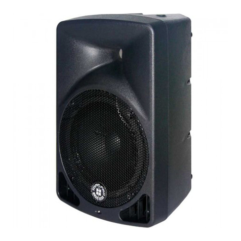
Topp Music Gear TRANS-PORT User manual

TOPPD{
pRO,t="=2,gql-I
TRAilS.POBT
PO RTAB lE SOU 1I II SYSTEM
34
OPERATIO]I TilSTRUGTTOil

TOPP PRO TRANS-PORT
Luxury Portable Sound System
INTRODUCTION
250 Watts of C ear Stereo Sound
Tailored Fuli Response Loudspeakers [4eet High Performance Requ remenis
Buit-in DigiialReverb
Voca npuiPrioriiyAlowsinp!toneloautom€ticallyoverrdea otherinputswlrenasigna is
present on in put one
Four l',,lono I\4 crophone/ L ne rpuls with XLR and 1/4" ba anced inpuls conneclions
Two Stereo lnputs with 1/4 and RCA Conneci ons
Swiich lvode Powe. Supp yA lows UseAnywhere ln The Wor d
Everyihing You Need To Get Starled:
TRANS-PORT N4 xerAmpl fier
- Two Speaker Cab es, 2.8rn
- EC Power Cable
Two Ta ored Fu -Range Speaker Enclosures
- Fu ltransporiation enc csure
' 2 TPt4-5001 m crophones w ih LHT techno ogy
2 qua iiy XLR cab es
A
A
I
-,,1 i
Thissymbolwarnstheuserofdangerousvotage evels ocalized within ihe enclos!::
Th s symboladvises ihe user to read a laccompany ng ieratLrreiorseiec.:-:ii:.'r-.-..
Congralulaiions on your purchase of aT TOPP PRO TRANS-PORT hlg h pedormance. s3rf-.ciia ..: ::.:.tr e
audosystem.YourTRANSPORTincludeseverythngyouwllneediorgreatsouno...An!lvhere.
CarryyourTRANS-PORTasa arge sized suit case. Fl popenihespeekerlalches.andyou dtscore'
two fuli-range speaker cEbinets a powered m xer, dynam c microphones, p us all the cables you neec io
gei started Use your TRANS PORT s qu ck and easy setup, ts ab ity lo cover large aud ences and sirrple
operatlon are the hal marks most desired valLe
The TRANS PORT's control pane Jeaiures four nrono mic / lin e nputs afd tvr'o stereo channe s(s x channe s toia )
The stereo in pul channe s can be used for eith er mono or siereo operation allowing superb flexib lity in input
use. l\,4oreover the ta ored speakers in each speake. enc osure deliver clear, iull range sound w lh excepiiona
aud ence coverage and remarkab e feedback relect on. The self-powered m xer provldes a iota of 250 watis of
h oh quality slereo so u nd.
For vocal operai on, ihe TRANS-PORT s Voca in put Pr or ty feature can be Lrsed to reduce or ower the
background mus c eve as you begin 1o speak ard then restore yo!r background music when yoLr have
flnished speaking. Exper ment with the tone controls dig ial reverb and speaker p acemeni and d scover
the TRANS-PORT S ncred ble power and versalil ty.
IMPORTANT SAFEGUARDS:
- WARNING: TO PREVENT DAIVAGE, FIRE OR SHOCK HAZARD, DO NoT ExPOSE
THIS UNIT TO RAIN OR II/lOISTURE.
. NO USER SERVICEABLE PARTS INSIDE, REFER SERViCING TO QUALIFIED
PERSONNEL AUTHORIZED,
. THIS UNIT IIIUST BE EARTH GROUNDED,
(2)

SAFETY PRECAUTIONS
supplied with TRANS'PORT producis are three p n grounded types
U nder no circumstances should the ground(earth)p n be d sconnected or removed.
YouTTRANS-PORTSystenrieatLrresaSwtch-Ilode'PowerSuppydesignedtooperaleonanyACvotageand
ne frequency to convert AC power wrih maximum effic ency
When iravelling abroad wiih the TRANS-PORT sysiem, as a standard precaut on, a ways check ihe loca vo tage
and sei the voliage se ector switch locEled adjacent io ihe socket on the real of the m xer / ampllfier io ihe
appropriate operaiing ranSe. thls ahclkjtqsl bqBellsrylcd helste !s!uqsl!!q th9-pswelaabLc. The TOPP PRO
TRANS-PORT has two range settings: 115V or 230V .
Fa ure to se ecl the appropriate vo lage range will cause the unit lo go nto protect mode vold any warranty
and may cause da ma qe lo the un i.
For example The Un led Stales ofAmerica is standardized at 117 volts / 60 Hz, Japan operates on 100
vo ts i 50 Hz. For both ofthese counir es ihe range selector must be setto 115V. Countr es in the EEC have
standard zed al230 volis / 50 Hz . However, there are d ffereni types ofAC plLrgs used For a these countries
the selector shouLd be at the 230V posiilon. When using p ug adaplers or operating ln a territory other than
iheone nwhchiheuntwaspurchased,takegreaicaretocomplywithloca safeiy requiremenls and
e ectr calcodes oJ practice
lf you are not sure of the local voltage, wiring codes & colours, AC grounding, or correct procedures for
connection, consult a qualified technician-
The TOPP PRO =iANS ?ORT sound system is supp ied w th a delachable power cab e wilh an IEC
female connecicr and a mare AC conneclor. Depend ng on the terr tory n wh ch the TRANS PORT
system spurchased.thepo\!ercablewl lbesuppliedwilhoneofanumberofrnaleACconneciors
to accom.nodate ihe dilferent safety and code reqLrirements of speciflc counir es. A ACcables
Under no c rc!nrsiances should the ground p n on ihe TRANS PORT or on any of your electr ca
equ pmenl be iited (cui olf or dlsconnected) By io lor,ing the correci proced!res and safeiy
precautions, flsks of severe shock hazard can be mlnimized. Besi of all, avoid operating the
svstern in conjurct on with u ng rou nded or improper y grounded electrical equipment.
l-
TRANSPORTATION LATCHES
To open and c ose your TRANS PORT system. sirnply fo low these g uidel nes:
1_ Paceyourfngertpunderthesafetylatchandgently ifi. When the safety aichhasdlsengaged lfttheman
atctr io remove the speaker.
To replace, posli on the speaker on the ibwer fool ad bring the speaker in 10 close lhe engagemeni with the
tower and laich. Posit on the latch hook over the speakel noich and close ilre aich. The safeiy latch w I
aLrionraiical y engage.
Noier These parls are precis on engineered and no force is needed io secure ihem Careful a gnment of
parts will ensure easy operation.
(3)

MONO MIC / LINE CONTROL FUNCTIONS
a)VOLUNtE Adtuslsthevoume evelofihe ndvldua channe Rotalingtheknobcockwiseincreasesihe
respective channe 's contr bLrtion to ihe 'N4ain Oui" mix, wh e rotaiing I countercLockwise decreases ihe
vo ume. Adtusl ihis coniro after tlre TRANS-PORT s master output leve vo ume has been set.
b) VOCAL INPUT PRIORITY CoNTROL AdtLrsls the level ai wh ch the vo ume of a other channe s are
a!lomatca yreduced n averoiihesourceallachedtothe[.4]c/Line npLril.ThlsuniquefealureDermisauser
to speak while other inputs (such as ba.kgro!nd nrus c) cont nue at temporar y reduced leve s The circu t is
pre-co ume" wh e means it s effect ve regard ess of leve control setiing of ch€nne one Adtust thls control wh e
speaking into a microphone on channe 1 with othe. program mater al nput through another channel. Depend ng
onthedLrrationandleve ofthesgnalbeinglnpultoMci Llnelandthepositonoftheconircl ihecir.uliwl
tr gger a reduction n eve of q he other channe s. The or g na leve s w ll be a!tomatically reslcrea wlren there s
no slgnal present on channe 1. n iypical use, ihe circuit wi return norr.a eve s n about 4 secc.ds !!i1h lhe level
set at a higher or a stronger signa norma evels w ll be restored after approx mately 6 secoiCs Th: c rc! I
has an inteni onally s ow re ease iime which prevenis nterrupt ons then a speaker pauses for lnoLg ht or elfect
Care shou d be taken lo avo d the ir ggerirg on soLrnd from the ma n speakers. At hig h setl nas :n.
m crophone nray heal'the ma n syslenr speakers End ir gger a reduclion n evel. When noi !s ng tlre feature
be sure io turn the contro complete y counterclockwise
e)TREBLE-Adluslslhereatve eveloitlretreblelrequencyconienl Rotallng the knob co!nierc ockw se
decreases the treb e or treb e frequency Iesponse. L kewise rotating the knob c ockw se ncrease ihe treb e or
treb e response is f at" w th no freqLrencies increased or decreased.
f)MlD-Adjusisthereatve eve ofthemldirequencycontent.Rotatngtheknobcounlerclockwisedecreases
the lreble or m d freqLrency response Likew se, rolat ng the knob c ockwlse ncreases ihe treb e or m d frequency
response. When the EQ controls are set al thelr m dd e pos lion. the channe frequency response is "flai" w th no
frequenc es ncreased or decreased
g)BASS -Adjusisthe re at ve levelofthe owfrequencyconieniofthechannell.Rolatingtheknobcockwise
ncreases ihe bass or owfrequencyresponse Likewse rolat ng ihe knob countsrc ockwise decreases lhe bass
or ow lrequency response. L kewise. rotaling the knob coLrnterc ockw se decreases tlre bass or iow frequency
p) DSP / AUX - Adiusts the amount of signa se ni to the Reverb processor, and to the DSP I AUX outpul jack.
Reverb can be used to en hance the sou nd qua ty of any pedormance where appropr ate and des red. ln the full
eft posit on there is no evelsenitothereverbprocesso.orDSPi AUXlack Care shou d be iaken to sei ihe
Reverb relLrrn masier contro lo a middle posii on o. above, berore adjLrst ng evels fiom the ind v dual channel
When lhe reverb / aLrxli ary rn x s sel, overa leve s of reverb can be adjusied at the masier contro
Keep n mind thal while Reverb or eiiecls can enha-ce a rn!slcai perforrnance or presentailon. Too much reverb
can rnake the same performance or presentation un ntelligib e or "mLrffled",Keep yo!r audience n mind when
settjng reverb levels
d) PAN - The Pan contro features a notched pos tion ndcatorandadjustslheperceived"posion ofthemono
s gna from the in pul w lhln the siereo fie d created by the lwo speaker cablnets. Full Lefl or R ght roiat on of
ih s control sends ihe s gnal io the that channe only. w ih no s g nai se nl to ihe other The center posit on sen ds
ihe same amouni oi slgna io both speakers.
STEREO CONTROL FUNCTIONS
I
I
a)STEREOINPUTLEVEL-Adiusisthevdtrmeleve ofihesiereo nputchanne Rotaiing lhe knob clockwise
increases the siereo input channe s conir bution to ihe "N4ain Out m x wh e rotaiing it counterc ockw se
decreases the vo ume. Adiusl ih is contro afler the TRANS-PORT's master oLrtpui leve volume has bee n set.
j)BASS-Adjusisthereatveleve ofihe owfrequencyconlentforihestereochanne.Rotatingtheknob
counterc ockw se, rotat ng the kno b c ockwlse ncreases the bass or low frequency response. Likew se,
rotaiing ihe knob clockw se increases the bass or ow frequency response.
(4)

i)TREBLE-Adtuststherelatveieve oftheireblefrequencyconlent.Roiaiingthe knob counierclockwise
decreases the treb e or lreble irequency response. Likewise. rotating the knob clockwise increases ihe treble
ortreble response s "ilat with no frequencies increased ordecreased.
h)MlD-Adjusisthereatlveleveloitlremidfrequencyconleni Rotatingthe knobcounterclockwsedecreases
the treb e or mid frequency response. Lrkewise, rotating the knob c ockw se ncreases the treble or mid
irequency response. When the EQ controls are set at ilreir noiched or siraighi up pos lion, lhe channel
frequency response s "f at" with no f.equencies increased or decreased.
p)DSP/AUX Adluststheamounlofsigna senllotheintma Reverbprocessor,andtotheDSP/AUXoutpui
iack ln the iLrll eit posit on ihe control :s effect ve y oif CaIe shou d be taken lo set the Reverb relLrm masier
contro to a middle positron or abov-a, before adjusilng evels from the ndivjdua channe s. When lhe reverb /
auxiliary mix is set, overall levels of reverb can be adjLrsied ai ihe master control.
d) BALANCE - The balance controlfeatures a nolched positlon nd caior and adiusts the perceived"posliion
ofthe monosigna frofi lhe in put w ihin the stereo fie d crealed by ihe iwo speakers. Full Lefl of Right rotailon
ofthlsconirolsendsthesigna toihethatchannelony,wthnosigna senitolheother.Thecenterposilion
sends the sarne amounl of signa tobothspeake
MASTER CONTROL FUNCTIONS
,,S] (@) .I :***
--
-
,:*# +++
#- *;
#:,
+
=
+
=
k & l) IMASTER VOLUME LEVEL CONTROLS TheLeftandRightMasterVolumeControlsadlusttheoutpui
vo ume of ihe TRANS-PORT. The iVaster contro s feature noiched position indicators. For the majoriiy of
appllcailons the TRANS-PORT sysiem has been balanced to operate with these conirols at their notched 12 o'clock
positions. ln s tuations where more vo ume s required ihe master controls can provide ar addllional 6 dA of gain
when turned to the r qhi of the center posilion.
Sei ihe system up in the normal manner and adlusl leve s as necessary. Raise the masler vo ume coniro s
beyond iheir 13 o clock pos lions or y after increas ng the ind iv dual channel eve contro s
TRANS-PORT s internal anrplifLers have on board processing deslgned io optimize ihe system ,s performance when
used wilh the custom deslgned TRANS-PORT spe3kers
m)STEREO / DUAL SELECTOR SWITCH AlowstheTRANS-PORT'spowerampstobeconfigr.rredassiereoor"
dual- mono" ln the Siereo mode, the syslem operates as a tradit onalstereo power m xer / anplif er. in ihe Dtral
mode.thechanne levelcontrolscontrolsetthe evelforihe[,'lainmix(LEFTmastervolumecontrol)TheRev/
Auxconirolssetthe ndvidua channe levelsfortheNlonito(RlGHTmastervoumecontroL).
When the Dua mode posit on is selected wiilr the sw tch, the Pan and Balance conirols beconre in operative
(you have selecied a mono s-.llins for lhe ouip!t). Addit onally,lhe inierna reverbison'lysenttothellAlN
speaker ouiput. Reverb s not availab e to ihe vlON TOR speaker output The reverb evel sends for the I\,4AlN
r. x are also control ed from the channe! DSP /AUX channe controls. The overall reverb leve 10 the [,4A N m x
is controlled by the Reverb IVasier Conlrol.
c) SYSTE[4 EOUALIZER - Adjust the amount of frequency increase or decrease in the cha nnel. The eft and r]ghl
channe s are adlusted simu ian eous y at same time and same pace Set frequenc es a.e al 31H2,63H2,125H2,
2S0Hz,SAjHZ,lKH,z,2KHz,4KHz,SKHzandl6KHz,adlustingrangewthn+/-l2dBiWhentheslidngsiicksatthe
middle position, the freq!ency response is f at" with no frequencies increased or decreasedi When sljding the stick
up ncreases the frequency response of ihat band, when slid ing the stick down decrease thai band's frequency
response. To set the EO slartwiihthscontrolflomthemddle("0dB"rnarked)posiiion.Simplyslidethestcks
untilyourdesired so u nds are there.
DSP EFFECTS
,,@) ,,@)
"@j
pIDSP/AUX-Adjuststheamountofreverbsigna leve senttoihemlxoroutput.Rotatngtheknobclockwise
increasesthereverbsgnalsentiothemainmx Whentheknobis nitsfullcountercockwseposiiion,there s
no reverb heard n the mix.
n) DELAY - Adjust the length oi delay time of the s gnal. Rotatlng the knob clockwise lncrease the de ay lime whlle
rotatlng ihe knob counterciockw se decreases the de ay time.
(5)
o
J61
@
61
\ got*
t
rd n,lO q-* r5
eiea a'{fi9l
o)REPEAT-Adjusttheamountsofthesgna ioberepeated Roiat ng the knob clockwise rncreases the repeaiing
eil clency whi e rotating the knob counterclockwise decreases the repeat ng efficiencv
You wi noilce that ihe in pul jacks and channelconiro s are co or coded. This ls done 10 easily !dent ly wh ch sel
of controls is assoc ated with whlch nput connections.
MIC / LINE STEREO INPUTS
q) lMlC INPUT JACK - P ug youl mjc.ophone n here. Thls ihree pin XLR ba anced fema e nput in put s gnals from
in put sig na s from bass ir.pedance m crophones.
u)LINEINPUTJACK Pl!gyourlnstrurnentinhere.Thls 1/4nchbalanced nputjacksLrtedfor!sewithitems
hav ng a lin e evel output such as high lmpedance m crophones. keyboards, dr!m mach nes outboard effects
eic. ll accepts both ba anced and !nba anced cables
r & s) STEREO INPUTS - Steteo phono (RCA) in pui jacks and 1/4" TRS iacks (wired ior Tlp=Lell. Rins=R oht and
Sleeve=Ground.the st:ndard fofmat oi conrmerclal v ava ab e cab es)deslgned for use w th a iape plaver.
CD player or any olher stereo soulce. Use th ese jacks for connecting tlre output ol a compuler sound card o.
other sirnilar device lo your TRANS-PORT Adapters ihai converl an 'l / 8" male plug lo RCA male phono plugs are
readliy ava able ai electronics stores. Note: These connectors are sel at a constant"l ne level"
aa)STEREO OUT - The Tape Out RCAtacks provLde a m x o!1put that is ndependeniofihelvlasterLevelControls.
Connect these to tlre npuls of a record ng dev ce. s!ch as 2 cassette oI DAT Iecorder to record your eveni.
Changes maCe during ihe performance. to the inp!t leve conlrols, ctranne EQ and reverb controls w be heard
ntheTapeOulmix.Clrangesmadetothernaster eve controlswil no! eiiect the leve ofiherecording AdlLrsi
record ng leve s accordlng to the instrLrctlons on your recording dev ce.
AUXAND FOOT SWITGH JACKS
T)REV/AUXSEND'PlLrgyourexlernaleffectssgfalprocessorinhere.AthoughtheTRANS_PORTsaready
equ pped with on -board dig la reverb an external effects signa processor n here. A though the TRANS PORT s
a ready equipped w:th on -board dig ta reverb Bn extelnal eflects signa plocessor can be incorporated lnto
theTRANS-PORTsssna iow.Thisl/4inchoutpuijacksdesgnedtofeedtheTRANS-PORTseffectsbussignal
io an external s gnal processing diver, such as a dlgitaL delay or a chorus.
t)AUXRETURN-Pugyourexternaleflectssigna processoisoutputsgna inhere. Th s 1/4 inch nputstereo
lack is designed to accepi signa s from an externa process ng device. such as a digiia delay or a chorLrs !nit.
Th is ln p!t can also be used as a stereo ln put w ih the vo urne controLled al lhe rnasiel vo ume knobs.
v) FOOT SWITCH - The Foo t sw lch connector allows the flerna reverb retLrm to be muted, or shout off, throLrgh
the use of a s nrple fooi operated sw ich.The foot slviich shou Ld be wlred to connecl the iip to the sleeve to turn lhe
reverb off, and requ res a standard speaker or nsirument cab e
y&z)AMPLIFIERSEND/RETURNJACKS Eachchanne oftheampiflerhasaSendandReiumiack.Thesejacks
provide a po nt io patch naneqLralzer,orotherprocessorlntolhesoundsysiem.Thesgnalatthesendlackis
ocaied afier ihe mixer sect on and before the power ampl!i eI The send jack shou ld be connected to the ouiptrt
ofihe eYiernald-^vi.e
w&x)SPEAKEROUTPUTS Thesearespeakerleve (powered)ouipLtjacksdesignedtofeedeachofyour
TRANS-PORTP speaker enc osures. Use the enc osed cables(or other speaker cab e) to connect the TRANS_PORT'
s speakers io the powertower
bb)PowERSWITCH'TurnslheACpowerONandOFF Whentheswlclris ntheOFFpostion yourTRANS-PORT
is compleie y shut down.
(6)

REAR PANEL
CONNECTOR/LINECORD'-ineTRANS PORT is eq u ipped w th a grounding iype IEC s!pply cord to redLrce the
possibility of shock hazard. Be s-re to co.nect ii to a grounded AC recepiac e. DO NOT ALTER THE AC PLUG
The power nra ns(AC)fuse and fuse holder are under the IEC(power cord) socket Replace me nt
fuses mLrsl be oflhe same rat ng(6A 250V)and s ze as or g na y equ pped. To replace € b own
fuse rer.ove the EC po!rer cord. Pu out the fuse holder and f nd the spare f!se ins de.
REo Connecting with DC power supply externall
l.:;. o ro r rhe DC .on ect no p -o lo .he -d pdrelof . e po,re, .o{e'
Biui and DC power supp V lacl
ffi
YoUTTRANS-PORT system s capab e of runn ng on battery power. The off-white plast c connector on the rear of
your TRANS-PORT s the DC power if pui connector for connect ng the TRANS-PORT w lh +i - 48 V battery pack.
REAR STORAGE COMPARTMENT
A small slorage compariment can be found on ihe rea r of ihe TRANS-POR I iower. To access this compartmeni,
s mp y I fl ihe laich and pu open the siorage door. This compartmeni s ldea ior storlng cab es nricrophones or
other iienls !!hen yo! are transport ng yourTRANS-PORT.
SET-UP AND CONNECTIONS
Before turn ng on ihe Power p ease read and heed ihe safeiy warnings on page 4
t s wise 1o estab ish a rout ne for conneciing and power ng up your sound systern Provided you have a proper y
grounded AC out et or out et strlp w th sLrii clent power hand ng capacily. plug a I sound system equipment nto
thesameoullelorstrip.Thsw lenhance system safety and performance TakecarethatlheACcircuit s
capable of handi ng the pea k power dernands oi your syslem Cons! I the producl handbooks or a qua illed
e ectri. a. I in doubt
!'/nen setting up, be sure to follow these simple s€t'up g u idelines:
l.First turn all channel Level. V P(channe i ONLY)and Rev/Aux controls to their full counterc ockwiselOFF)
posit ons. Nexi, p ace a EQsiicks nthemiddlepositon(c'positon),a Panandl\4astercontrosatl2o'cock
n ihe r center notched pos rio n s. Be sLrre io set the appropr ate in put (m c / ine switch pos tion)for the source
2.Next connect ea ch speaker cab e to the appropr ate efl & R ght Spea ker ouip!is on the rear tower and on
each speake.fron! pane w lh the enclosed cables.
3 Co rnecl a sources sLrch as m crophones. tape decks. keyboards elc., nto the apFropriate nputs.
4.Finally.check the ocal voltage and set the vo lage se ector sw tch ocated adiacent to the power in put socket
onlherearofthemixerrampifertotheapproprialeoperalifsranse(S,.eSafeiyPrecauiionsofpage:1 )Plugthe
power cable into the IEC(power cord)socket end lo a proper y srounded 3 wire AC power outlei.
POWERING UP
Turn the Power Swltch to the ON posit on. The Power LED w ll um nale green and the sysiem will turn on f
oiher povrered eq!ipmeni siobeattachediolhesystem,ii sawaysadvisabetolurnonyourTRANS-PORTlast.ln
lh s way any trans ent spik€s and lh!mps ca used by other equ pment w not be amp if ed and sent io you r
syslemspeakers Forlhesamereasonsit sadvsabLeloturnoiiyourlRANS-PORTsystemfirsibeforeiurningoff
lhe attached eq ulpment.
Shou d the Powe. LED not uminate when the rear pane power switch s operated check your power
connect ons and retry Shou d the Power LED stil fa 10 illum nate after you have conf rmed the power
connect ons, d sconnect a cablesandchecklheTRANS-PORTfuses Besuretoreplaceanybownflrseswthfuses
ofthecorrecivaue Reconnectthepowerandspeakercablesandturntherearpane powerswtchon
Re-setihesysiembyiurningonihepowerswi4 tinepowerLEDrl umnalesred the syslem ls indicating €
thermal prolect mode or coo ing prob em Be sure to check the a r ln et ii ter at the base ol the un t by removing
ii and mak ng sLre 1is clear oi debris.
Turnpoweroffandwaliorafe\,1rmn!tesa owngheatlodissipateandiheTRANS-PORTtoreseljtself. iafterdong
so tlre Power LED contin!es io glow red ihls indicaies a fault with your syslem and yoLr shoLr d co nsu I an
auihorlzed TOPP PRO service center.
(7)

lf no aud o is presenl in one of the speakers, check to see if your control seltings are correct. Next. un plug the
cab e from your work ng speaker and reconnect it to the other speaker. lf the second speaker now works, thls
ndlcates lhat the firsl cable is bad, and shou d be repaired or rep aced.
SET.UP SYSTEIM VOLUIlIE AND LEVELS
To sel system volume and operat ng levels, be sure io fo ow ihese s mp e sei.up gu de ines:
l.Firsi,slowly raise ihe large Left and R ghl Masier vo ume coniro s io their 12o'clock notched posllions.
2.Useamcrophone(orothersource)inihesameposlionas twilibeusedonstageandinlhemanner nwhch
it wil be used for ihe event. Siow y bring up the appropriaie channelinput level coniroll slening ior the onset of
feedback or howling or until the required leve is reached. Have a helper walk"the audience area to make sure
coverage and leve s are suff cient for your needs. The sysiem's overa volume can be raised s mp y by rotating
the Leit and Right [r]aster vo ume coniroLs io the desired level
3. Cons der the applicaiion and needs of the event and sel ihe Syslem EQ contro appropr ate y Th s s besi
achieved by playing recorded maier al of ihe same iype as your show program, or by having an asslstani speak
inlo the m crophone while you isten n the audlence area.
For pub ic address (spoken vo ce), it is adv sa ble to rotate the System EO st cks up to enhance the
midandhlghfrequences,andir'rtlhelowfrequencyconierlForargeoutdoorspacesthswillalsogvelhe
max mum headroom and output capabll ly Careflrlly consider the ind iv d!al event's needs and set your control
ior the maxirn um eff ect.
POWER TOWER
ln setting up lhe system. the TRANS-PORT [,4 xing console should deal]y be placed whe.e system performance
can be evaluated by the operalor. f no ongoing adjustments wil be necessary the mixer may be p aced conve-
nienlly and where the cabie engths allow
TakecareloplacethePowerTowertherelhecabeswil noltrpanyone Al cables should be carefully secLred
ThestoragecomparimenlintherearoftheTowercanhodcables microphonesandolhersystemparts Toopen
simp y slide the caich upwards and pull open.
The ma ns (AC) fuse holder s under the IEC (power cord) sockel on the r ght rear oflhe Tower. To change a fuse,
remove the EC plug and. us ng an appropr ate tooi pu oul the fuse holder Note there is a spare fuse if the fuse
holderiihe TRANS'PORT ut lizes a T6A 250V fuse Only replace fuses with one oi an ldenlicalvalLe and size.
SPECIFICATIONS
Frenquency Response20 l1z ta 20 k{z 1dB (ai send output)
30 Hzto20kHz ldBlaispeakeroutpui,wth processorthresholdexceeded)
Distortion <0.05%. 20 Hz to 20 kHz I dB below rated output
System Signalto Noise Ratio >80d8@1\d "A WTD
PowerOutput l25Wichcontinuousaveralepower,Sohm,botlrchannelsdrivenwithTFlD <1%
lnpul lmpedance (Channels 1-2"3 XLR and 1/4") "L,lic"switchpostion:2kohm
"L ne" sw tch posiilon:33 k ohm
lnput lmpedance (Phono and Stereo Channel 1/4") 33 k ohm
Nlax.lnputLevel l\4ic:'7dBu Line: 30dBu Stereo: 26dBu
Return lnput lmpedance 47k ohm
Fuse type T6A?50V
Trans-port System Widlh: 845 mm He ghlr 760mm Deplh: 330 mm We ghi: 30kgs
Speakers Widih: 330 mnr He ghlr 760mm Deplh: 330 mm Welghi: 8.2kgs
PowerTower Wdth:330mm #Bghi:760mm Depih:21Ornm Wejght:13.5kgs
Tower Footprint 448 x242 mn
Microphone Dynam c Cardiold balanced
Microphone Cable XL Ua e to XL Fema e
SpeakerCables 1l4h.Ia1l4 n,22m0dBu sreferencedto0.TT5volisrms
Table of contents
Other Topp Music Gear Speakers System manuals

Topp Music Gear
Topp Music Gear T-Array SAT28P User manual

Topp Music Gear
Topp Music Gear APEX 18SA User manual

Topp Music Gear
Topp Music Gear XCS 12A User manual

Topp Music Gear
Topp Music Gear KS8A User manual

Topp Music Gear
Topp Music Gear Ready 12 User manual

Topp Music Gear
Topp Music Gear Argo 8 User manual

Topp Music Gear
Topp Music Gear X 8A User manual

Topp Music Gear
Topp Music Gear TPS215NEO MKII User manual

Topp Music Gear
Topp Music Gear ARGO 8A User manual