Operation and Maintenance Manual
5/13
(2) In this case, measure the concentricity and parallelism of the coupling halves (the both shafts) respectively at
4 points spaced at 90°. The specified accuracy shall be within 0.1 mm respectively.
(3) Check the driver’s rotating direction without fail, before connecting one coupling half (pump side) and other
coupling half (driver side) together. The correct rotating direction of the pump is shown with an arrow mark on
the side face of the bearing pedestal, that is, clockwise direction viewing from the driver side.
(4) If the rotating direction is correct, connect two coupling halves together.
(5) Further, if the temperature of pumping liquid exceeds the normal temperature range of changes widely during
pump running, the direct coupling will possibly deviate a little. In such case, therefore, use the coupling with
large flexibility.
1.3. Piping
After completion of the direct coupling work, the suction and discharge pipes must be connected to the
respective flanges of the pump. Perform the piping connection with good care for the following items.
(1) When connecting the suction and discharge pipes, take proper measure to prevent piping load from directly acting
on the pump. Direct load to the pump by piping would cause trouble.
(2) The suction line must be installed in upward slope (about 1/50) toward the pump prevent air leak and air pocket in
the case of suction lift. And it must be installed in downward slope reversely in the case of forced suction.
(3) Take to minimize various losses of the suction pipe and avoid sudden changes of cross-section and use of abrupt
bends in the suction piping. Select the pipe size such that the flow velocity in the pipe does not exceed 3 m/s.
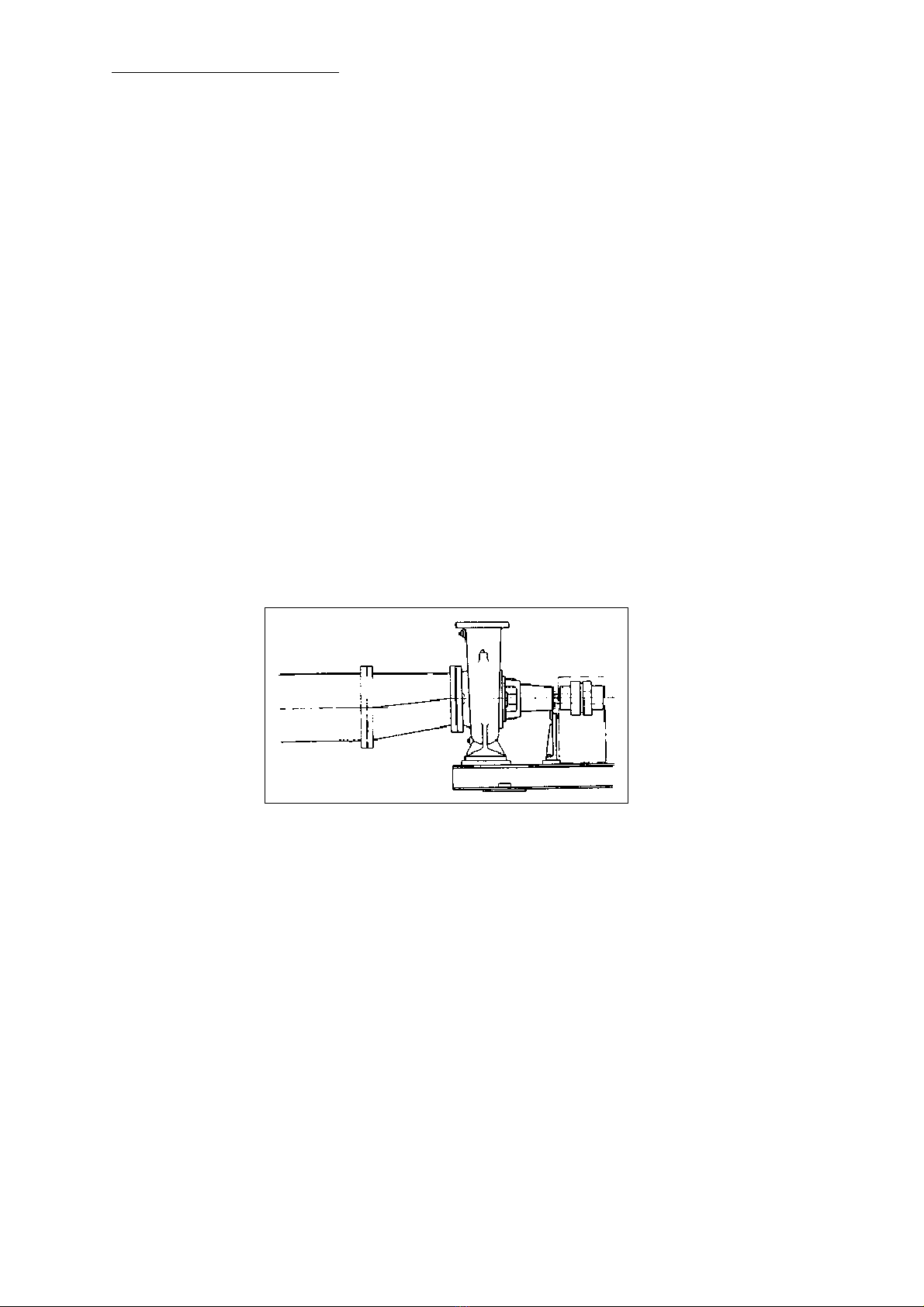
(4) When the suction pipe size is different from the pump suction nozzle size, use an eccentric tapered pipe to connect
the suction pipe and pump suction nozzle and to prevent air pocket. (Fig. 3)
(5) When a sluice valve is installed on the discharge line, located the valve as close as possible to the discharge
nozzle of the pump. Further, when a check valve and a sluice valve are provided o the discharge line, locate the
check valve between the pump discharge nozzle and the sluice valve.
(6) In case of starting operation of a plant for the first time, various foreign matters remain in its pipe line and may
possibly flow into the pump. In such case, therefore, provide a strainer on the suction line for complete removal of
foreign matters. The strainer used shall have the passing area equal to 3 ~ 4 times the sectional area of the suction
pipe. If the strainer is clogged with foreign matters during the pump running, readings of the suction line pressure
gauge will fluctuate. Sometimes, clean the strainer to remove foreign matters.
(7) When external flushing water piping is provided, clean adequately the flushing water pipe before connecting.
(8) The temperature of pumping liquid significantly different from the atmospheric temperature would cause the pipe
line to shrink or expand. In such case, install a flexible pipe, etc. on the pipe line to prevent the load by shrinkage o
the pump.
(9) After completion of the piping work, recheck that the pump is free from abnormal load by piping as well as free from
alignment deviation, and make re-adjustment when required upon rechecking.
- 3 -