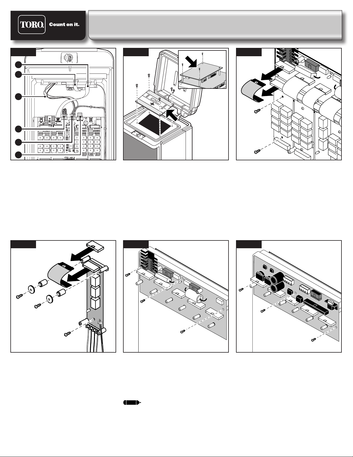
Toro Network LTC Plus-to-Network VP User manual


This manual suits for next models
1
Popular Industrial Electrical manuals by other brands

Eaton
Eaton XTCE580N Series Instruction leaflet

Siemens
Siemens SIVACON 8PS BD2 Series installation instructions

S&C
S&C Vista Series instruction sheet

Murata
Murata GQM1875C2E1R1WB12 Series Reference sheet

Murata
Murata GJM0335C1H5R4CB01 Series Reference sheet

Murata
Murata GRM1885C1H5R9CA01 Series Reference sheet

Murata
Murata GRM2165C1H201JA01 Series Reference sheet

Murata
Murata GRM033R71H271KA12 Series Reference sheet

Murata
Murata GRM216R71H302JA01 Series Reference sheet

PCB
PCB 1102-01A Installation and operating manual

Murata
Murata GRT21BC81E335ME13 Series Reference sheet

Murata
Murata GRM32ER7YA106KA12 Series Reference sheet

Igema
Igema LG40-CS Installation and operating instructions

Murata
Murata GRM033C71C104ME14 Series Reference sheet

Power Electronics
Power Electronics SDRIVE DB Series Getting started manual

Murata
Murata GRM155R61A103KA01 Series Reference sheet

Murata
Murata GQM22M5C2H1R6BB01 Series Reference sheet

Murata
Murata GRM31CC81E226KE11 Series Reference sheet