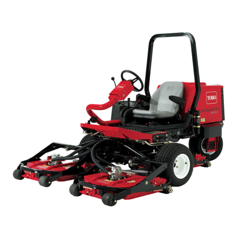
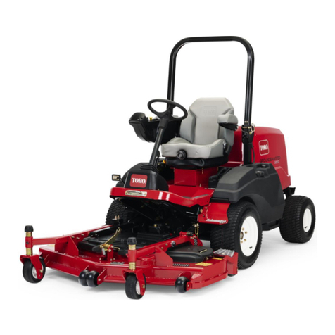
Toro 31200 User manual

FormNo.3397-630RevA
Groundsmaster®3604-Wheel
DriveMulti-PurposeMachine
ModelNo.31200—SerialNo.316000001andUp
Registeratwww.Toro.com.
OriginalInstructions(EN)*3397-630*A

WARNING
CALIFORNIA
Proposition65Warning
Dieselengineexhaustandsomeofits
constituentsareknowntotheStateof
Californiatocausecancer,birthdefects,
andotherreproductiveharm.
GenuineTorosparkarrestersareapprovedbytheUSDA
ForestryService.
ItisaviolationofCaliforniaPublicResourceCode
Section4442or4443touseoroperatetheengineonany
forest-covered,brush-covered,orgrass-coveredlandunless
theengineisequippedwithasparkarrester,asdenedin
Section4442,maintainedineffectiveworkingorderorthe
engineisconstructed,equipped,andmaintainedforthe
preventionofre.
Introduction
Thismachineisaride-on,rotary-blademachineintended
tobeusedbyprofessional,hiredoperatorsincommercial
applications.Itisprimarilydesignedforcuttinggrass
onwell-maintainedlawnsinparks,sportselds,andon
commercialgrounds.Itisnotdesignedforcuttingbrushor
mowinggrassandothergrowthalongsidehighways,orfor
agriculturaluses.
Readthisinformationcarefullytolearnhowtooperateand
maintainyourproductproperlyandtoavoidinjuryand
productdamage.Youareresponsibleforoperatingthe
productproperlyandsafely.
YoumaycontactTorodirectlyatwww .Toro.comforproduct
safetyandoperationtrainingmaterials,accessoryinformation,
helpndingadealer,ortoregisteryourproduct.
Wheneveryouneedservice,genuineToroparts,oradditional
information,contactanAuthorizedServiceDealerorToro
CustomerServiceandhavethemodelandserialnumbersof
yourproductready.Figure1identiesthelocationofthe
modelandserialnumbersontheproduct.Writethenumbers
inthespaceprovided.
Figure1
1.Modelandserialnumberlocation
ModelNo.
SerialNo.
Thismanualidentiespotentialhazardsandhassafety
messagesidentiedbythesafety-alertsymbol(Figure2),
whichsignalsahazardthatmaycauseseriousinjuryordeath
ifyoudonotfollowtherecommendedprecautions.
Figure2
1.Safety-alertsymbol
Thismanualalsouses2wordstohighlightinformation.
Importantcallsattentiontospecialmechanicalinformation
andNoteemphasizesgeneralinformationworthyofspecial
attention.
©2015—TheToro®Company
8111LyndaleAvenueSouth
Bloomington,MN554202
Contactusatwww.Toro.com.
PrintedintheUSA
AllRightsReserved

Contents
Safety...........................................................................4
GeneralSafety.........................................................4
SafetyandInstructionalDecals.................................4
Setup............................................................................9
1AdjustingtheROPS..............................................9
2CheckingtheTirePressure.....................................9
3CheckingtheFluidLevels.....................................10
ProductOverview.........................................................10
Controls...............................................................10
Specications........................................................14
Attachments/Accessories........................................15
BeforeOperation......................................................15
BeforeOperationSafety..........................................15
CheckingtheEngine-OilLevel.................................16
CheckingtheCoolingSystem...................................16
CheckingtheHydraulicSystem................................16
FillingtheFuelTank...............................................16
UsingtheRolloverProtectionSystem(ROPS)............17
TheSafetyInterlockSystem.....................................18
SelectingtheSteeringMode.....................................18
PositioningtheStandardSeat...................................19
PositioningtheDeluxeSeat......................................19
Raising/LoweringtheSeat.......................................20
DuringOperation.....................................................21
DuringOperationSafety.........................................21
ThinkSafetyFirst...................................................22
StartingandStoppingtheEngine..............................22
DrivingtheMachine...............................................23
StoppingtheMachine.............................................23
OperatingtheMower..............................................23
OperatingTips......................................................24
AfterOperation........................................................24
AfterOperationSafety............................................24
PushingtheMachinebyHand..................................24
HaulingtheMachine...............................................25
Maintenance.................................................................26
RecommendedMaintenanceSchedule(s)......................26
DailyMaintenanceChecklist....................................27
PremaintenanceProcedures........................................28
Pre-MaintenanceSafety...........................................28
PreparingtheMachineforMaintenance.....................29
UsingtheHoodPropRod.......................................29
Lubrication...............................................................30
GreasingtheBearingsandBushings..........................30
EngineMaintenance..................................................30
ServicingtheAirCleaner.........................................30
CheckingtheEngine-OilLevel.................................32
ChangingtheEngineOilandFilter...........................32
ServicingtheDieselParticulateFilter(DPF)...............33
ServicingtheDieselOxidationCatalyst
(DOC)..............................................................33
FuelSystemMaintenance...........................................34
ServicingtheWaterSeparator...................................34
ServicingtheEngineFuelFilter................................34
CheckingtheFuelLinesandConnections..................34
CleaningtheFuelPick-UpTubeScreen.....................34
ElectricalSystemMaintenance....................................35
ElectricalSystemSafety...........................................35
CheckingtheFuses.................................................35
ServicingtheBattery...............................................35
StoringtheBattery..................................................36
DriveSystemMaintenance.........................................36
CheckingtheTirePressure......................................36
CorrectingSteeringMisalignment.............................36
CoolingSystemMaintenance......................................37
CoolingSystemSafety.............................................37
CheckingtheCoolingSystem..................................37
CleaningtheRadiator..............................................37
BrakeMaintenance....................................................38
AdjustingtheServiceBrakes....................................38
AdjustingtheParkingBrake.....................................39
BeltMaintenance......................................................39
CheckingtheAlternatorBelt...................................39
ControlsSystemMaintenance.....................................40
AdjustingtheTractionDriveforNeutral....................40
AdjustingtheMaximumGroundSpeed.....................40
AdjustingtheMow-SpeedLimiter.............................41
HydraulicSystemMaintenance....................................42
HydraulicSystemSafety..........................................42
CheckingtheHydraulicSystem................................42
ChangingtheHydraulicFluidAndFilter....................42
Cleaning...................................................................43
WasteDisposal.......................................................43
Storage........................................................................44
PreparingtheEngine..............................................44
PreparingtheMachine............................................44
3

Safety
ThismachinehasbeendesignedinaccordancewithENISO
5395:2013andANSIB71.4-2012.
Improperuseormaintenancebytheoperatororownercan
resultininjury.Toreducethepotentialforinjury,comply
withthesesafetyinstructionsandalwayspayattentionto
thesafetyalertsymbol,whichmeansCaution,Warning,or
Danger—personalsafetyinstruction.Failuretocomplywith
theinstructionmayresultinpersonalinjuryordeath.
GeneralSafety
Thisproductiscapableofamputatinghandsandfeetand
ofthrowingobjects.Alwaysfollowallsafetyinstructionsto
avoidseriouspersonalinjury.
Usingthisproductforpurposesotherthanitsintendeduse
couldprovedangeroustoyouandbystanders.
•ReadandunderstandthecontentsofthisOperator’sManual
beforeyoustarttheengine.Ensurethateveryoneusing
thisproductknowshowtouseitandunderstandsthe
warnings.
•Donotputyourhandsorfeetnearmovingcomponents
ofthemachine.
•Donotoperatethemachinewithoutallguardsandother
safetyprotectivedevicesinplaceandworkingonthe
machine.
•Keepclearofanydischargeopening.Keepbystandersa
safedistancefromthemachine.
•Keepchildrenoutoftheoperatingarea.Neverallow
childrentooperatethemachine.
•Stopthemachineandshutofftheenginebeforeservicing,
fueling,oruncloggingthemachine.
Improperlyusingormaintainingthemachinecanresult
ininjury.Toreducethepotentialforinjury,complywith
thesesafetyinstructionsandalwayspayattentiontothe
safety-alertsymbol,whichmeansCaution,Warning,or
Danger—personalsafetyinstruction.Failuretocomplywith
theseinstructionsmayresultinpersonalinjuryordeath.
Youcanndadditionalitemsofsafetyinformationintheir
respectivesectionsthroughoutthismanual.
SafetyandInstructionalDecals
Safetydecalsandinstructionsareeasilyvisibletotheoperatorandarelocatednearanyareaofpotential
danger.Replaceanydecalthatisdamagedorlost.
93–6696
1.Storedenergyhazard—readtheOperator'sManual.
117–4979
1.Rotatingbelt—Keepguardinplace
117-3276
1.Enginecoolantunder
pressure
3.Warning—donottouchthe
hotsurface.
2.Explosionhazard—read
theOperator'sManual.
4.Warning—readthe
Operator'sManual.
4

117-3270
1.Warning—donottouchthehotsurface.
2.Cutting/dismembermenthazard,hand;entanglement
hazard,belt—stayawayfrommovingparts,keepallguards
andshieldsinplace.
117-3272
1.Warning—readtheOperator'sManual;failuretousthe
rolloverprotectionsystem(ROPS)canresultininjuryin
theeventofarollover;wearaseatbeltwhenaROPSisin
place,donotwearaseatbeltwhenROPSislowered.
106-2353
1.Electricalpowerpoint
117-4766
1.Cutting/dismembermenthazard;fan—stayawayfrom
movingparts,keepallguardsandshieldsinplace.
98-4387
1.Warning—wearhearingprotection.
120-6604
1.Thrownobjecthazard—keepbystandersawayfromthe
machine.
2.Cutting/dismembermenthazardofhand,mower
blade—stayawayfrommovingparts,keepallguardsand
shieldsinplace.
3.Cutting/dismembermenthazardoffoot,mowerblade—stay
awayfrommovingparts,keepallguardsandshieldsin
place.
5

107-2908
1.Thrownobjecthazard—keepbystandersasafedistance
fromthemachine.
2.Thrownobjecthazard—donotoperatethemowerwiththe
deectoruporremoved,keepthedeectorinplace.
3.Cutting/dismembermenthazardofhandorfoot,mower
blade—stayawayfrommovingparts.
106-9206
1.Wheeltorquespecications
2.ReadtheOperator'sManual.
117–2718
115-0492
1.Heightofcut(topnumber:mm,bottomnumber:inches)
117-3273
1.Warning—readtheOperator'sManual.6.Thrownobjecthazard—keepbystandersasafedistancefrom
themachine.
2.Warning—donotoperatethismachineunlessyouaretrained.7.Warning—locktheparkingbrake,stoptheengineandremove
theignitionkeybeforeleavingthemachine.
3.Warning—weartheseatbeltwhenseatedintheoperator's
position.
8.Tippinghazard—lowerthecuttingunitwhendrivingdown
slopes;slowmachinebeforeturning,donotturnathigh
speeds
4.Cutting/dismembermenthazardofhandorfoot—removethe
ignitionkeyandreadtheinstructionsbeforeservicingor
performingmaintenance.
9.Cuttinghazardofhandorfoot—stayawayfrommovingparts;
keepallguardsinplace.
5.Warning—wearhearingprotection.
6

107-2916
1.Removetheignitionkeyandreadthe
Operator'sManualbeforeservicingor
performingmaintenance.
2.Thrownobjecthazard—donotoperate
themowerwiththedeectorupor
removed,keepthedeectorinplace;
keepbystandersasafedistancefrom
themachine.
3.Cutting/dismembermenthazardof
handorfoot,mowerblade—stayaway
frommovingparts.
125-4399
1.Lowerthedeck4.Slow7.Engine—start
2.Raisethedeck5.Engine—stop8.2-wheelsteering
3.Fast6.Engine—run9.4-wheelsteering
131–1946
1.ReadtheOperator’sManualformoreinformationonservicingthemachine.
7

BatterySymbols
Someorallofthesesymbolsareonyourbattery
1.Explosionhazard6.Keepbystandersasafe
distancefromthebattery.
2.Nore,opename,or
smoking
7.Weareyeprotection;
explosivegasescan
causeblindnessandother
injuries.
3.Causticliquid/chemical
burnhazard
8.Batteryacidcancause
blindnessorsevereburns.
4.Weareyeprotection9.Flusheyesimmediately
withwaterandgetmedical
helpfast.
5.ReadtheOperator's
Manual.
10.Containslead;donot
discard
8

Setup
LooseParts
Usethechartbelowtoverifythatallpartshavebeenshipped.
ProcedureDescriptionQty.Use
1Nopartsrequired–AdjusttheROPS.
2Nopartsrequired–Checkthetirepressure.
3Nopartsrequired–Checkthelevelsofthehydraulicuid,
engineoil,andcoolant.
MediaandAdditionalParts
DescriptionQty.Use
Operator'sManual1Readthemanualbeforeoperatingthemachine.
Engineoperator'smanual1Readthemanualbeforeoperatingthemachine.
PartsCatalog1UsethePartsCatalogtoreferencepartnumbers.
OperatorTrainingMaterial1Reviewbeforeoperatingmachine
1
AdjustingtheROPS
NoPartsRequired
Procedure
1.Removethehairpincotterpinsandthepinsfromthe
rollbar(Figure3).
2.Raisetherollbartotheuprightpositionandinstallthe
2pinsandsecurethemwiththehairpincotterpins
(Figure3).
Note:Ifyoumustlowertherollbar,pushthebar
forwardtorelievepressureonthepins,removethe
pins,lowerthebarslowly,andsecureitwiththepinsso
thatitdoesnotdamagethehood.
Figure3
1.Rollbar3.Hairpincotter
2.Pin
9

2
CheckingtheTirePressure
NoPartsRequired
Procedure
Thetiresareoverinatedforshipping.Therefore,release
someoftheairtoreducethepressure.Checkthetire
pressure;refertoCheckingtheTirePressure(page36).
3
CheckingtheFluidLevels
NoPartsRequired
Procedure
1.Checkthelevelofthehydraulicuidbeforestarting
theengine;refertoCheckingtheHydraulicSystem
(page42).
2.Checktheleveloftheengineoilbeforestartingthe
engine;refertoCheckingtheEngine-OilLevel(page
32).
3.Checkthecoolingsystembeforestartingtheengine;
refertoCheckingtheCoolingSystem(page37).
ProductOverview
Controls
Becomefamiliarwithallthecontrolsbeforeyoustartthe
engineandoperatethemachine.
TractionPedal
Thetractionpedal(Figure4)controlstheforwardandreverse
operation.Pressthetopofthepedaltomoveforwardandthe
bottomtomoverearward.Groundspeeddependsonhow
faryoupressthepedal.Fornoload,maximumgroundspeed,
fullypressthepedalwhilethethrottleisintheFASTposition.
Tostopthemachine,reduceyourfootpressureonthe
tractionpedalandallowthepedaltoreturntotheCENTER
position.
Figure4
1.Parkingbrake4.Tractionpedal
2.Brakepedal5.Mow-speedlimiter
3.Tilt-steeringpedal
Mow-SpeedLimiter
Themow-speedlimiter(Figure4)limitsthetractionspeedof
themachinewhenyouipitforward.
BrakePedal
Usethebrakepedalinconjunctionwiththebrake-pedallatch
toengageanddisengagetheparkingbrake(Figure4).Tostop
themachine,releasethetractionpedalandallowittoreturn
totheCENTERposition.Thebrakecanassistinstoppingin
anemergencysituation.
ParkingBrake
Toengagetheparkingbrake,pushdownonthebrakepedal
andpressthetopforwardtolatchit(Figure4).Toreleasethe
10

parkingbrake,pressthebrakepedaluntiltheparking-brake
latchretracts.
Tilt-SteeringPedal
Totiltthesteeringwheeltowardyou,pressthefootpedal
downandpullthesteeringtowertowardyoutothemost
comfortablepositionandthenreleasethepedal(Figure4).
Engine-SpeedSwitch
Theengine-speedswitch(Figure5)has2modestochange
theenginespeed.Bymomentarilytappingtheswitch,you
canincreaseordecreasetheenginespeedinincrementsof
100rpm.Pressandholdtheswitchtosettheenginespeed
directlytohighorlowidle,dependingonwhichendofthe
switchyoupress.
2
G026098
1
567
43
Figure5
1.InfoCenter5.Powerpoint
2.Powertake-off(PTO)
Switch
6.Ignitionswitch
3.Engine-speedswitch7.Deckliftswitch
4.Steeringselectorswitch
InfoCenter
TheInfoCenterLCDdisplayshowstheoperatingstatus,
variousdiagnostics,andotherinformationaboutthemachine
(Figure5).
IgnitionSwitch
Theignitionswitchhas3positions:Off,On/Preheat,and
Start(Figure5).
PowerTake-Off(PTO)Switch
Thepowertake-off(PTO)switchstartsandstopsthemower
blades(Figure5).
SteeringSelectorSwitch
Pressthesteeringselectorswitchtothereartoengage4-wheel
steeringandforwardtoreturnto2-wheelsteering(Figure5).
PowerPoint
Thepowerpointisa12-voltpowersupplyforelectronic
devices(Figure5).
Important:Ifthemowerdeckshutsdownandthe
InfoCentertemperature-warningiconison,pushthe
PTOknobdown,drivetoasafeatarea,movethe
throttlelevertotheSLOWposition,allowthetraction
pedaltomovetotheNEUTRALposition,andsetthe
parkingbrake.Allowtheenginetoidleforseveral
minuteswhileitcoolstoasafelevel.Shutofftheengine
andcheckthecoolingsystem;refertoCheckingthe
CoolingSystem(page37).
FuelGauge
Thefuelgauge(Figure6)indicatesthefuellevelremaining
inthefueltank.
Figure6
1.Fuelgauge2.Fuel-tankcap
11

UsingtheInfoCenterLCDDisplay
TheInfoCenterLCDdisplayshowsinformationaboutyour
machinesuchastheoperatingstatus,variousdiagnostics
andotherinformationaboutthemachine(Figure7).There
isasplashscreenandmaininformationscreenofthe
InfoCenter.Youcanswitchbetweenthesplashscreenand
maininformationscreen,atanytime,bypressinganyof
theInfoCenterbuttonsandthenselectingtheappropriate
directionalarrow.
1
g020650
2
3
4
TORO
Figure7
1.Indicatorlight3.Middlebutton
2.Rightbutton4.Leftbutton
•Leftbutton,menuaccess/backbutton—pressthisbutton
toaccesstheInfoCentermenus.Youcanuseittoback
outofanymenuyouarecurrentlyusing.
•Middlebutton—usethisbuttontoscrolldownmenus.
•Rightbutton—usethisbuttontoopenamenuwherea
rightarrowindicatesadditionalcontent.
Note:Thepurposeofeachbuttonmaychangedepending
onwhatisrequiredatthetime.Eachbuttonwillbelabeled
withanicondisplayingitscurrentfunction.
InfoCenterIconDescription
SERVICEDUEIndicateswhenscheduledservice
shouldbeperformed
Enginerpm/status—indicatesthe
enginerpm
Hourmeter
Infoicon
Fast
Slow
Stationaryregenerationrequired
Glowplugsareactive
AC
2-wheelsteer
4-wheelsteer
Operatormustsitinseat
Parkingbrakeindicator—indicates
whentheparkingbrakeisset
CoolantT emperature-indicatesthe
enginecoolanttemperatureineither
°Cor°F
Temperature(hot)
PTOisengaged
Deniedornotallowed
Enginestart
Stoporshutdown
Engine
Keyswitch
PINpasscode
CANbus
12

InfoCenterIconDescription(cont'd.)
InfoCenter
Badorfailed
Bulb
OutputofTECcontrollerorcontrol
wireinharness
Switch
Operatormustreleaseswitch
Operatorshouldchangetoindicated
state
Symbolsareoften
combinedtoform
sentences.Some
examplesareshown
below
Operatorshouldputmachinein
Neutral
Enginestartdenied
Engineshutdown
Enginecoolanttoohot
DPFashaccumulationnotication.
RefertoServicingtheDiesel
ParticulateFilter(DPF)(page33)for
details.
or
Sitdownorsetparkingbrake
UsingtheMenus
ToaccesstheInfoCentermenusystem,pressthemenuaccess
buttonwhileatthemainscreen.Thiswillbringyoutothe
mainmenu.Refertothefollowingtablesforasynopsisof
theoptionsavailablefromthemenus:
MainMenu
MenuItemDescription
FaultsTheFaultsmenucontains
alistoftherecentmachine
faults.RefertotheService
ManualoryourAuthorized
ToroDistributorformore
informationontheFaults
menuandtheinformation
containedthere.
ServiceTheServicemenucontains
informationonthemachine
suchashoursofusecounters
andothersimilarnumbers.
DiagnosticsTheDiagnosticsmenu
displaysthestateofeach
machineswitch,sensorand
controloutput.Youcanuse
thistotroubleshootcertain
issuesasitwillquicklytellyou
whichmachinecontrolsareon
andwhichareoff.
SettingsTheSettingsmenuallows
youtocustomizeandmodify
congurationvariablesonthe
InfoCenterdisplay.
AboutTheAboutmenuliststhe
modelnumber,serialnumber,
andsoftwareversionofyour
machine.
Service
MenuItemDescription
HoursListsthetotalnumberofhours
thatthemachine,engine,and
PTOhavebeenon,aswell
asthenumberofhoursthe
machinehasbeentransported
andservicedue
CountsListsnumerouscountsthe
machinehasexperienced
Diagnostics
MenuItemDescription
PTOIndicatestheinputs,qualiers,
andoutputsforenablingthe
PTOcircuit
EngineRunIndicatestheinputs,qualiers,
andoutputsforstartingthe
engine
DecksIndicatestheinputs,qualiers,
andoutputsforliftingand
loweringthedeck
SteerModeIndicatestheinputs,qualiers,
andoutputsforswitching
between2-wheelsteerand
4-wheelsteer
MachineInputIndicatesthestateofother
machineinputssuchas
accessoriesandA/Cclutch
Settings
MenuItemDescription
UnitsControlstheunitsusedonthe
InfoCenter;Themenuchoices
areEnglishorMetric.
LanguageControlsthelanguageused
ontheInfoCenter*
13

LCDBacklightControlsthebrightnessofthe
LCDdisplay
LCDContrastControlsthecontrastofthe
LCDdisplay
ProtectedMenusAllowsthe
superintendant/mechanic
toaccessprotectedmenusby
inputtingapasscode
AutoIdleControlstheamountoftime
allowedbeforereturningthe
enginetolowidlewhenthe
machineisstationary
Only"operator-faced"textistranslated.Faults,Service,and
Diagnosticsscreensare"service-faced."Thetitleswillbein
theselectedlanguage,butthemenuitemsareinEnglish.
About
MenuItemDescription
ModelListsthemodelnumberofthe
machine
SNListstheserialnumberofthe
machine
MachineControllerRevisionListsthesoftwarerevisionof
themastercontroller
InfoCenterRevisionListsthesoftwarerevisionof
theInfoCenter
CANBusListsthemachine
communicationbusstatus
ProtectedMenus
Thereare2operatingcongurationsettingsthatare
adjustablewithintheSettingsMenuoftheInfoCenter:Auto
IdletimedelayandStationaryRegeneration.Youcanlock
thesesettingsbyusingtheProtectedMenu.
Note:Atthetimeofdelivery,theinitialpasswordcodeis
programmedbyyourdistributor.
AccessingtheProtectedMenuSettings
AccesstheProtectedMenuSettingsasfollows:
•FromtheMainMenu,scrolldowntotheSettingsMenu
andpresstherightbutton.
•IntheSettingsMenu,scrolldowntotheProtectedMenu
andpresstherightbutton.
•Toenterthepasscode,usethecenterbuttontosetthe
rstdigitthenpresstherightbuttontomoveontothe
nextdigit.
•Usethecenterbuttontosettheseconddigitthenpress
therightbuttontomoveontothenextdigit.
•Usethecenterbuttontosetthethirddigitthenpressthe
rightbuttontomoveontothenextdigit.
•Usethecenterbuttontosetthefourthdigitthenpress
therightbutton.
•Pressthemiddlebuttontoenterthecode.
•Ifthecodehasbeenacceptedandtheprotectedmenuhas
been“Unlocked”,“PIN”willbedisplayedintheupper
rightcornerofthedisplayscreen.
TheabilitytoviewandchangethesettingsintheProtected
Menucanbechanged.OncetheProtectedMenuhasbeen
accessed,scrolldowntoProtectSettings.Usingtheright
button,changingProtectSettingstoOFFwillallowthe
abilitytoviewandchangethesettingsintheProtectedMenu
withoutenteringthepasscode.ChangingProtectSettingsto
ONwillhidetheprotectedoptionsandwillrequireenteringa
passcodetochangethesettingintheProtectedMenu.After
settingthepasscode,turnthekeyswitchoffandbackonto
enableandsavethisfeature.
Note:Ifyoumisplaceorforgetthepasscode,pleasecontact
yourdistributorforassistance.
SettingtheAutoIdle
•IntheSettingsMenu,scrolldowntoAutoIdle.
•PresstherightbuttontochangetheAutoIdletime
betweenOFF,8S,10S,15S,20S,and30S.
StationaryRegeneration
IftheStationaryRegenerationiconappearsontheInfoCenter,
refertotheServiceManualorcontactyourToroDistributor
forthemaintenanceprocedure.
CheckingtheDPFAshLevel
YoucanchecktheDPFashlevelbyenteringthePINas
describedinAccessingtheProtectedMenuSettings(page14)
andnavigatingtotheservicesection.
Specications
Note:Specicationsanddesignaresubjecttochange
withoutnotice.
Length241.3cm(95inches)
Width(rearwheels)147.3cm(58inches)
Height(withrollbarup)144.8cm(78inches)
Height(withrollbardown)137.2cm(54inches)
WeightoftheMachinewithMowerDecks
MowerdeckWeight
Nomowerdeck1,152kg(2,540lb)
72inchsidedischargemower
deck
1,363kg(3,004lb)
60inchsidedischargemower
deck
1,337kg(2,948lb)
72inchbasemowerdeck1,341kg(2,956lb)
14

WeightoftheMachinewithMowerDecks
(cont'd.)
62inchbasemowerdeck1,324kg(2,918lb)
100inchreardischarge
mowerdeck
1,510kg(3,330lb)
Attachments/Accessories
AselectionofToroapprovedattachmentsandaccessoriesis
availableforusewiththemachinetoenhanceandexpand
itscapabilities.ContactyourAuthorizedServiceDealeror
Distributororgotowww .Toro.comforalistofallapproved
attachmentsandaccessories.
Operation
Note:Determinetheleftandrightsidesofthemachine
fromthenormaloperatingposition.
BeforeOperation
BeforeOperationSafety
GeneralSafety
•Neverallowchildrenoruntrainedpeopletooperateor
servicethemachine.Localregulationsmayrestrictthe
ageoftheoperator.Theownerisresponsiblefortraining
alloperatorsandmechanics.
•Becomefamiliarwiththesafeoperationoftheequipment,
operatorcontrols,andsafetysigns.Knowhowtostop
themachineandenginequickly.
•Checkthatallsafetydevicesareattachedand
functioningproperly.Thisincludes,butisnotlimitedto,
operator-presencecontrols;safetyswitchesandshields;
therolloverprotectionsystem(ROPS);attachments;and
brakes.Donotoperatethemachineunlessallsafety
devicesareinpositionandfunctioningasintendedby
themanufacturer.
•Alwaysinspectthemachinetoensurethattheblades,
bladebolts,andcuttingassemblyarenotwornor
damaged.Replacewornordamagedbladesandboltsin
setstopreservebalance.
•Inspecttheareawhereyouwillusethemachineand
removeallobjectsthatthemachinecouldpotentially
throw .
•Evaluatetheterraintodeterminetheappropriate
equipmentandanyattachmentsoraccessoriesrequiredto
operatethemachineproperlyandsafely.
15

FuelSafety
DANGER
Incertainconditions,fuelisextremelyammable
andhighlyexplosive.Areorexplosionfromfuel
canburnyouandothersandcandamageproperty.
•Fillthefueltankoutdoors,inanopenarea,when
theengineiscold.Wipeupanyfuelthatspills.
•Neverllthefueltankinsideanenclosedtrailer.
•Neversmokewhenhandlingfuel,andstayaway
fromanopenameorwherefuelfumesmaybe
ignitedbyaspark.
•Storefuelinanapprovedcontainerandkeepit
outofthereachofchildren.Neverbuymore
thana180-daysupplyoffuel.
•Donotoperatethemachinewithouttheentire
exhaustsysteminplaceandinproperworking
condition.
WARNING
Fuelisharmfulorfatalifswallowed.Long-term
exposuretovaporscancauseseriousinjuryand
illness.
•Avoidprolongedbreathingofvapors.
•Keepyourhandsandfaceawayfromthenozzle
andthefuel-tankopening.
•Keepfuelawayfromyoureyesandskin.
•Useonlyanapprovedfuelcontainer.
•Neverremovethefuelcaporaddfueltothefueltank
whiletheengineisrunning.
•Neverllcontainersinsideavehicleoronatruckor
trailerbedwithaplasticliner.Alwaysplacecontainerson
thegroundandawayfromyourvehiclebeforelling.
•Removetheequipmentfromthetruckortrailerandadd
fueltoitwhileitisontheground.Ifthisisnotpossible,
thenaddfuelusingaportablecontainerratherthanfrom
afuel-dispensernozzle.
•Keepthefuel-dispensernozzleincontactwiththerimof
thefueltankorcontaineropeningatalltimesuntilfueling
iscomplete.Donotuseanozzlelock-opendevice.
•Ifyouspillfuelonyourclothing,changeyourclothing
immediately.
•Fillthefueltankuntilthefuellevelis25mm(1inch)
belowthebottomofthellerneck.Donotoverllthe
fueltank.Replacethefuel-tankcapandtightenitsecurely.
CheckingtheEngine-OilLevel
Beforeyoustarttheengineandusethemachine,check
theoillevelintheenginecrankcase;refertoCheckingthe
Engine-OilLevel(page32).
CheckingtheCoolingSystem
Beforeyoustarttheengineandusethemachine,checkthe
coolingsystem;refertoCheckingtheCoolingSystem(page
37).
CheckingtheHydraulic
System
Beforeyoustarttheengineandusethemachine,checkthe
hydraulicsystem;refertoCheckingtheHydraulicSystem
(page42).
FillingtheFuelTank
RecommendedFuel
Useonlyclean,freshdieselfuelwithultra-low(<15ppm)
sulfurcontentmeetingASTMD975orEN590specications.
Theminimumcetaneratingshouldbe40.Purchasefuelin
quantitiesthatcanbeusedwithin180daystoensurefuel
freshness.
Fuel-tankcapacity:51.1L(13.5USgallons)
Usesummer-gradedieselfuel(No.2-D)attemperatures
above-7°C(20°F)andwinter-grade(No.1-DorNo.
1-D/2-Dblend)belowthattemperature.Useofwinter-grade
fuelatlowertemperaturesprovideslowerashpointand
coldowcharacteristicswhichwilleasestartingandreduce
pluggingofthefuellter.
Useofsummer-gradefuelabove-7°C(20°F)willcontribute
towardlongerfuelpumplifeandincreasedpowercompared
towinter-gradefuel.
Important:Donotusekeroseneorgasolineinsteadof
dieselfuel.Failuretoobservethiscautionwilldamage
theengine.
BiodieselReady
Thismachinecanalsouseabiodieselblendedfuelofupto
B7(7%biodiesel,93%petrodiesel).Thepetrodieselportion
mustbeultra-lowsulfur.Observethefollowingprecautions:
•Thebiodieselportionofthefuelmustmeetspecication
ASTMD6751orEN14214.
•TheblendedfuelcompositionshouldmeetASTMD975
orEN590.
•Paintedsurfacesmaybedamagedbybiodieselblends.
•Monitorseals,hoses,gasketsincontactwithfuelasthey
maybedegradedovertime.
16

•Pluggingofthefuelltermaybeexpectedforatimeafter
convertingtobiodieselblends.
•Contactyourdistributorifyouwishformoreinformation
onbiodiesel.
FillingtheFuelTank
1.Parkthemachineonalevelsurface.
2.Shutofftheengineandsettheparkingbrake.
3.Cleanaroundthefueltankcapandremovethecap
(Figure8).
Figure8
1.Fuelgauge
2.Fuel-tankcap
Important:Donotopenthefueltankwhen
parkedonahill.Thefuelcouldspillout.
4.Addfueltothefueltank,untilthelevelisevenwith
thebottomofthellerneck.Donotoverllthefuel
tank.
5.Installthefueltankcapandsecure.Wipeupanyfuel
thatmayhavespilled.
Note:Ifpossible,llthefueltankaftereachuse.Thiswill
minimizepossiblebuildupofcondensationinsidethefuel
tank.
UsingtheRolloverProtection
System(ROPS)
•KeeptherollbarintheraisedandLOCKEDpositionand
usetheseatbeltwhenoperatingthemachine.
•Becertainthatyoucanreleasetheseatbeltquicklyinthe
eventofanemergency.
•Beawarethereisnorolloverprotectionwhentheroll
barisdown.
•ChecktheareatobemowedandneverfoldtheROPSin
areaswherethereareslopes,drop-offsorwater.
•Lowertherollbaronlywhenabsolutelynecessary.Do
notweartheseatbeltwiththerollbarfoldeddown.
•Checkcarefullyforoverheadclearances(suchasbranches,
doorways,orelectricalwires)beforedrivingunderany
objectsanddonotcontactthem.
WARNING
Toavoidinjuryordeathfromrollover:keepthe
rollbarintheraisedlockedpositionandusethe
seatbelt.
Ensurethattheseatplateissecuredwiththeseat
latch.
WARNING
Thereisnorolloverprotectionwhentherollbaris
intheDOWNposition.
•Driveslowlyandcarefully.
•Raisetherollbarassoonasclearancepermits.
•Checkcarefullyforoverheadclearances(suchas
branches,doorways,orelectricalwires)before
drivingunderanyobjectsanddonotcontact
them.
1.Tolowertherollbar,removethehairpincotters,push
therollbarforwardagainstthesprings,andremove
the2pins(Figure9).
Figure9
1.Pin3.Rollbar,raisedposition
2.Hairpincotter4.Rollbar,loweredposition
2.Lowertherollbartothedownposition(Figure9).
17

3.Installthe2pinsandsecurethemwiththehairpin
cotterpins(Figure9).
Important:Ensurethattheseatissecuredwith
theseatlatch.
4.Toraisetherollbar,removethehairpincotterpinsand
removethe2pins(Figure9).
5.Raisetherollbartotheuprightpositionandinstallthe
2pinsandsecurethemwiththehairpincotterpins
(Figure9).
Important:Alwaysusetheseatbeltwhentherollbar
isintheraisedandlockedposition.Donotusetheseat
beltwhentherollbarisintheloweredposition.
TheSafetyInterlockSystem
CAUTION
Ifthesafetyinterlockswitchesaredisconnectedor
damagedthemachinecouldoperateunexpectedly
andcausepersonalinjury.
•Donottamperwiththeinterlockswitches.
•Checktheoperationoftheinterlockswitches
dailyandreplaceanydamagedswitchesbefore
operatingthemachine.
UnderstandingtheSafetyInterlock
System
Thesafetyinterlocksystemisdesignedtopreventtheengine
fromstartingunless:
•Youaresittingontheseatortheparkingbrakeisset.
•Thepowertakeoff(PTO)isdisengaged.
•ThetractionpedalisintheNEUTRALposition
•Theenginetemperatureisbelowthemaximumoperating
temperature.
Thesafetyinterlocksystemalsoisdesignedtoshutoffthe
enginewhenthetractionpedalmovesfromtheNEUTRAL
positionwiththeparkingbrakeset.Ifyourisefromtheseat
whenthePTOisengagedthereisa1-seconddelayandthen
theenginestops.
TestingtheSafetyInterlockSystem
ServiceInterval:Beforeeachuseordaily
Testthesafetyinterlocksystembeforeyouusethemachine
eachtime.Ifthesafetysystemdoesnotoperateasdescribed
below,haveanAuthorizedServiceDealerrepairthesafety
systemimmediately.
1.Sittingontheseat,settheparkingbrakeandmovethe
PTOtotheONposition.Trystartingtheengine;the
engineshouldnotstart.
2.Sittingontheseat,settheparkingbrakeandmovethe
PTOtotheOFFposition.Pressthetractionpedal.Try
startingtheengine;theengineshouldnotstart.
3.Sittingontheseat,settheparkingbrake,movethe
PTOswitchtotheOFFposition,andallowthetraction
pedaltoreturntotheNEUTRALposition.Nowstart
theengine.Whiletheengineisrunning,releasethe
parkingbrake,engagethePTOandriseslightlyfrom
theseat.On2-wheel-drivemachines,theengineshould
stopwithin2seconds.On4-wheel-drivemachines,the
mowerdeckwillshutoff.Theenginecontinuestorun.
4.Withoutanoperatorontheseat,settheparkingbrake,
movethePTOswitchtotheOFFposition,andmove
thetractionpedaltotheNEUTRALposition.Now
starttheengine.Whiletheengineisrunning,pressthe
tractionpedal;theengineshouldstopwithin2seconds.
5.Withoutanoperatorontheseat,releasetheparking
brake,movethePTOswitchtooff,andallowthe
tractionpedaltoreturntotheNEUTRALposition.Try
startingtheengine;theengineshouldnotstart.
SelectingtheSteeringMode
Formaximumtrimmingandminimumturfdamage,operate
themachineinthe4-wheel-steeringmode.However,when
transportingthemachineonroadsortrails,switchthe
machineinto2-wheel-steeringmode.
g026089
Figure10
1.Steeringselectorswitch
Switchingfrom4-WheelSteeringto
2-WheelSteering
Pressthesteeringselectorswitch(Figure10)totheforward
position.Whenthewheelsarenotalignedintheforward
position,thegreenlightashesandthemachineremains
inthe4-wheel-steeringmodeuntilthe4tirespointstraight
ahead.Turnthesteeringwheelslowlytostraightenoutthe
wheelsuntilthegreenlightstopsashingandremainson.
Whentheswitchlightissolidgreen,themachineisin2-wheel
steering.
Note:Ifyouturnthesteeringwheeltoobriskly,steering
misalignmentmayoccur.
18

Switchingfrom2-WheelSteeringto
4-WheelSteering
Pressthesteeringselectorswitch(Figure10)totherearward
position.Whenthefrontwheelsarenotalignedinthe
forwardposition,thegreenlightashesandthemachine
remainsin2-wheel-steeringmodeuntilthe4tirespoint
straightahead.Turnthesteeringwheelslowlytostraighten
outthewheelsuntilthegreenlightstopsashingandremains
off.Whentheswitchlightiscontinuouslyoff,themachineis
inthe4-wheel-steeringmode.
Note:Ifyouturnthesteeringwheeltoobriskly,steering
misalignmentmayoccur.
Note:Ifthesteeringsystemismisalignedafterrepeated
2-wheel-steeringto4-wheel-steeringengagements,referto
CorrectingSteeringMisalignment(page36).
PositioningtheStandardSeat
ChangingtheSeatPosition
Youcanmovetheseatforwardandbackward.Positionthe
seatwhereyouhavethebestcontrolofthemachineandare
mostcomfortable.
1.Movetheleversidewaystounlocktheseat(Figure11).
Figure11
1.Backrestknob3.Lumbar-support
adjustmentknob
2.Seat-suspensionknob4.Seat-positionadjustment
lever
2.Slidetheseattothedesiredpositionandreleaselever
tolockitinposition.
3.Verifythattheseathaslockedintoplacebyattempting
tomoveitbackandforth.
ChangingtheSeatSuspension
Youcanadjusttheseattoprovideasmoothandcomfortable
ride.Positiontheseatwhereyouaremostcomfortable.
Withoutsittingontheseat,turntheknobinfronteither
directiontoprovidethebestcomfort(Figure12).
Figure12
1.Seat-suspensionknob2.Operator-weightsetting
ChangingtheBackPosition
Youcanadjustthebackoftheseattoprovideacomfortable
ride.Positionthebackoftheseatwhereitismost
comfortable.
Toadjustit,turntheknob,undertheright-sidearmrest,in
eitherdirectiontoprovidethebestcomfort(Figure11).
ChangingtheLumbarSupport
Youcanadjustthebackoftheseattoprovideacustomized
lumbarsupportforyourlowerback.
Toadjustit,turntheknob,undertheleft-sidearmrest,in
eitherdirectiontoprovidethebestcomfort(Figure11).
PositioningtheDeluxeSeat
Figure13
1.Fore/Aft-adjustmentlever4.Armrest-adjustmentknob
2.Weight-adjustmentlever5.Lumbar-supportadjusting
knob
3.Backrest-lockinglever
19

AdjustingtheWeightSetting
Youcanadjusttheseattoprovideasmoothandcomfortable
ride.
Important:Toadjusttheseatforthedriver’sweight,
thedrivermustbeseatedandtheignitionkeymustbe
intheONposition.
Adjusttheseatforyourbodyweightbypullingorpressing
theweight-adjustmentlever(Figure13).
Theseatisadjustedcorrectlywhenthearrowisinthemiddle
clearareaoftheviewingwindow.
Withinthisviewingarea,youcanadjusttheseattoaminimum
springmovement.
Whentheminimum/maximumweightadjustmenthasbeen
reached,youcanhearitreachingtheupper-orlower-endstop.
Important:Topreventinjurytotheoperatorand/or
damagetothemachine,checkandadjusttheweight
settingbeforeoperatingthemachine.
Note:Toavoidcompressordamageduringweight
adjustment,donotoperatethecompressorforlongerthan
1minute.
ChangingtheSeatPosition
Theseatcanmoveforwardandbackward.Positiontheseat
whereyouhavethebestcontrolofthemachineandaremost
comfortable.
1.Liftthelevertounlocktheseat(Figure13).
2.Slidetheseattothedesiredpositionandreleaselever
tolockitinposition.
3.Verifythattheseathaslockedintoplacebyattempting
tomoveitbackandforth.
Note:Donotoperatethelockingleverwhile
operatingthemachine.
ChangingtheLumbarSupport
Thelumbarsupportincreasesboththeseatingcomfortand
theperformanceofthedriver.
Thebackoftheseatcanbeadjustedtoprovideacustomized
lumbarsupportforyourlowerback.
Byturningtheadjustmentknobupwards,thecurvaturein
theupperpartofthebackrestcushioncanbeadjusted.By
turningtheknobdownwards,thecurvatureinthelowerpart
ofthebackrestcushioncanbeadjusted(Figure13).
0=Nocurvature
1=Maximumcurvatureatthetop
2=Maximumcurvatureatthebottom
AdjustingtheArmrests
Youcanadjusttheheightofthearmrestsandfoldthemback.
Toadjusttheheightofthearmrests,separatetheroundcap
(Figure13)fromthecover,loosenthehexagonnut(13mm)
behinditandadjustthearmreststothedesiredpositionand
tightenthenut.Theninstallthecapontothenut.
Note:Donotinstallthearmrestinthelowestpositionasthe
seat-beltrollermightnotfunctionproperly.
ChangingtheArmrestAngle
Youcanadjusttheangleofthearmrestsforoperatorcomfort.
Toadjusttheangleofthearmrests,turntheadjustmentknob
(Figure13).
Turningtheknobtotheoutside(+)liftsthefrontpartofthe
armrest;turningtheknobtoinside(-)lowersit.
ChangingtheBackrestPosition
Youcanadjustthebackoftheseattoprovideamore
comfortableride.Positionthebackoftheseatwhereitis
mostcomfortable.
Pullupthelockinglevertoreleasethebackrestcatch(Figure
13).Whenreleasingthebackrestcatch,donotapplyloadto
thebackrestbypressingagainstit.
Byexertingpressureonoroffthefrontorrearoftheseatit
canbemovedtothedesiredposition.Releasethelocking
levertolockthebackrest.
Note:Thebackrestshouldnotbeabletomoveintoanother
positionafterithasbeenlocked.
Raising/LoweringtheSeat
Toaccessthehydraulicandothersystemsundertheseat,you
needtounlatchtheseatandswingitforward.
1.Movetheseatlatchlocatedontheleftsideofthe
seat(Figure14)rearwardtounlatchtheseat,andpull
forwardonthetopoftheseat.
Figure14
1.Seatlatch
20
Other manuals for 31200
1
This manual suits for next models
1
Table of contents
Other Toro Lawn Mower manuals

Toro
Toro 30149 User manual

Toro
Toro 78231 User manual

Toro
Toro Z147 Z Master User manual

Toro
Toro Recycler 20373 User manual

Toro
Toro Recycler 22170 User manual

Toro
Toro Super Recycler 20381 User manual

Toro
Toro Recycler 20010 User manual

Toro
Toro 8766 User manual

Toro
Toro Recycler 20826 User manual

Toro
Toro 30360 User manual
Popular Lawn Mower manuals by other brands

Mac allister
Mac allister MPRM 42SP Original instructions

Bad Boy
Bad Boy MZ BMZ4219KO OWNER’S OPERATOR SERVICE MANUAL

Sandrigarden
Sandrigarden SG 940 instruction manual

Lawn-Boy
Lawn-Boy Silver 10272 Operator's manual

FLORABEST
FLORABEST FHM 38 A1 instruction manual

Sears
Sears CRAFTSMAN 944.604840 owner's manual