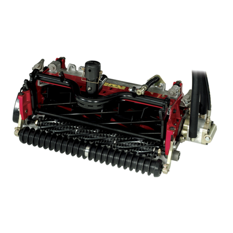
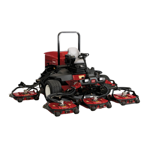
Toro Greensmaster 04251 User manual

FormNo.3385-370RevC
11and14-BladeCuttingUnit
Greensmaster®Flex™/eFlex®1800/2100
TractionUnits
ModelNo.04251—SerialNo.314001001andUp
ModelNo.04252—SerialNo.314001001andUp
ModelNo.04253—SerialNo.314001001andUp
ModelNo.04254—SerialNo.314001001andUp
Registeratwww.Toro.com.
OriginalInstructions(EN)*3385-370*C

WARNING
CALIFORNIA
Proposition65Warning
Thisproductcontainsachemical
orchemicalsknowntotheStateof
Californiatocausecancer,birthdefects,
orreproductiveharm.
Introduction
Readthisinformationcarefullytolearnhowtooperate
andmaintainyourproductproperlyandtoavoid
injuryandproductdamage.Youareresponsiblefor
operatingtheproductproperlyandsafely.
YoumaycontactT orodirectlyatwww.Toro.com
forproductsafetyandoperationtrainingmaterials,
accessoryinformation,helpndingadealer,orto
registeryourproduct.
Wheneveryouneedservice,genuineToroparts,or
additionalinformation,contactanAuthorizedService
DealerorT oroCustomerServiceandhavethemodel
andserialnumbersofyourproductready.Figure1
identiesthelocationofthemodelandserialnumbers
ontheproduct.Writethenumbersinthespace
provided.
g016942
Figure1
1.Locationofthemodelandserialnumbers
ModelNo.
SerialNo.
Thismanualidentiespotentialhazardsandhas
safetymessagesidentiedbythesafety-alertsymbol
(Figure2),whichsignalsahazardthatmaycause
seriousinjuryordeathifyoudonotfollowthe
recommendedprecautions.
g000502
Figure2
1.Safetyalertsymbol
Thismanualuses2wordstohighlightinformation.
Importantcallsattentiontospecialmechanical
informationandNoteemphasizesgeneralinformation
worthyofspecialattention.
Contents
Safety.......................................................................3
SafetyandInstructionalDecals..........................3
Setup........................................................................4
1InstallingtheFrontRoller.................................4
2UsingtheCutting-UnitProp..............................4
3AdjustingtheBedknifetotheReel....................4
4AdjustingtheRearRoller.................................6
5AdjustingtheHeightofCut...............................7
6AdjustingtheCut-offBar..................................8
7PreparingtheCuttingUnitforUseonan
eFlexMachine................................................9
ProductOverview....................................................11
Specications...................................................11
Attachments/Accessories..................................11
Operation................................................................12
AdjustingtheCuttingUnitDaily.........................12
AdjustingtheClipSetting..................................12
Maintenance...........................................................14
ServicingtheBedbar........................................14
BacklappingtheReel........................................15
©2017—TheToro®Company
8111LyndaleAvenueSouth
Bloomington,MN554202
Contactusatwww.Toro.com.
PrintedintheUSA
AllRightsReserved

Safety
Hazardcontrolandaccidentpreventionare
dependentupontheawareness,concern,and
propertrainingofthepersonnelinvolvedinthe
operation,transport,maintenance,andstorageof
themachine.Improperuseormaintenanceofthe
machinecanresultininjuryordeath.Toreduce
thepotentialforinjuryordeath,complywiththe
followingsafetyinstructions.
•Read,understand,andfollowallinstructionsinthe
tractionunitandcuttingunitoperator’smanuals
beforeoperatingthecuttingunit.
•Keepchildrenoutoftheoperatingarea.Never
allowchildrentooperatethemachine.
•Neveroperatethecuttingunitswhileill,tired,or
undertheinuenceofdrugsoralcohol.
•Donotoperatethemachinewithoutallguards
andothersafetyprotectivedevicesinplaceand
workingonthemachine.
•Wearappropriateclothing,includingeye
protection,slipresistant,substantialfootwear,and
hearingprotection.Tiebacklonghairanddonot
wearjewelry.
•Removealldebrisorotherobjectsthatthe
cutting-unitbladesmightpickupandthrow.Keep
allbystandersawayfromtheworkingarea.
•Ifthecuttingbladesstrikeasolidobjectortheunit
vibratesabnormally,stopandshutofftheengine.
Checkthecuttingunitfordamagedparts.Repair
anydamagebeforestartingthecuttingunit.
•Keepallnuts,bolts,andscrewstighttobesure
theequipmentisinsafeworkingcondition.
•Removethekeyfromignitionswitchtoprevent
accidentalstartingoftheenginewhenservicing,
adjusting,orstoringthemachine.
•Ifmajorrepairsareeverneededorifassistanceis
desired,contactanauthorizedTorodistributor.
•Toensureoptimumperformanceandcontinued
safetycerticationofthemachine,useonly
genuineTororeplacementpartsandaccessories.
Replacementpartsandaccessoriesmadeby
othermanufacturerscouldbedangerous,and
suchusecouldvoidtheproductwarranty.
SafetyandInstructionalDecals
Safetydecalsandinstructionsareeasilyvisibletotheoperatorandarelocatednearanyarea
ofpotentialdanger.Replaceanydecalthatisdamagedormissing.
decal104-7729
104–7729
1.Warning—readthe
instructionsbefore
servicingorperforming
maintenance.
2.Cutting/dismemberment
hazard;handorfoot—stop
theengineandwaitfor
movingpartstostop.
decal120-9570
120-9570
1.Warning—stayawayfrommovingparts,keepallguards
andshieldsinplace.
decal131-1820
131-1820
1.Cuttingunitclipchart
3

Setup
MediaandAdditionalParts
DescriptionQty.Use
Operator'sManual1Readthisbeforeinstallingandoperatingcuttingunit.
Partscatalog1Usethistoreferencepartnumbers.
Certicationofcompliance1Savethisforfuturereference.
Targetplate1
Weightbar1InstallthesepartsifyouareusinganeFlextractionunit.
1
InstallingtheFrontRoller
NoPartsRequired
Procedure
Thecuttingunitisshippedwithoutafrontroller.
Installtherollerusingtheloosepartssuppliedwith
thecuttingunitandinstallationinstructionsincluded
withtheroller.
2
UsingtheCutting-UnitProp
NoPartsRequired
Procedure
Wheneveryoutipthecuttingunittoexposethe
bedknife/reel,propuptherearofthecuttingunit
toensurethatthenutsonthebackendofthe
bedbar-adjustingscrewsarenotrestingonthework
surface(Figure3).
g016943
Figure3
1.Prop(notprovided)2.Bedknife-adjustingscrew
nut(2)
3
AdjustingtheBedknifeto
theReel
NoPartsRequired
Procedure
Note:Usethisprocedureaftergrinding,backlapping,
ordisassemblingthereelThisisnotadaily
adjustment.
Note:ForeFlexcuttingunits,thereel-to-bedknife
contacthassignicantimpactonenergyconsumption.
Verylightcontactisrecommendedforoptimumcutting
performanceandminimumbatteryconsumption.
1.Positionthecuttingunitonaat,levelwork
surface.
2.Tipthecuttingunittoexposethebedknifeand
reel.
4

Note:Ensurethatthenutsorbackofthe
bedbaradjustingscrewsarenotrestingonthe
worksurface(Figure3).
3.Rotatethereelsothat1ofthebladescrosses
thebedknifeedgebetweentherstandsecond
bedknifescrewheadslocatedontherightside
ofthecuttingunit.
4.Makeandidentifyingmarkonthebladewhereit
crossesthebedknifeedge.
Note:Thiswillmakelateradjustmentseasier.
5.Inserta0.05mm(0.002inch)shimbetweenthe
bladeandthebedknifeedgeatthepointmarked
instep4.
6.Turntherightbedbaradjustingscrew(Figure4)
untilyoufeellightpressureontheshimwhen
slidingitside-to-side.Removetheshim.
g014595
Figure4
1.Bedbar-adjustingscrew
7.Fortheleftsideofthecuttingunit,slowlyrotate
thereelsothattheclosestbladecrossesthe
bedknifeedgebetweentherstandsecond
screwheads.
8.Repeatsteps4through6fortheleftsideofthe
cuttingunitandleftbedbaradjustingscrew.
9.Repeatsteps5and6untilthereislightpressure
atthecontactpointsonboththeleftandright
sidesofthecuttingunit.
10.Toobtainlightcontactbetweenthereeland
bedknife,turneachbedbaradjustingscrew
clockwise3click.
Note:Eachclickonthebedbaradjustingscrew
movesthebedknife0.018mm(0.0007inch).Do
notovertightentheadjustingscrews.
Turningtheadjustingscrewclockwisemoves
thebedknifeedgeclosertothereel.Turningthe
adjustingscrewcounterclockwisemovesthe
bedknifeedgeawayfromthereel.
11.Testthecuttingperformancebyinsertingalong
stripofcuttingperformancepaperbetweenthe
reelandbedknife,perpendiculartothereel
andbedknife(Figure5).Slowlyrotatethereel
forwardtocutthepaper.
g014411
Figure5
5

4
AdjustingtheRearRoller
NoPartsRequired
Procedure
Dependingonyourdesiredheight-of-cutrangeyou
needtoadjusttherearrollerbrackets(Figure6or
Figure7)totheloworhighposition:
•Positionthespacerabovethesideplatemounting
ange(factorysetting)whentheheight-of-cut
settingsrangefrom1.5mmto6mm(1/16inchto
1/4inch)asshowninFigure6.
g014404
Figure6
1.Spacer3.Rollerbracket
2.Sideplatemountingange
•Positionthespacerbelowthesideplatemounting
angewhentheheightofcutsettingsrangefrom
3mmto25mm(1/8inchto1inch)asshownin
Figure7.
g014405
Figure7
1.Sideplatemountingange3.Rollerbracket
2.Spacer
1.Raisetherearofthecuttingunitandplacea
blockunderthebedknife.
2.Removethe2nutssecuringeachrollerbracket
andspacertoeachsideplatemountingange.
3.Lowertherollerandscrewsfromthesideplate
mountingangesandspacers.
4.Placethespacersontothescrewsaboveof
belowtherollerbrackets,asrequired(Figure6
orFigure7).
5.Securetherollerbracketandspacerstothe
undersideofthemountingangeswiththenuts
previouslyremoved.
6.Verifythatthebedknifetoreelcontactiscorrect.
Tipthemachinetoexposethefrontandrear
rollersandthebedknife.
Note:Thepositionoftherearrollertothereel
iscontrolledbythemachiningtolerancesof
theassembledcomponentsandparallelingis
notrequired.Alimitedamountofadjustmentis
possiblebysettingthecuttingunitonasurface
plateandlooseningthesideplatemounting
bolts(Figure8).Adjustandtightenboltswhen
nished.
g016944
Figure8
1.Sideplatemountingbolts
Important:Wheneverthecuttingunithas
tobetippedtoexposebedknife/reel,prop
uprearofcuttingunittoensurenutsonthe
backendofbedbaradjustingscrewsarenot
restingontheworksurface(Figure3).
6

5
AdjustingtheHeightofCut
NoPartsRequired
Procedure
Note:Thiscuttingunitcomesstandardwiththe
EdgemaxMicro-cutbedknifeandstandardbedbar.
Theeffectiveheightofcutisdependentonprevious
mowercongurationsandturfconditions(i.e.,roller
type,bedknifebehindcenterdistance,softorrm
greens,seasonconditions).Setinitialheight-of-cutto
0.25mmto0.38mm(0.010to0.015inch)higherthan
previoussetupandadjusttomatchconditions.
Note:Forheightsofcutgreaterthan13mm(0.500
inch),installthehighheight-of-cutkit.
Note:Usethefollowingcharttodeterminewhich
bedknifeisbestsuitedforthedesiredheightofcut.
RecommendedBedknife/HeightofCutChart
BedknifePartNumberHeightofCut
Edgemax
Micro-cut
(Standard)
115-1880(2100)
117-1530(1800)
1.5–4.7mm
(0.062–0.188inch)
Edgemax
Tournament
(Optional)
115-1881(2100)
117-1532(1800)
3.1–12.7mm
(0.125–0.500inch)
Micro-cut
(Optional)
93-4262(2100)
98-7261(1800)
1.5–4.7mm
(0.062–0.188inch)
Tournament
(Optional)
93-4263(2100)
98-7260(1800)
3.1–12.7mm
(0.125–0.500inch)
Extended
Micro-cut
(Optional)
108-4303(2100)
110-2300(1800)
1.5–4.7mm
(0.062–0.188inch)
Extended
Tournament
(Optional)
108-4302(2100)3.1–12.7mm
(0.125–0.500inch)
Low-cut
(Optional)
93-4264(2100)
110-2301(1800)
4.7–25.4mm
(0.188–1.00inch)
1.Loosenthelocknutssecuringtheheight-of-cut
armstothecuttingunitsideplates(Figure9).
g014407
Figure9
1.Height-of-cutarm3.Adjustingscrew
2.Locknut
2.Loosenthenutonthegaugebarandsetthe
adjustingscrewtothedesiredheightofcut
(Figure10).
Note:Thedistancebetweenthebottomofthe
screwheadandthefaceofbaristheheightof
cut.
g000489
Figure10
1.Gaugebar3.Nut
2.Heightadjustingscrew
3.Hookthescrewheadontothecuttingedgeof
thebedknifeandresttherearendofthebar
ontotherearoftheroller(Figure11).
7

g016945
Figure11
1.Gaugebar
4.Rotatetheadjustingscrewuntiltheroller
contactsthefrontofthegaugebar.
5.Adjustbothendsoftherolleruntiltheentire
rollerisparalleltothebedknife.
Important:Whensetproperly,therearand
frontrollerscontactthegaugebarandthe
screwissnugagainstthebedknife.This
ensuresthattheheight-of-cutisidenticalat
bothendsofthebedknife.
6.Tightenthenutstosecuretheadjustment
enoughtoremovetheplayfromthewasher.
6
AdjustingtheCut-offBar
NoPartsRequired
Procedure
Adjustthecut-offbartoensurethattheclippingsare
cleanlydischargedfromthereelareaasfollows.
1.Loosenthescrewssecuringthetopbar(Figure
12)tothecuttingunit.
g014643
Figure12
1.Cut-offbar
2.Inserta1.5mm(0.060inch)feelergauge
betweenthetopofthereelandthebarand
tightenthescrews.
Important:Ensurethatthebarandreelare
equaldistanceapartacrossthecomplete
reel.
Note:Youcanadjustthebartocompensatefor
changesinturfconditions.Adjustthebarshould
closertothereelwhentheturfisextremelydry.
Bycontrast,adjustthebarfurtherawayfromthe
reelwhentheturfconditionsarewet.Thebar
shouldbeparalleltothereeltoensureoptimum
performance,andyoushouldbeadjustit
wheneveryousharpenthereelonareelgrinder.
8

7
PreparingtheCuttingUnit
forUseonaneFlexMachine
Partsneededforthisprocedure:
1Targetplate
1Weightrod(suppliedwithyourtractionunit)
1Flange-headbolt(suppliedwithyourtractionunit)
InstallingtheTargetPlate
•IfyouwillbeusingthecuttingunitonaneFlex
tractionunit,installtheprovidedtargetplate,then
adjustthemachinesensorsasdescribedinthe
eFlextractionunitOperator’sManual.
•Ifyouwillbeusingthecuttinguniton
gasoline-poweredmachines,youdonotneedthe
targetplate.
•Ifyouwillbeusingthecuttingunitonbothgasoline
unitsandtheeFlexmachines,youcaninstallthe
targetplateandleaveitinstalledregardlessof
whichmachineyouuseiton.
1.Setupandpreparethecuttingunitasdescribed
inthecuttingunitOperator’sManual.
2.Removethecenter,grass-shieldbolt(Figure
13).
3.Installthetargetplatetothetopofthecutting
unit(undertheplasticcowling)usingthebolt
youremovedpreviously(Figure13).
g017294
Figure13
1.Center,grass-shieldbolt2.Targetplate
InstallingtheWeightRod
1.Enlargethelowerholeontherightsideofthe
cuttingunitusinga9mm(23/64inch)drillbit
(Figure14).
g026123
Figure14
2.LubricatetheO-ringontheweightrod.
3.InserttheO-ringendoftheweightrodintothe
previouslydrilledhole.
9

ProductOverview
Specications
TractorsThesecuttingunitsmountontheappropriatesizeFlexandeFlexTractionUnits.
Height-of-cutThecuttingheightisadjustedonthefrontrollerby2verticalscrewsandheldby2locking
capscrews
Height-of-cutrangeStandardbenchheightofcutrangeis1.6mm(0.062inch)to12.7mm(0.500inch).The
benchheight-of-cutrangewiththeHighHeightofCutKitinstalledis7mm(0.285inch)to25
mm(1.00inch).EffectiveHOCmayvarydependingonturfconditions,typeofbedknife,
rollersandattachmentsinstalled.
ReelbearingsThereare2sealedstainlesssteel,deepgrooveballbearings.
RollersThefrontrolleris6.3cm(2.5inches)indiameterwithavarietyofcongurationsselectedby
thecustomer.Therearrollerisa5.1cm(2inch)diameteraluminumfullroller.
BedknifeThereplaceablesingleedged,high-carbonsteelbedknifeisfastenedtoamachinedcast
ironbedbarwith13screws(2100)or11screws(1800).
BedknifeadjustmentThereisadualscrewadjustmenttothereel;detentscorrespondingto0.018mm(0.0007
inch)bedknifemovementforeachindexedposition.
GrassshieldThenon-adjustableshieldwithadjustablecut-offbarimprovesgrassdischargefromthe
reelinwetconditions.
CounterweightAcastironweightmountedoppositetothedrivelinebalancesthecuttingunit.
NetWeight,2100(withoutfrontroller)11-Blade—32.2kg(71lb);14-Blade—33.5kg(74lb)
NetWeight,1800(withoutfrontroller)11-Blade—30.8kg(68lb);14-Blade—32.2kg(71lb)
Attachments/Accessories
AselectionofT oroapprovedattachmentsandaccessoriesisavailableforusewiththemachinetoenhance
andexpanditscapabilities.ContactyourAuthorizedServiceDealerorDistributororgotowww.T oro.comfora
listofallapprovedattachmentsandaccessories.
11

Operation
Note:Determinetheleftandrightsidesofthe
machinefromthenormaloperatingposition.
Thedualpointbedknife-to-reeladjustmentsystem
incorporatedinthiscuttingunitsimpliesthe
adjustmentprocedureneededtodeliveroptimum
mowingperformance.Thepreciseadjustment
possiblewiththedualpoint/bedbardesigngives
thenecessarycontroltoprovideacontinual
self-sharpeningaction-thusmaintainingsharpcutting
edges,ensuringgoodquality-of-cut,andgreatly
reducingtheneedforroutinebacklapping.
AdjustingtheCuttingUnit
Daily
Priortomowingeachday,orasrequired,checkeach
cuttingunittoverifyproperbedknife-to-reelcontact.
Youmustrerformthisprocedureeventhoughthe
qualityofcutisacceptable.
1.Lowerthecuttingunitsontoahardsurface,shut
offtheengine,andremovetheignitionkey.
2.Shutoffthemachineasfollows:
•Gasolineunits:Shutofftheengineand
disconnectthespark-plugwire.
•Electricunits:Turnoffthemachineand
disconnectthebatteryconnector(T-handle).
3.Slowlyrotatethereelinareversedirection,
listeningforreel-to-bedknifecontact.Ifno
contactisevident,turnthebedknifeadjusting
knobsclockwise,1clickatatime,untilyoufeel
andhearlightcontact.
Note:Theadjustmentknobshavedetents
correspondingto0.018mm(0.0007inch)
bedknifemovementforeachindexedposition.
4.Ifyoufeelexcessivecontact,turnthebedknife
adjustingknobscounterclockwise,1clickat
atimeuntilnocontactisevident.Thenturn
thebedknifeadjustingknobs1clickatatime
clockwise,untilyoufeellightcontact.
Important:Lightcontactispreferredat
alltimes.Iflightcontactisnotmaintained,
thebedknife/reeledgeswillnotsufciently
self-sharpenanddullcuttingedgeswill
resultafteraperiodofoperation.Ifexcessive
contactismaintained,bedknife/reelwearwill
beaccelerated,unevenwearcanresult,and
qualityofcutmaybeadverselyaffected.
Note:ForeFlexcuttingunits,the
reel-to-bedknifecontacthasasignicant
impactonenergyconsumption.Verylight
contactisrecommendedforoptimumcutting
performanceandbatteryconsumption.
Note:Asthereelbladescontinuetorunagainst
thebedknife,aslightburrwillappearonthe
frontcuttingedgesurfacealongthefulllength
ofthebedknife.Ifyouoccasionallyrunale
acrossthefrontedgetoremovethisburr,this
willimprovethecuttingperformance.
Afterextendedrunning,aridgewilleventually
developatbothendsofthebedknife.Round
offthesenotchesorlethemushwiththe
cuttingedgeofthebedknifetoensuresmooth
operation.
AdjustingtheClipSetting
Thereare6clipsettingsonthecuttingunitthatyou
cansettomatchyourturfconditions.Startoutsetting
thecliptomatchtheheightofcut,butshouldthentest
thecuttingunitandadjustthecliptoobtainthequality
ofcutthatyoudesire.
1.Shutoffthemachineasfollows:
•Gasolineunits:Shutofftheengineand
disconnectthespark-plugwire.
•Electricunits:Turnoffthemachineand
disconnectthebatteryconnector(T-handle).
2.Loosentheangeboltsecuringthebeltcover
andremovethebeltcovertoexposethebelt
(Figure16).
g016915
Figure16
1.Beltcover
3.Loosenthebearing-housingnut(Figure17).
12

g017116
Figure17
1.Bearing-housingnut3.Compressionspring
2.Reeldrivebelt
4.Usinga16mm(5/8inch)wrench,rotatethe
bearinghousingtomakesureitoperatesfreely.
5.Removethebelt(Figure17).
6.UsingthechartshownonthedecalinFigure18,
determinetheclipsettingyouwantandwhich
pulleysyouwillneedtomove.
Note:Eachpulleyisnumbered(22,24,and
25).Movethepulleystothepositionsindicated
inthechartforyourclipsetting.
decal131-1820
Figure18
7.Loosenthe2setscrewsoneachpulleyyou
needtomoveusingahexwrench.
8.Removeeachpulley.
9.Installeachpulleyinthenewcongurationas
indicatedonthedecal(Figure18).
Note:Ensurethatthesetscrewsoneachpulley
arepositionedtoalignwiththekeyandatarea
ontheshaft.
10.Torquethesetscrewsto8.3to8.9N-m(74to
79in-lb).
11.Installthebelt.
12.Ensurethatthecompressionspringisapplying
tensiontothebelt(Figure17).
13.Tightenthebearing-housingnut.
14.Installthebeltcover.
13

Maintenance
Note:Determinetheleftandrightsidesofthe
machinefromthenormaloperatingposition.
ServicingtheBedbar
RemovingtheBedbar
1.Turnthebedbar-adjustingscrew,
counterclockwise,tobackthebedknife
awayfromthereel(Figure19).
g014641
Figure19
1.Bedbar-adjustingscrew3.Bedbar
2.Spring-tensionnut4.Washer
2.Backoutthespring-tensionnutuntilthewasher
isnolongertensionedagainstthebedbar
(Figure19).
3.Oneachsideofthemachine,loosenthelocknut
securingthebedbarbolt(Figure20).
g014409
Figure20
1.Bedbarbolt2.Locknut
4.Removeeachbedbarboltallowingthebedbar
tobepulleddownwardandremovedfromthe
machinebolt(Figure20).
Accountforthe2nylonand2stampedsteel
washersoneachendofthebedbar(Figure21).
g016970
Figure21
1.Bedbarbolt3.Steelwasher
2.Nut4.Nylonwasher
AssemblingtheBedbar
1.Installthebedbar,positioningthemountingears
betweenthewasherandbedbaradjuster.
2.Securethebedbartoeachsideplatewiththe
bedbarbolts(nutsonbolts)and4washers(8
total).
3.Positionanylonwasheroneachsideoftheside
plateboss.Placeasteelwasheroutsideeach
ofthenylonwashers(Figure21).
4.Torquethebedbarboltsto27to36N-m(240
to320inch-lb).Tightenthelocknutsbyhand
untiltheoutsidesteelwasherstopsrotatingand
thereisnoendplay.Thewashersontheinside
mayhaveagap.
Important:Donotovertightenthelocknuts
ortheywilldeectthesideplates.
5.Tightenthespringtensionnutuntilthespringis
collapsed,thenbackitoff1/2turn(Figure22).
14

g014642
Figure22
1.Springtensionnut2.Spring
BacklappingtheReel
DANGER
Contactwiththereelorothermovingparts
canresultinpersonalinjury.
Keepyourngers,hands,andclothingaway
fromthereelsorothermovingparts.
•Stayawayfromthereelwhilebacklapping.
•Neveruseashorthandledpaintbrushfor
backlapping.Handleassemblypartsare
availablefromyourlocalauthorizedToro
distributor.
Youcanbacklapthereelseitherbyleavingthecutting
unitonthetractionunitorremovingthecuttingunit
completelyfromthetractionunit.Ifthecuttingunitis
leftonthetractionunit,movethehexcouplerbetween
themaindriveandcuttingunitdrivetothedecoupled
positiontopreventexcessiveweartothereelbrake.
1.Positionthemachineonaclean,levelsurface.
2.Shutoffthemachineasfollows:
•Gasolineunits:shutofftheengineand
disconnectthespark-plugwire.
•Electricunits:turnoffthemachineand
disconnectthebatteryconnector(T-handle).
3.Engagetheparkingbrake.
4.Connectthebacklappingmachinetothecutting
unitbyconnectinga1/2inchhexsockettothe
reelpulleyoutputshaftontheleftsideofthe
cuttingunit.
Note:Additionalinstructionsandprocedures
onBacklappingareavailableintheToro
SharpeningReelandRotaryMowersManual
(FormNo.80-300PT).
Note:Forabettercuttingedge,runale
acrossthefrontfaceofthebedknifewhenthe
lappingoperationiscompleted.Thisremoves
anyburrsorroughedgesthatmayhavebuiltup
onthecuttingedge.Averylightletouchmay
benecessaryonthetopedgetobreaktheburr
offcompletelyfromthecuttingedge.
Note:Ifthecuttingunitwasleftattachedto
themachineduringbacklapping,couplethehex
shaftofthemachinebacktothecuttingunit.
15

Notes:

Notes:

Notes:

DeclarationofIncorporation
TheT oroCompany,8111LyndaleAve.South,Bloomington,MN,USAdeclaresthatthefollowingunit(s)
conform(s)tothedirectiveslisted,wheninstalledinaccordancewiththeaccompanyinginstructionsontocertain
ToromodelsasindicatedontherelevantDeclarationsofConformity.
ModelNo.SerialNo.ProductDescriptionInvoiceDescriptionGeneralDescriptionDirective
04251314000001andUp
11-BladeCuttingUnit,
GreensmasterFlex/eFlex
2100TractionUnit
11BLADE-FLEX2100LawnMower2006/42/EC
04252314000001andUp
14-BladeCuttingUnit,
GreensmasterFlex/eFlex
2100TractionUnit
14BLADE-FLEX2100LawnMower2006/42/EC
04253314000001andUp
11-BladeCuttingUnit,
GreensmasterFlex/eFlex
1800TractionUnit
11BLADE-FLEX1800LawnMower2006/42/EC
04254314000001andUp
14-BladeCuttingUnit,
GreensmasterFlex/eFlex
1800TractionUnit
14BLADE-FLEX1800LawnMower2006/42/EC
RelevanttechnicaldocumentationhasbeencompiledasrequiredperPartBofAnnexVIIof2006/42/EC.
Wewillundertaketotransmit,inresponsetorequestsbynationalauthorities,relevantinformationonthispartly
completedmachinery.Themethodoftransmissionshallbeelectronictransmittal.
ThismachineryshallnotbeputintoserviceuntilincorporatedintoapprovedT oromodelsasindicatedonthe
associatedDeclarationofConformityandinaccordancewithallinstructions,wherebyitcanbedeclaredin
conformitywithallrelevantDirectives.
Certied:AuthorizedRepresentative:
MarcelDutrieux
ManagerEuropeanProductIntegrity
ToroEuropeNV
Nijverheidsstraat5
2260Oevel
Belgium
DavidKlis
Sr.EngineeringManagerTel.+3216386659
8111LyndaleAve.South
Bloomington,MN55420,USA
December18,2013

TheToroTotalCoverageGuarantee
ALimitedWarranty
ConditionsandProductsCovered
TheToroCompanyanditsafliate,ToroWarrantyCompany,pursuant
toanagreementbetweenthem,jointlywarrantyourToroCommercial
product(“Product”)tobefreefromdefectsinmaterialsorworkmanship
fortwoyearsor1500operationalhours*,whicheveroccursrst.This
warrantyisapplicabletoallproductswiththeexceptionofAerators
(refertoseparatewarrantystatementsfortheseproducts).Wherea
warrantableconditionexists,wewillrepairtheProductatnocosttoyou
includingdiagnostics,labor,parts,andtransportation.Thiswarranty
beginsonthedatetheProductisdeliveredtotheoriginalretailpurchaser.
*Productequippedwithanhourmeter.
InstructionsforObtainingWarrantyService
YouareresponsiblefornotifyingtheCommercialProductsDistributoror
AuthorizedCommercialProductsDealerfromwhomyoupurchasedthe
Productassoonasyoubelieveawarrantableconditionexists.Ifyouneed
helplocatingaCommercialProductsDistributororAuthorizedDealer,or
ifyouhavequestionsregardingyourwarrantyrightsorresponsibilities,
youmaycontactusat:
ToroCommercialProductsServiceDepartment
ToroWarrantyCompany
8111LyndaleAvenueSouth
Bloomington,MN55420-1196
952–888–8801or800–952–2740
E-mail:[email protected]
OwnerResponsibilities
AstheProductowner,youareresponsibleforrequiredmaintenanceand
adjustmentsstatedinyourOperator'sManual.Failuretoperformrequired
maintenanceandadjustmentscanbegroundsfordisallowingawarranty
claim.
ItemsandConditionsNotCovered
Notallproductfailuresormalfunctionsthatoccurduringthewarranty
periodaredefectsinmaterialsorworkmanship.Thiswarrantydoesnot
coverthefollowing:
•Productfailureswhichresultfromtheuseofnon-T ororeplacement
parts,orfrominstallationanduseofadd-on,ormodiednon-T oro
brandedaccessoriesandproducts.Aseparatewarrantymaybe
providedbythemanufactureroftheseitems.
•Productfailureswhichresultfromfailuretoperformrecommended
maintenanceand/oradjustments.Failuretoproperlymaintainyour
ToroproductpertheRecommendedMaintenancelistedinthe
Operator’sManualcanresultinclaimsforwarrantybeingdenied.
•ProductfailureswhichresultfromoperatingtheProductinanabusive,
negligent,orrecklessmanner.
•Partssubjecttoconsumptionthroughuseunlessfoundtobedefective.
Examplesofpartswhichareconsumed,orusedup,duringnormal
Productoperationinclude,butarenotlimitedto,brakepadsand
linings,clutchlinings,blades,reels,rollersandbearings(sealedor
greasable),bedknives,sparkplugs,castorwheelsandbearings,tires,
lters,belts,andcertainsprayercomponentssuchasdiaphragms,
nozzles,andcheckvalves,etc.
•Failurescausedbyoutsideinuence.Conditionsconsideredtobe
outsideinuenceinclude,butarenotlimitedto,weather,storage
practices,contamination,useofunapprovedfuels,coolants,lubricants,
additives,fertilizers,water,orchemicals,etc.
•Failureorperformanceissuesduetotheuseoffuels(e.g.gasoline,
diesel,orbiodiesel)thatdonotconformtotheirrespectiveindustry
standards.
•Normalnoise,vibration,wearandtear,anddeterioration.
•Normal“wearandtear”includes,butisnotlimitedto,damagetoseats
duetowearorabrasion,wornpaintedsurfaces,scratcheddecalsor
windows,etc.
Parts
Partsscheduledforreplacementasrequiredmaintenancearewarranted
fortheperiodoftimeuptothescheduledreplacementtimeforthatpart.
Partsreplacedunderthiswarrantyarecoveredforthedurationofthe
originalproductwarrantyandbecomethepropertyofT oro.Torowillmake
thenaldecisionwhethertorepairanyexistingpartorassemblyorreplace
it.Toromayuseremanufacturedpartsforwarrantyrepairs.
DeepCycleandLithium-IonBatteryWarranty:
DeepcycleandLithium-Ionbatterieshaveaspeciedtotalnumberof
kilowatt-hourstheycandeliverduringtheirlifetime.Operating,recharging,
andmaintenancetechniquescanextendorreducetotalbatterylife.Asthe
batteriesinthisproductareconsumed,theamountofusefulworkbetween
chargingintervalswillslowlydecreaseuntilthebatteryiscompletelyworn
out.Replacementofwornoutbatteries,duetonormalconsumption,
istheresponsibilityoftheproductowner.Batteryreplacementmaybe
requiredduringthenormalproductwarrantyperiodatowner’sexpense.
Note:(Lithium-Ionbatteryonly):ALithium-Ionbatteryhasapartonly
proratedwarrantybeginningyear3throughyear5basedonthetime
inserviceandkilowatthoursused.RefertotheOperator'sManualfor
additionalinformation.
MaintenanceisatOwner’sExpense
Enginetune-up,lubrication,cleaningandpolishing,replacementoflters,
coolant,andcompletingrecommendedmaintenancearesomeofthe
normalservicesToroproductsrequirethatareattheowner’sexpense.
GeneralConditions
RepairbyanAuthorizedToroDistributororDealerisyoursoleremedy
underthiswarranty.
NeitherTheToroCompanynorToroWarrantyCompanyisliablefor
indirect,incidentalorconsequentialdamagesinconnectionwiththe
useoftheToroProductscoveredbythiswarranty,includingany
costorexpenseofprovidingsubstituteequipmentorserviceduring
reasonableperiodsofmalfunctionornon-usependingcompletion
ofrepairsunderthiswarranty.ExceptfortheEmissionswarranty
referencedbelow,ifapplicable,thereisnootherexpresswarranty.All
impliedwarrantiesofmerchantabilityandtnessforusearelimitedto
thedurationofthisexpresswarranty.
Somestatesdonotallowexclusionsofincidentalorconsequential
damages,orlimitationsonhowlonganimpliedwarrantylasts,sotheabove
exclusionsandlimitationsmaynotapplytoyou.Thiswarrantygivesyou
speciclegalrights,andyoumayalsohaveotherrightswhichvaryfrom
statetostate.
Noteregardingenginewarranty:
TheEmissionsControlSystemonyourProductmaybecoveredby
aseparatewarrantymeetingrequirementsestablishedbytheU.S.
EnvironmentalProtectionAgency(EPA)and/ortheCaliforniaAirResources
Board(CARB).Thehourlimitationssetforthabovedonotapplytothe
EmissionsControlSystemWarranty.RefertotheEngineEmissionControl
WarrantyStatementsuppliedwithyourproductorcontainedintheengine
manufacturer’sdocumentationfordetails
CountriesOtherthantheUnitedStatesorCanada
CustomerswhohavepurchasedT oroproductsexportedfromtheUnitedStatesorCanadashouldcontacttheirToroDistributor(Dealer)toobtain
guaranteepoliciesforyourcountry,province,orstate.IfforanyreasonyouaredissatisedwithyourDistributor'sserviceorhavedifcultyobtaining
guaranteeinformation,contacttheToroimporter.374-0253RevB
This manual suits for next models
3
Table of contents
Other Toro Lawn Mower manuals

Toro
Toro 31970 User manual

Toro
Toro Z580-D Z Master 74266CP User manual

Toro
Toro 30140 User manual

Toro
Toro 74198 User manual

Toro
Toro Groundsmaster 30344 User manual

Toro
Toro TimeCutter ZS 4200S User manual

Toro
Toro E-Z Vac 79345 User manual

Toro
Toro Groundsmaster 4100-D User manual
Toro
Toro 3674 User manual

Toro
Toro Z Master 74925 User manual