Toro 30582 Groundsmaster 580-D User manual

Operator’s Manual
English (EN, GB)
Form No. 3354–124 Rev A
Groundsmaster)580-D
Traction and Cutting Units
Model No. 30582—260000001 and Up
Model No. 30583—260000001 and Up

2
All Rights Reserved
Printed in the USA
W2005 by The Toro Company
8111 Lyndale Avenue South
Bloomington, MN 55420-1196
CALIFORNIA
Proposition 65 Warning
Diesel engine exhaust and some of its constituents
are known to the State of California to cause
cancer, birth defects, and other reproductive harm.
Warning
Contents
Page
Introduction 3. . . . . . . . . . . . . . . . . . . . . . . . . . . . . . . .
Safety 3. . . . . . . . . . . . . . . . . . . . . . . . . . . . . . . . . . . . .
Safe Operating Practices 3. . . . . . . . . . . . . . . . . . . .
Toro Riding Mower Safety 5. . . . . . . . . . . . . . . . . .
Sound Pressure Level 6. . . . . . . . . . . . . . . . . . . . . .
Sound Power Level 6. . . . . . . . . . . . . . . . . . . . . . .
Vibration Level 6. . . . . . . . . . . . . . . . . . . . . . . . . . .
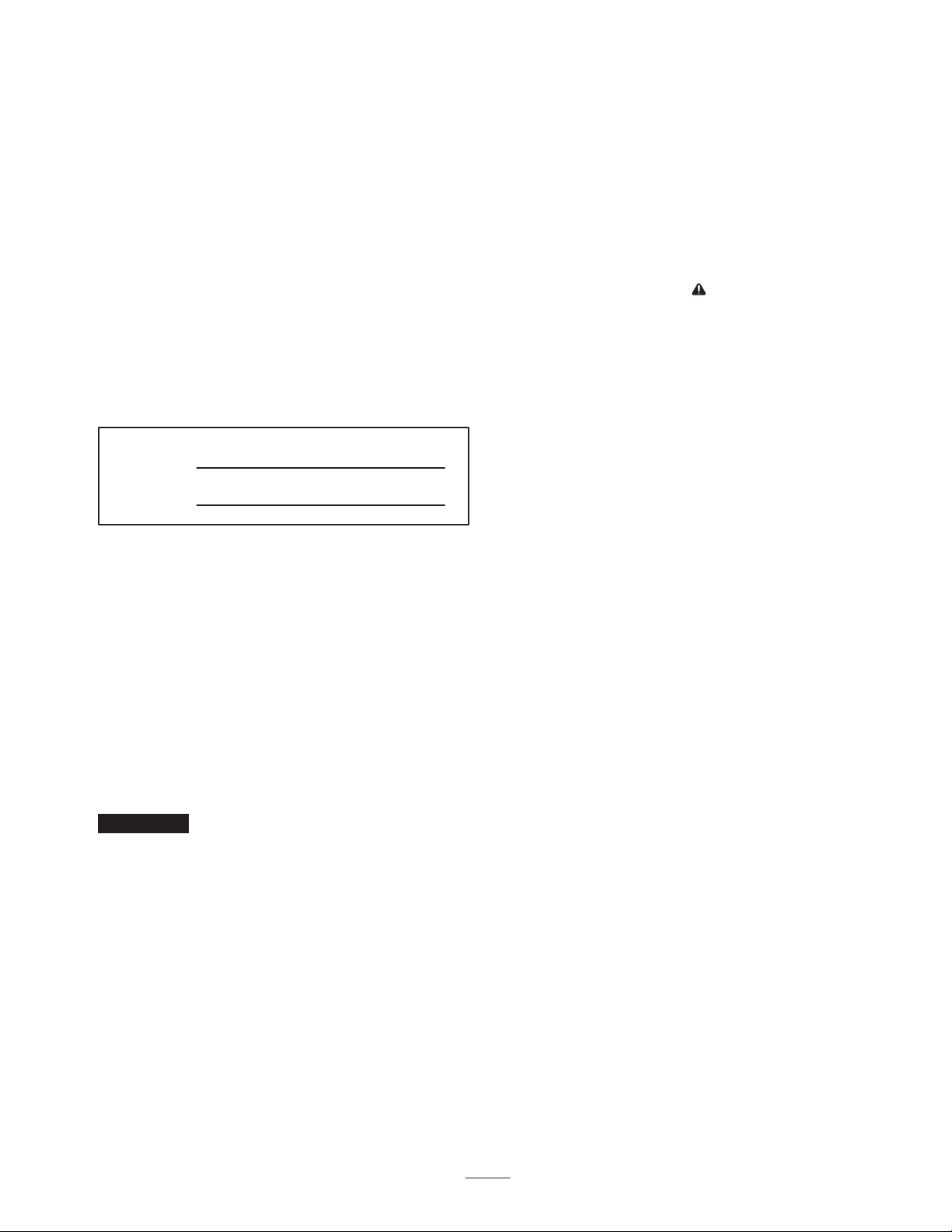
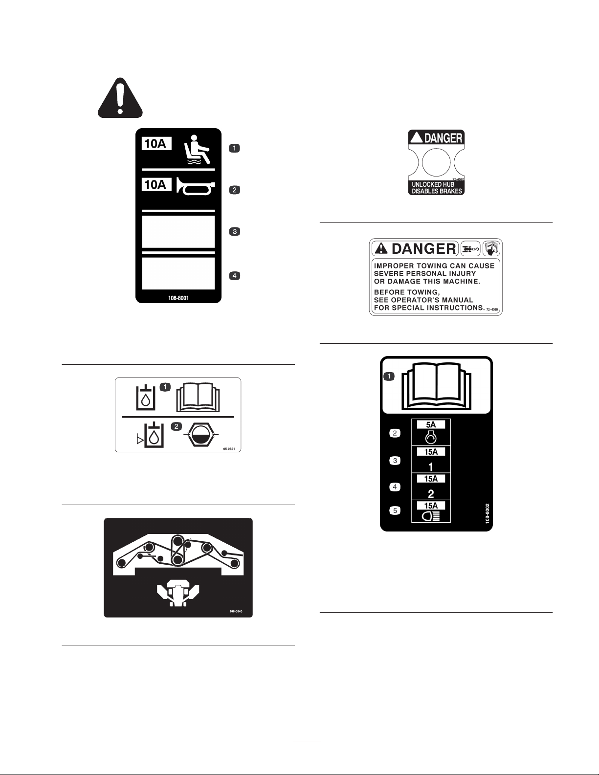
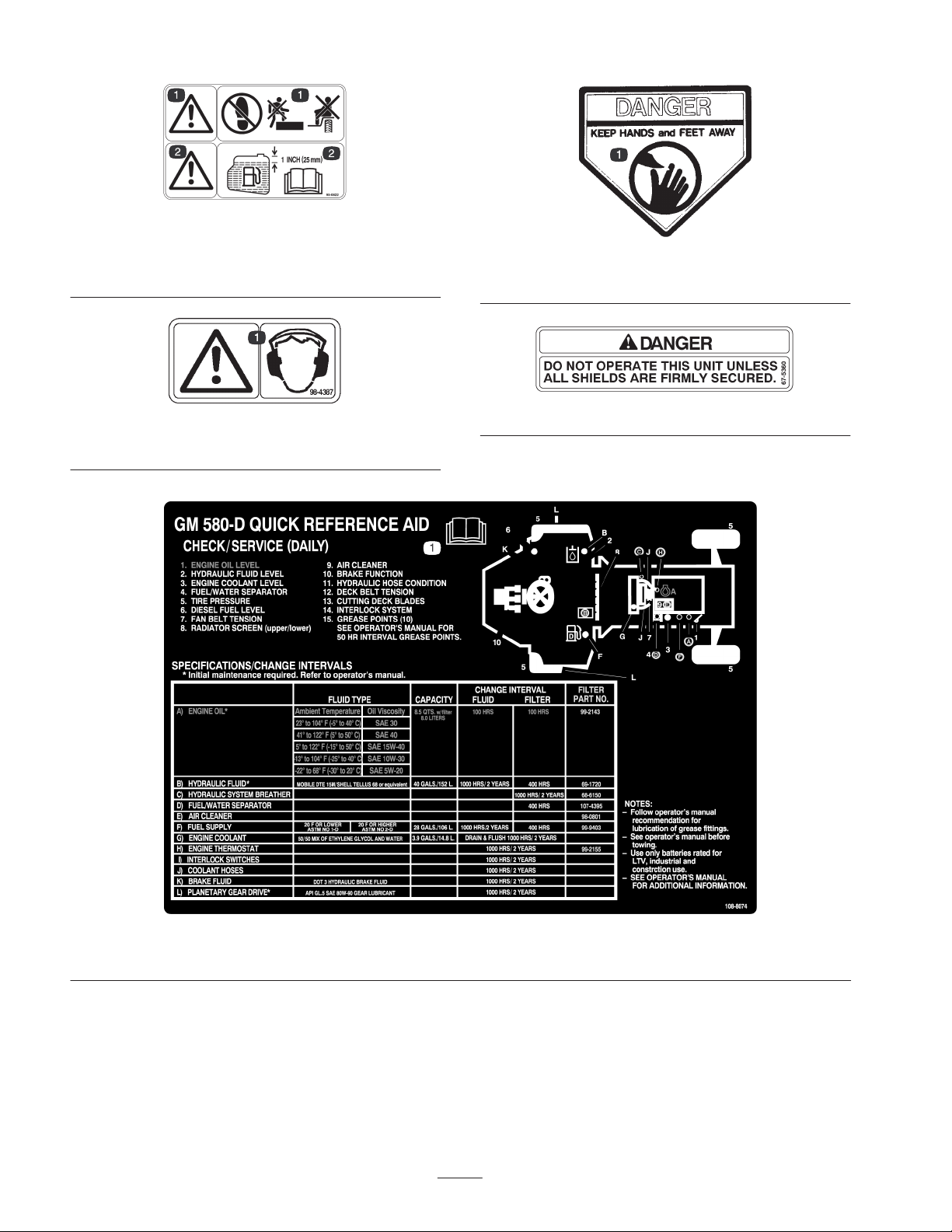
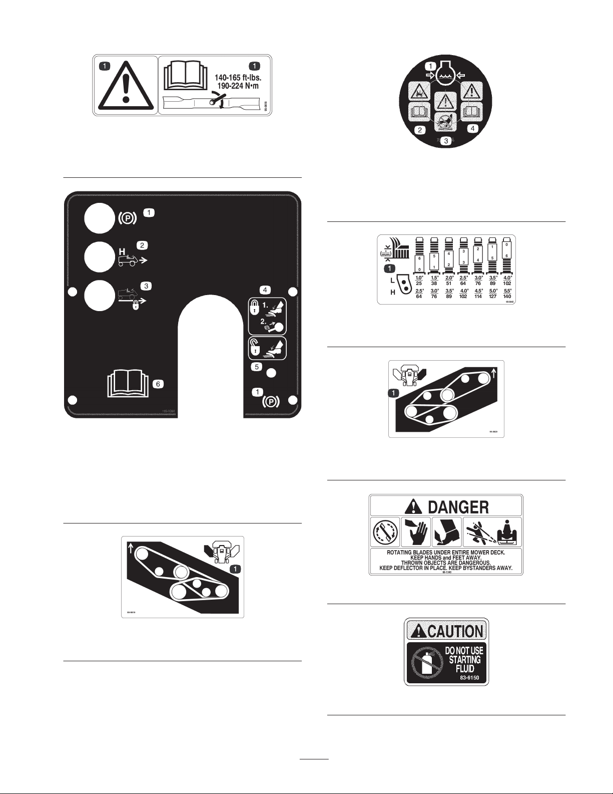
Safety and Instruction Decals 7. . . . . . . . . . . . . . . .
Specifications 13. . . . . . . . . . . . . . . . . . . . . . . . . . . . . . .
Traction Unit 13. . . . . . . . . . . . . . . . . . . . . . . . . . . .
All Cutting Units 14. . . . . . . . . . . . . . . . . . . . . . . . .
Triflex Cutting Unit (Front) 14. . . . . . . . . . . . . . . . .
Outboard Cutting Units 15. . . . . . . . . . . . . . . . . . . .
Dimensions 15. . . . . . . . . . . . . . . . . . . . . . . . . . . . .
Optional Equipment 15. . . . . . . . . . . . . . . . . . . . . . .
Setup 16. . . . . . . . . . . . . . . . . . . . . . . . . . . . . . . . . . . . .
Checking the Batteries 16. . . . . . . . . . . . . . . . . . . . .
Before Operating 18. . . . . . . . . . . . . . . . . . . . . . . . . . . .
Checking the Engine Oil 18. . . . . . . . . . . . . . . . . . .
Checking the Cooling System 19. . . . . . . . . . . . . . .
Checking the Hydraulic System Fluid 19. . . . . . . . .
Filling the Fuel Tank 20. . . . . . . . . . . . . . . . . . . . . .
Checking the Tire Pressure 20. . . . . . . . . . . . . . . . . .
Checking Systems Operation 20. . . . . . . . . . . . . . . .
Checking Cutting Unit Mismatch 20. . . . . . . . . . . . .
Adjusting the Height of Cut 21. . . . . . . . . . . . . . . . .
Adjusting the Skids 22. . . . . . . . . . . . . . . . . . . . . . .
Operation 23. . . . . . . . . . . . . . . . . . . . . . . . . . . . . . . . . .
Controls 23. . . . . . . . . . . . . . . . . . . . . . . . . . . . . . . .
Starting and Stopping the Engine 27. . . . . . . . . . . . .
Bleeding the Fuel System 28. . . . . . . . . . . . . . . . . . .
Diagnostic Light 28. . . . . . . . . . . . . . . . . . . . . . . . . .
Diagnostic ACE Display 29. . . . . . . . . . . . . . . . . . .
Checking the Interlock Switches 29. . . . . . . . . . . . .
Checking the Warning Indicator Lights 32. . . . . . . .
Pushing or Towing the Machine 32. . . . . . . . . . . . . .
Operating Characteristics 32. . . . . . . . . . . . . . . . . . .
Four Wheel Drive Operation 33. . . . . . . . . . . . . . . .
Maintenance 35. . . . . . . . . . . . . . . . . . . . . . . . . . . . . . . .
Recommended Maintenance Schedule 35. . . . . . . . .
Daily Maintenance Checklist 36. . . . . . . . . . . . . . . .
Service Interval Chart 37. . . . . . . . . . . . . . . . . . . . . .
Lubrication 38. . . . . . . . . . . . . . . . . . . . . . . . . . . . . .
Engine Oil and Filter 40. . . . . . . . . . . . . . . . . . . . . .
Engine Fuel System 41. . . . . . . . . . . . . . . . . . . . . . .
Engine Cooling System 42. . . . . . . . . . . . . . . . . . . .
General Air Cleaner Maintenance 43. . . . . . . . . . . .
Servicing the Air Cleaner 43. . . . . . . . . . . . . . . . . . .
Servicing the Hydraulic System 44. . . . . . . . . . . . . .
Servicing the Planetary Gear Drive 46. . . . . . . . . . .
Servicing the Battery 47. . . . . . . . . . . . . . . . . . . . . .
Fuses and Circuit Breaker 48. . . . . . . . . . . . . . . . . .
Servicing the Brake System 48. . . . . . . . . . . . . . . . .
Wheels and Tires 49. . . . . . . . . . . . . . . . . . . . . . . . .
Cutting Unit Lubrication 49. . . . . . . . . . . . . . . . . . .
Blade Maintenance 49. . . . . . . . . . . . . . . . . . . . . . . .
Blade Bolt Torque 50. . . . . . . . . . . . . . . . . . . . . . . . .
Checking for a Bent Blade 51. . . . . . . . . . . . . . . . . .
Removing the Cutting Unit Blade 51. . . . . . . . . . . .
Inspecting and Sharpening the Blade 51. . . . . . . . . .
Inspecting and Adjusting the Cutting Unit
Belt Tension 52. . . . . . . . . . . . . . . . . . . . . . . . . . .
Replacing the Blade Drive Belts 53. . . . . . . . . . . . .
Separating the Cutting Units from the
Traction Unit 55. . . . . . . . . . . . . . . . . . . . . . . . . . .
Checking and Correcting Cutting Blade Mismatch 55
Adjusting the Winglet Stabilizers 56. . . . . . . . . . . . .
Adjusting the Traction Control Rod 57. . . . . . . . . . .
Cylinder Head Bolts 57. . . . . . . . . . . . . . . . . . . . . . .
Engine Valve Clearance 57. . . . . . . . . . . . . . . . . . . .
Inspect and Adjust Fuel Injection Nozzles 57. . . . . .
Electrical Schematic – Model 30582 58. . . . . . . . . .
Electrical Schematic – Model 30583 59. . . . . . . . . .
Hydraulic Schematic – Model 30582 60. . . . . . . . . .
Hydraulic Schematic – Model 30583 61. . . . . . . . . .
The Toro General Commercial Products Warranty 64. .

3
Introduction
Read this manual carefully to learn how to operate and
maintain your product properly. The information in this
manual can help you and others avoid injury and product
damage. Although Toro designs and produces safe
products, you are responsible for operating the product
properly and safely.
Whenever you need service, genuine Toro parts, or
additional information, contact an Authorized Service
Dealer or Toro Customer Service and have the model and
serial numbers of your product ready. A plate with the
model and serial numbers is located on the left bulkhead
below the operator’s seat and on the rear channel of each
cutting unit.
Write the product model and serial numbers in the space
below:
Model No.
Serial No.
This manual identifies potential hazards and has special
safety messages that help you and others avoid personal
injury and even death. Danger, Warning, and Caution are
signal words used to identify the level of hazard. However,
regardless of the hazard, be extremely careful.
Danger signals an extreme hazard that will cause serious
injury or death if you do not follow the recommended
precautions.
Warning signals a hazard that may cause serious injury or
death if you do not follow the recommended precautions.
Caution signals a hazard that may cause minor or moderate
injury if you do not follow the recommended precautions.
This manual uses two other words to highlight information.
Important calls attention to special mechanical
information and Note: emphasizes general information
worthy of special attention.
Safety
This machine meets or exceeds CEN standard EN
836:1997 (when appropriate decals applied), and ANSI
B71.4-1999 specifications in effect at the time of
production when equipped with required weights as
listed in the weight chart.
Improper use or maintenance by the operator or owner
can result in injury. To reduce the potential for injury,
comply with these safety instructions and always pay
attention to the safety alert symbol, which means
CAUTION, WARNING, or DANGER—“personal
safety instruction.” Failure to comply with the
instruction may result in personal injury or death.
Safe Operating Practices
The following instructions are from the CEN standard EN
836:1997, ISO standard 5395:1990, and ANSI B71.4-1999.
Training
•Read the operator’s manual and other training material
carefully. Be familiar with the controls, safety signs,
and the proper use of the equipment.
•If the operator or mechanic can not read the language of
this manual, it is the owner’s responsibility to explain
this material to them.
•Never allow children or people unfamiliar with these
instructions to use or service the mower. Local
regulations may restrict the age of the operator.
•Never mow while people, especially children, or pets
are nearby.
•Keep in mind that the operator or user is responsible for
accidents or hazards occurring to other people or their
property.
•Do not carry passengers.
•All drivers and mechanics should seek and obtain
professional and practical instruction. The owner is
responsible for training the users. Such instruction
should emphasize:
– the need for care and concentration when working
with ride-on machines;
– control of a ride-on machine sliding on a slope will
not be regained by the application of the brake. The
main reasons for loss of control are:
•insufficient wheel grip;
•being driven too fast;
•inadequate braking;
•the type of machine is unsuitable for the task;

4
•lack of awareness of the effect of ground
conditions, especially slopes.
•The owner/user can prevent and is responsible for
accidents or injuries occurring to himself or herself,
other people, or property.
Preparation
•While mowing, always wear substantial footwear, long
trousers, hard hat, safety glasses, and hearing
protection. Long hair, loose clothing, or jewelry may
get tangled in moving parts. Do not operate the
equipment when barefoot or wearing open sandals.
•Thoroughly inspect the area where the equipment is to
be used and remove all objects which may be thrown by
the machine.
•Warning—Fuel is highly flammable. Take the
following precautions:
– Store fuel in containers specifically designed for this
purpose.
– Refuel outdoors only and do not smoke while
refueling.
– Add fuel before starting the engine. Never remove
the cap of the fuel tank or add fuel while the engine
is running or when the engine is hot.
– If fuel is spilled, do not attempt to start the engine
but move the machine away from the area of
spillage and avoid creating any source of ignition
until fuel vapors have dissipated.
– Replace all fuel tank and container caps securely.
•Replace faulty silencers/mufflers.
•Evaluate the terrain to determine what accessories and
attachments are needed to properly and safely perform
the job. Only use accessories and attachments approved
by the manufacturer.
•Check that operator’s presence controls, safety switches
and shields are attached and functioning properly. Do
not operate unless they are functioning properly.
Operation
•Do not operate the engine in a confined space where
dangerous carbon monoxide fumes can collect.
•Mow only in daylight or in good artificial light.
•Before attempting to start the engine, disengage all
blade attachment clutches, shift into neutral, and engage
the parking brake.
•Do not put hands or feet near or under rotating parts.
Keep clear of the discharge opening at all times.
•Remember there is no such thing as a safe slope. Travel
on grass slopes requires particular care. To guard
against overturning:
– do not stop or start suddenly when going up or
downhill;
– machine speeds should be kept low on slopes and
during tight turns;
– stay alert for humps and hollows and other hidden
hazards;
– never mow across the face of the slope, unless the
mower is designed for this purpose.
– Use counterweight(s) or wheel weights when
suggested in the operator’s manual.
•Stay alert for holes in the terrain and other hidden
hazards.
•Watch out for traffic when crossing or near roadways.
•Stop the blades from rotating before crossing surfaces
other than grass.
•When using any attachments, never direct discharge of
material toward bystanders nor allow anyone near the
machine while in operation.
•Never operate the machine with damaged guards,
shields, or without safety protective devices in place. Be
sure all interlocks are attached, adjusted properly, and
functioning properly.
•Do not change the engine governor settings or
overspeed the engine. Operating the engine at excessive
speed may increase the hazard of personal injury.
•Before leaving the operator’s position:
– stop on level ground;
– disengage the power take-off and lower the
attachments;
– change into neutral and set the parking brake;
– stop the engine and remove the key.
•Disengage drive to attachments when transporting or
not in use.
•Stop the engine and disengage drive to attachment
– before refuelling;
– before making height adjustment unless adjustment
can be made from the operator’s position.
– before clearing blockages;
– before checking, cleaning or working on the mower;

5
– after striking a foreign object or if an abnormal
vibration occurs. Inspect the mower for damage and
make repairs before restarting and operating the
equipment. Torque all the spindle pulley nuts to
130–150 ft–lbs.;
•Reduce the throttle setting before stopping the engine
and, if the engine is provided with a fuel shut-off valve,
turn the fuel off at the conclusion of mowing.
•Keep hands and feet away from the cutting units.
•Look behind and down before backing up to be sure of
a clear path.
•Slow down and use caution when making turns and
crossing roads and sidewalks. Stop blades from rotating.
•Be aware of the mower discharge direction and do not
point it at anyone.
•Do not operate the mower under the influence of
alcohol or drugs.
•Use care when loading or unloading the machine onto a
trailer or truck.
•Use care when approaching blind corners, shrubs, trees,
or other objects that may obscure vision.
Maintenance and Storage
•Keep all nuts, bolts and screws tight to be sure the
equipment is in safe working condition.
•Never store the equipment with fuel in the tank inside a
building where fumes may reach an open flame or
spark.
•Allow the engine to cool before storing in any
enclosure.
•To reduce the fire hazard, keep the engine,
silencer/muffler, battery compartment fuel storage area,
cutting units and drives free of grass, leaves, or
excessive grease. Clean up oil or fuel spillage.
•Keep all parts in good working condition and all
hardware and hydraulic fittings tightened. Replace all
worn or damaged parts and decals.
•If the fuel tank has to be drained, do this outdoors.
•Be careful during adjustment of the machine to prevent
entrapment of the fingers between moving blades and
fixed parts of the machine.
•On multi-spindle mowers, take care as rotating one
blade can cause other blades to rotate.
•Disengage drives, lower the cutting units, set parking
brake, stop engine and remove key. Wait for all
movement to stop before adjusting, cleaning or
repairing.
•Use jack stands to support components when required.
•Carefully release pressure from components with stored
energy.
•Disconnect battery before making any repairs.
Disconnect the negative terminal first and the positive
last. Reconnect positive first and negative last.
•Use care when checking the blades. Wear gloves and
use caution when servicing them.
•Keep hands and feet away from moving parts. If
possible, do not make adjustments with the engine
running.
•Charge batteries in an open well ventilated area, away
from spark and flames. Unplug charger before
connecting or disconnecting from battery. Wear
protective clothing and use insulated tools.
Toro Riding Mower Safety
The following list contains safety information specific to
Toro products or other safety information that you must
know that is not included in the CEN, ISO, or ANSI
standard.
This product is capable of amputating hands and feet and
throwing objects. Always follow all safety instructions to
avoid serious injury or death.
Use of this product for purposes other than its intended use
could prove dangerous to user and bystanders.
Engine exhaust contains carbon monoxide, which
is an odorless, deadly poison that can kill you.
Do not run engine indoors or in an enclosed area.
Warning
•Before operating a machine with ROPS (roll over
protection system), be certain that the seat belts are
attached and the seat is latched to prevent the seat from
pivoting forward.
•Know how to stop the engine quickly.
•Do not operate the machine while wearing tennis shoes
or sneakers.
•Wearing safety shoes and long pants is advisable and
required by some local ordinances and insurance
regulations.
•Handle fuel carefully. Wipe up any spills.
•Check the safety interlock switches daily for proper
operation. If a switch should fail, replace the switch
before operating the machine. After every two years,
replace all interlock switches in the safety system,
whether they are working properly or not.
•Before starting the engine, sit on the seat.

6
•Using the machine demands attention. To prevent loss
of control:
– Do not drive close to sand traps, ditches, creeks,
embankments, or other hazards.
– Reduce speed when making sharp turns. Avoid
sudden stops and starts.
– When near or crossing roads, always yield the
right-of-way.
– Apply the service brakes when going downhill to
keep forward speed slow and to maintain control of
the machine.
•When operating a machine on slopes, by banks, or drop
offs, always have ROPS (roll–over protection system)
installed.
•When operating a machine with ROPS (roll–over
protection system) always use the seat belt and make
sure seat pivot retainer pin is installed (GM only).
•When operating a machine with a ROPS, always use a
seat belt.
•Be certain that the seat belt can be released quickly if
the machine is driven or rolls into a pond or water.
•Raise the cutting units when driving from one work
area to another but they must be lowered when going
down slopes to maintain steering control.
•Do not touch the engine, silencer/muffler, or exhaust
pipe while the engine is running or soon after it has
stopped because these areas could be hot enough to
cause burns.
•On any hill, there is the possibility of tipping or rolling
over, but the risk increases as the slope angle increases.
Steep hills should be avoided.
•Engage traction drive slowly, always keep foot on
traction pedal, especially when traveling downhill.
– Use reverse on traction pedal for braking.
•If the machine stalls when climbing a slope, do not turn
the machine around. Always back slowly, straight down
the slope.
•When a person or pet appears unexpectedly in or near
the mowing area, stop mowing. Careless operation,
combined with terrain angles, ricochets, or improperly
positioned guards can lead to thrown object injuries. Do
not resume mowing until the area is cleared.
Maintenance and Storage
•Make sure all hydraulic line connectors are tight and all
hydraulic hoses and lines are in good condition before
applying pressure to the system.
•Keep your body and hands away from pin hole leaks or
nozzles that eject hydraulic fluid under high pressure.
Use paper or cardboard, not your hands, to search for
leaks. Hydraulic fluid escaping under pressure can have
sufficient force to penetrate the skin and cause serious
injury. Seek immediate medical attention if fluid is
injected into skin.
•Before disconnecting or performing any work on the
hydraulic system, all pressure in the system must be
relieved by stopping the engine and lowering the cutting
units and attachments to the ground.
•Check all fuel lines for tightness and wear on a regular
basis. Tighten or repair them as needed.
•If the engine must be running to perform a maintenance
adjustment, keep hands, feet, clothing, and any parts of
the body away from the cutting units, attachments, and
any moving parts.
•To ensure safety and accuracy, have an Authorized Toro
Distributor check the maximum engine speed with a
tachometer.
•If major repairs are ever needed or if assistance is
desired, contact an Authorized Toro Distributor.
•Use only Toro-approved attachments and replacement
parts. The warranty may be voided if used with
unapproved attachments.
Sound Pressure Level
This unit has an equivalent continuous A-weighted sound
pressure level at the operator ear of: 91 dB(A), based on
measurements of identical machines per Directive
98/37/EC and amendments.
Sound Power Level
This unit has a guaranteed sound power level of:
105 dBA/1 pW, based on measurements of identical
machines per Directive 2000/14/EC and amendments. The
machine must be equipped with a CE Kit.
Vibration Level
This unit does not exceed a vibration level of 2.5 m/s2at
the hands based on measurements of identical machines per
ISO 5349 procedure.
This unit does not exceed vibration level of 0.5 m/s2at the
posterior based on measurements of identical machines per
ISO 2631 procedures.

7
Safety and Instruction Decals
Safety decals and instructions are easily visible to the operator and are located near any area
of potential danger. Replace any decal that is damaged or lost.
108-8001
1. 10 amp fuse for seat
suspension
2. 10 amp fuse for horn
3. Open
4. Open
95-0821
1. Read the operator’s manual for information on hydraulic oil.
2. View the hydraulic level oil through the sight glass.
106-0040
72-4070
72-4080
108-8002
1. Read the Operator’s
Manual.
2. 5 amp fuse for engine
3. 15 amp fuse for power
supply one
4. 15 amp fuse for power
supply two
5. 15 amp fuse for lights

8
95-0822
1. Warning—do not step or ride on fender.
2. Warning—do not fill the fuel tank more than 1 in. (25 mm)
below the bottom of the filler neck.
98-4387
1. Warning—wear hearing protection.
43-8480
1. Cutting hazard of hands and fingers
67-5360
108-8074
1. Read the Operator’s Manual.

9
95-0818
1. Warning—torque the blade bolt to 140–165 ft.-lb.
(190–224 N⋅m). Read the operator’s manual for further
instructions.
106-0390
1. Parking brake
2. High speed
3. Cruise control locked
4. To lock the parking brake,
press the brake pedal and
pull out the parking brake
knob.
5. To unlock the parking
brake, press the brake
pedal.
6. Read the Operator’s
Manual.
95-0819
1. Belt routing for left-hand cutting unit
106-5976
1. Engine coolant under
pressure
2. Explosion hazard—read
the Operator’s Manual.
3. Warning—do not touch
the hot surface.
4. Warning—read the
Operator’s Manual.
95-0845
1. Height-of-cut settings
95-0820
1. Belt routing for right-hand cutting unit
66-1340
83-9150

10
106-0392
1. Engine—preheat
2. Fast
3. Continuous variable setting
4. Slow
5. Lower the cutting unit
6. Raise the cutting unit
7. Left cutting unit
8. Center cutting unit
9. Right cutting unit
95-0817
1. Low range height-of-cut
settings
2. High range height-of-cut
settings 105-0739
1. Read the Operator’s
Manual.
2. Grease every 50 hours.
3. Add grease (9 grease
points).
110–6126

11
106-0393
1. Press the button to silence the alarm.
2. Press the button to test the warning lights.
107-1159
93-8053
1. Read the Operator’s Manual.
93-6681
1. Cutting/dismemberment hazard, fan—stay away from moving
parts.

12
106-0391
1. Engine—stop
2. Engine—run
3. Engine—start
4. Flow divider
5. Forward
6. Reverse
7. Engage the power take-off
(PTO).
8. Disengage the power
take-off (PTO)
9. Transmission—high speed
10. Transmission—low speed
11. Forward machine speeds
12. Press the button to set the
cruise control
13. Cruise control
14. On
15. Off
16. Headlights
17. Push the button to over-ride
an overheated engine
shutdown.
18. To start the engine, move
the traction pedal to Neutral,
press the brake pedal, move
the throttle lever to Slow,
and then turn the ignition key
to Start; read the Operators
Manual.
19. To engage the PTO, pull up
on the PTO switch and move
it forward.
20. To stop the engine,
disengage the PTO, move
the throttle lever to slow, set
the parking brake, turn the
ignition key to Stop, and
remove the key; read the
Operators Manual.
21. To switch the transmission to
high speed, raise the
attachment lift.

13
Specifications
Note: Specifications and design subject to change without notice.
Traction Unit
Engine
Mitsubishi, Model S4S-DT 4 cycle, four cylinder, overhead valve, 203.3 cu. in.
(3331 cc) displacement, water cooled diesel. Rated 80 HP @2750 RPM. 19:1
compression ratio, direct injected and turbo-charged. Crankcase capacity: 8.5 qt.
(8 l).
Air Cleaner Heavy duty, centrifugal air type w/replaceable element.
Cooling System
Radiator w/wide-spaced fins (7 per in.). Variable speed fan controlled by engine
temperature. Full flow hydraulic oil cooler (6 "1 fins/in.). Coolant capacity 3.9 gal.
(14.7 l) of 50/50 mixture of ethylene glycol and water.
Fuel System Fuel tank capacity: 28 gal. (106 l) of No. 2 diesel fuel.
Electrical 12 volt automotive type system. Dual maintenance free batteries w/1300 Amp. cold
cranking power at 0°F (18°C). 100 Amp. alternator with integral regulator.
Controls
Individual deck lift levers, High Range/Low Range ground speed selector, PTO and
ignition switches. Hand throttle, ON/OFF cruise control switch, 4 wheel drive switch
(Model 30583 only) and cruise engage button. Steering tower and wheel tilt lever
and service brake pedal. Foot operated traction pedal and steering brake pedals
with parking brake latch.
Warning Systems
Indicator lights and audible signals warn of low engine oil pressure, high water
temperature, no charge, water in fuel, low hydraulic oil level, high hydraulic oil
temperature, air cleaner clogged, and hydraulic oil filter needs service.
Indicator lights alone indicate parking brake on, cruise control is engaged, machine
is in High Range ground speed mode.
Interlock System
Prevents engine starting if traction pedal is out of neutral. Stops engine if operator
either leaves seat or parking brake on with traction pedal out of neutral. Prevents
PTO engagement if operator is out of seat, engine is off, or all cutting units are
raised. Prevents engagement of High Range ground speed mode if a cutting unit is
lowered, front cutting unit is not fully raised, or if engine is shut off.
Steering 14 in. (36 cm) patented tilt steering wheel and tower, released and locked by single
control lever. Dual hydraulic cylinder power steering for extra sharp turning.
Seat and Storage
Premium seat w/armrests, backrest, and air ride suspension. Adjustable fore and
aft travel, weight and height. Tool storage tray under hinged floor plate; storage and
beverage holder alongside control panel.
Brakes
Enclosed, multiple front hydraulic disc brakes operated by right foot pedal.
Mechanical steering brakes via two pedals which lock together for parking brake
function. Dynamic braking through closes-loop hydrostatic drive.
Tires/Wheels Front: two 31 x 12.50-15, 8-ply high floatation turf tires w/tubes
Rear: two 23 x 10.5-12, 6-ply tubeless turf tire
Ground Speed
Infinitely variable
Forward speeds: Low—0 to 7.5 MPH (12.1 km/h); High—0 to 20 MPH (32.2 km/h)
5.5 (8.9 km/h) mph (in mow with 4 wheel drive engaged)
Reverse speeds: Low—0 to 3 MPH (4.8 km/h); High—0 to 8 MPH (12.9 km/h)
Ground Clearance 8 in. (20.3 cm).
Hydraulic Oil System and
Reservoir
40 gal. (151 l) total system capacity. Reservoir capacity: 32 gal. (121 l).
Replaceable spin-on 5 micron filter element.

14
Traction Unit (continued)
Traction System
Hydrostatic closed loop system driving gear reduction wheel drives. Has bypass
valve for towing. Adjustable foot pedal with speed stop controls forward/reverse
ground speed. Switch engaged cruise control, disengaged by service brake or
ON/OFF switch. Cruise speed changeable without disengagement. The 4 wheel
drive assist can be engaged or disengaged in forward or reverse, in the mow range
with a three position switch (on position forward, momentary reverse).
All Cutting Units
Cutting Unit Drive System All hydraulic drive. Initial cutting drive engagement via electric switch. Drive shuts
off or engaged individually as cutting units are raised or lowered.
Automatic Weight Transfer Patented automatic weight transfer from decks to traction unit under demanding
traction situations for improved traction and deck floatation.
Cutting Unit Configuration A 92 in. (234 cm) Triflex front center cutting unit and two 57 in. (145 cm) outboard
cutting units.
Mowing Rate/Width Mows up to 14-1/2 acres/hr (5.9 hectares) at 7.5 MPH (12.1 km/h) using all cutting
units (assumes no overlap and stops).
Total Cutting Width 192 in. (488 cm)
Height-of-Cut Range Low: 1 to 4 in. (2.5 to 10.2 cm)
High: 2-1/2 to 5-1/2 in. (6.3 to 14 cm)
Blades Interchangeable heat treated steel blades, 20 in. (50.8 cm) long, 1/4 in. (6.3 mm)
thick and 2-1/2 in. (6.3 cm) wide. 5 blades on Triflex and 3 each on outboard units.
Anti-Scalp Devices Cutting units equipped with adjustable skids. Anti-scalp cup on each blade
assembly.
Triflex Cutting Unit (Front)
Type Triflex front mounted rotary cutting unit with 5 blade spindles and 92 in. (234 cm)
width of cut.
Trimming Ability Trims to either side. 8 in. (20.3 cm) cutting unit offset from outside of wheel to trim
side of front cutting unit on either side.
Height-of-Cut Adjustment 1/2 in. (12.7 mm) increments by spacers on front castor shafts and clevis pins on
rear wheel forks.
Cutter Drive
Hydraulic gear motor. 3 VL belt to center cutting unit spindles, “B” section belt to
wings. Splined shafts, each in two greaseable, tapered roller bearings in cast iron
housings (greaseable from the top). Self tensioning and permanently lubricated belt
idlers.
Castor Wheels Two 10.50 x 3.50 and two 12 x 5.00 heavy duty, pneumatic castor wheels.

15
Outboard Cutting Units
Type Two, three spindle, side mounted rotary cutting units each with a 57 in. (145 cm)
width of cut.
Trimming Ability Trims to either side. 58 in. (147 cm) cutting unit offset from outside of wheel to trim
side of side cutting unit on either side.
Height-of-Cut Adjustment 1/2 in. (12.7 mm) increments by spacers on all castor shafts.
Cutter Drive Hydraulic gear motor. Three “B” section belts to spindles.
Castor Wheels Four 10.50 x 3.50 heavy duty, interchangeable, pneumatic castor wheels.
Cutting Unit Suspension
Outboard cutting unit arms pivot from center, sweep cutting units forward in mow
and lift, and rotate cutting units down and back in transport. Arms have rubber
mount design for shock absorption and more cutting unit floatation (patented).
Adjustable, spring-loaded, breakaway arms release and rotate outboard cutting unit
upon accidental impact. Automatically reset when cutting unit is raised. Cam lock
links automatically secure outboard cutting units in transport position.
Dimensions
Machine Width (approx.) Transport: 7 ft. 11 in. (241 cm)
Mow: 16 ft. 3 in. (495 cm)
Machine Height (approx.) Transport: 7 ft. 7 in. (231 cm) to top of raised cutting units
Mow: 7 ft. (210 cm) to top of ROPS
Machine Overall Length
(approx.)
14 ft. (427 cm)
Model 30582
Total Weight (with fluids)
(approx.)
6540 lb. (2967 kg)
Model 30583
Total Weight (with fluids)
(approx.)
6640 lb. (3012 kg)
Optional Equipment
Canopy option
Canopy w/ windshield option
Cab with Roll Over Protection System
Road Light Package
8 ft (244 cm) Rotary Broom
Air Conditioning
7 Foot Snow blower
Leaf Mulcher
Foam Filled Castor Tires
Front PTO Hydraulic Conversion Kit
Optional Tire

16
Setup
Note: Determine the left and right sides of the machine from the normal operating position.
Description Qty. Use
Deck tilt link
Klik pin
1
2
Securing the front cutting unit in a vertical
position for service (shipped in the tool box)
Adjusting screw
Nut
1
1
Use when replacing front cutting unit blade
drive belt
Height gauge 1Use when replacing front cutting unit blade
drive belt
Diagnostic ACE overlay 1Troubleshooting aid
Parts Catalog 1Ordering service parts.
Operator’s manual 2Read and understand before operating the
machine.
Operator Video 1View and understand before operating the
machine.
Checking the Batteries
1. Unlatch the hood and left hand engine side panel
(Fig. 1). Raise and prop hood open and remove the left
side panel. Make sure hood prop is secured in one of the
mounting brackets on hood.
1
2
3
4
Figure 1
1. Engine hood
2. Left side panel
3. Hood latches
4. Side panel latch
2. Remove the capscrews securing the battery tray and
slide the tray out (Fig. 2).
CALIFORNIA
Proposition 65 Warning
Battery posts, terminals, and related accessories
contain lead and lead compounds, chemicals
known to the State of California to cause cancer
and reproductive harm. Wash hands after
handling.
Warning
Battery terminals or metal tools could short
against metal tractor components, causing sparks.
Sparks can cause the battery gasses to explode,
resulting in personal injury.
•When removing or installing the battery, do not
allow the battery terminals to touch any metal
parts of the tractor.
•Do not allow metal tools to short between the
battery terminals and metal parts of the tractor.
Warning

17
3. Check both batteries for charge with a hydrometer. If
batteries check acceptably, slide tray back in place,
secure with capscrews and lockwashers and install side
panel. If batteries require charging, proceed to step 4.
Incorrect battery cable routing could damage the
tractor and cables, causing sparks. Sparks can
cause the battery gasses to explode, resulting in
personal injury.
•Always disconnect the negative (black) battery
cable before disconnecting the positive (red)
cable.
•Always reconnect the positive (red) battery cable
before reconnecting the negative (black) cable.
Warning
4. Remove negative (–) battery cables from batteries
(Fig. 2). Connect a 3 to 4 Amp battery charger to the
posts. Charge the batteries at a rate of 3 to 4 Amperes
for 4 to 8 hours.
3
1
5
4
2
Figure 2
1. Battery tray
2. Tray mounting holes
3. Negative (–) connections
4. Positive (+) connections
5. Battery tray mounting
screws
Charging the battery produces gasses that can
explode.
Never smoke near the battery and keep sparks and
flames away from the battery. Charge batteries in
a open well ventilated area.
Warning
5. When batteries are fully charged, disconnect charger
from electrical outlet and battery posts.
6. Install negative (–) cable ends, slide tray back in place,
secure with capscrews and install side panel.

18
Before Operating
Checking the Engine Oil
The engine is shipped with 8.5 qt. (8 l) of oil in the
crankcase. However, check level of oil before and after the
engine is first started.
The engine uses any high quality detergent oil having the
American Petroleum Institute (API) “service classification”
CH–4, CI–4 or higher.
Use the following chart to select the appropriate oil
viscosity according to the ambient temperature.
Recommended oil viscosity is SAE 15W–40 for all
seasons.
Ambient Temperature Oil Viscosity
23°to 104°F (–5°to 40°C) SAE 30
41°to 122°F (5°to 50°C) SAE 40
5°to 122°F (–15°to 50°C) SAE 15W–40
–13 to 104°F (–25°to 40°C) SAE 10W–30
–22°to 68°F (–30°to 20°C) SAE 5W–20
Toro Premium Engine oil is available from your distributor
in either 15W–40 or 10W–30 viscosity. See the parts
catalog for part numbers.
Important After the engine is operated, the oil drains
back to the oil pan very slowly. Before checking the oil
level, allow adequate time for the oil to drain back to the
pan so an accurate measurement can be attained.
1. Be sure machine is positioned on a level surface.
2. Unlatch hood and raise and prop it open (Fig. 3). Make
sure hood prop is secured in one of the mounting
brackets on hood. Unlatch and remove the left side
panel.
1
2
3
4
Figure 4
1. Engine hood
2. Left side panel
3. Hood latches
4. Side panel latch
3. Remove dipstick (Fig. 5), wipe with a clean rag, and
insert into tube until fully seated. Remove dipstick from
tube and check oil level. If oil level is low, remove filler
cap (Fig. 6). Add proper type of oil until level is
between the upper and lower holes on the dipstick
(Fig. 7). Do not overfill.
1
Figure 5
1. Dipstick
1
Figure 6
1. Engine oil fill cap
m–7682
1
2
Safe Region
Figure 7
1. Upper hole 2. Lower hole
Important Check oil after every 5 hours operation or
daily. Change oil and filter after the first 50 hours, then
change both every 100 hours operation thereafter. Change
oil and filter more frequently when engine is operated in
extremely dusty or dirty conditions.
4. Insert dipstick into tube and close and latch hood.

19
Checking the Cooling System
The cooling system is filled with a 50/50 solution of water
and permanent ethylene glycol anti-freeze. Check coolant
level at beginning of each day before starting the engine.
Capacity of cooling system is approximately 3.9 gal.
(14.7 l).
If the engine has been running, the pressurized,
hot coolant can escape and cause burns.
•Do not open the radiator cap when the engine is
running.
•Use a rag when opening the radiator cap, and
open the cap slowly to allow steam to escape.
Caution
1. Unlatch, raise and prop hood open. Make sure hood
prop is secured in one of the mounting brackets on
hood.
2. Check level of coolant in expansion tank (Fig. 8). The
expansion tank must be filled to the FULL mark.
1
2
Figure 8
1. Expansion tank 2. Expansion tank cap
3. If coolant level is low, add a 50/50 solution of water and
permanent ethylene glycol anti-freeze. Do not use
alcohol/methanol base coolants or water only. Do not
overfill.
4. Remove expansion tank cap and fill expansion tank to
the FULL mark.
5. If adding large quantities of solution, remove radiator
cap (Fig. 9) and fill radiator until level of coolant is
above the radiator core and about 1 in. (25 mm) below
bottom of filler neck.
1
Figure 9
1. Radiator cap
6. Install radiator cap and expansion tank cap.
7. Close and latch the hood.
Checking the Hydraulic System
Fluid
1. Fluid level should be checked daily through sight glass
at rear of hydraulic reservoir (Fig. 10). When oil is cold,
level will be slightly below center, but should be in the
middle of the sight glass when the oil is warm.
1
2
Figure 10
1. Hydraulic oil level sight
glass
2. Reservoir fill cap

20
2. If oil level is low, add hydraulic oil to the reservoir
(Fig. 10); refer to Servicing the Hydraulic System,
page 44.
Filling the Fuel Tank
The engine runs on ASTM No. 2-D diesel fuel.
Danger
Under certain conditions, diesel fuel and fuel
vapors are highly flammable and explosive. A fire
or explosion from fuel can burn you and others
and can cause property damage.
•Use a funnel and fill the fuel tank outdoors, in
an open area, when the engine is off and is cold.
Wipe up any fuel that spills.
•Do not fill the fuel tank completely full. Add fuel
to the fuel tank until the level is 1 in. (25 mm)
below the bottom of the filler neck. This empty
space in the tank allows the fuel to expand.
•Never smoke when handling fuel, and stay away
from an open flame or where fuel fumes may be
ignited by a spark.
•Store fuel in a clean, safety-approved container
and keep the cap in place.
1. Remove fuel tank cap (Fig. 11).
2. Fill tank to about 1 in. (25 mm) below bottom of filler
neck with No. 2 diesel fuel. Install cap.
1
Figure 11
1. Fuel tank cap
Checking the Tire Pressure
Since the machine can be operated under many different
types of turf conditions, proper tire pressure is very
important. Use the following as a guide:
Traction Unit Tires
•Under Normal mowing conditions and when used on a
wide variety of turf grasses: 15 psi (100 kPa) front; 13
psi (90 kPa) rear.
•When turf is wet and softer than normal, use low
pressure: 12 psi (80 kPa) front and 9 psi (60 kPa) rear.
•When turf is dry and harder than normal, use higher tire
pressure: 18 psi (120 kPa) front and rear.
Castor Wheel Tires
•All conditions use 50 psi (340 kPa) castors.
Checking Systems Operation
Start engine. Move the machine, slowly, to an area where
the machine can be checked for proper function. Check
operation of controls, safety interlock system, engine,
hydraulic system, brakes and cutting units; refer to
Operation, page 23, for proper procedures.
Checking Cutting Unit
Mismatch
To ensure all cutting units are at the same height-of-cut:
1. Adjust all cutting units to the highest height–of–cut.
Position all castor arm height-of-cut spacers to on the
underside of the castor arms. Do not move washers.
Leave them in their original position.
Note: Unless all castor wheel axles are not in the same
location, axles do not have to be relocated. All, however
must be in the same holes (Fig. 12).
2. Place a flat 4’x8’ sheet of 3/4 in. plywood on a level
surface and lower a cutting unit onto the plywood.
3. Taking each cutting blade in turn, position blade so it
faces fore and aft. Measure from plywood to front tip of
cutter blade and record dimension. All blade heights on
same deck should be within 1/4 in. (6.3 mm) of one
another. If blade heights meet criteria, proceed to step 5.
If blade heights are not within 1/4 in. (6.3 mm), proceed
to step 4.
4. To match cutting blade height, transfer washers from
one side of a castor wheel arm to the other. If end is to
be lowered, transfer one or both washers from the
underside to the top. By contrast, if end is to be raised,
transfer washer(s) from the top to the underside. Each
washer is 1/8 in. (3 mm) thick. Repeat measurement of
blade tip height and record new dimensions.
5. Repeat steps 2–3 on remaining cutting units, and step 4,
if necessary. If washers are transferred on a outboard
cutting unit castor arm, be sure to transfer the same
number on both ends of the castor arm.
6. Compare blade height dimensions of all cutting units.
Blade heights must be within 3/8 in. (9.5 mm) of one
another. If they are not, determine which cutting unit
Other manuals for 30582 Groundsmaster 580-D
1
This manual suits for next models
2
Table of contents
Other Toro Riding Mower manuals