Dealer Initial Customer Initial Check Procedure
Show the customer where the following features are located and howthey function:
Fuel tank caps
Oil ll cap/ Oil dipstick
Engine oil lter
Engine oil drain
Fuel lters
Air lter
Radiator coolant
Hydraulic uid reservoir
Hydraulic lter
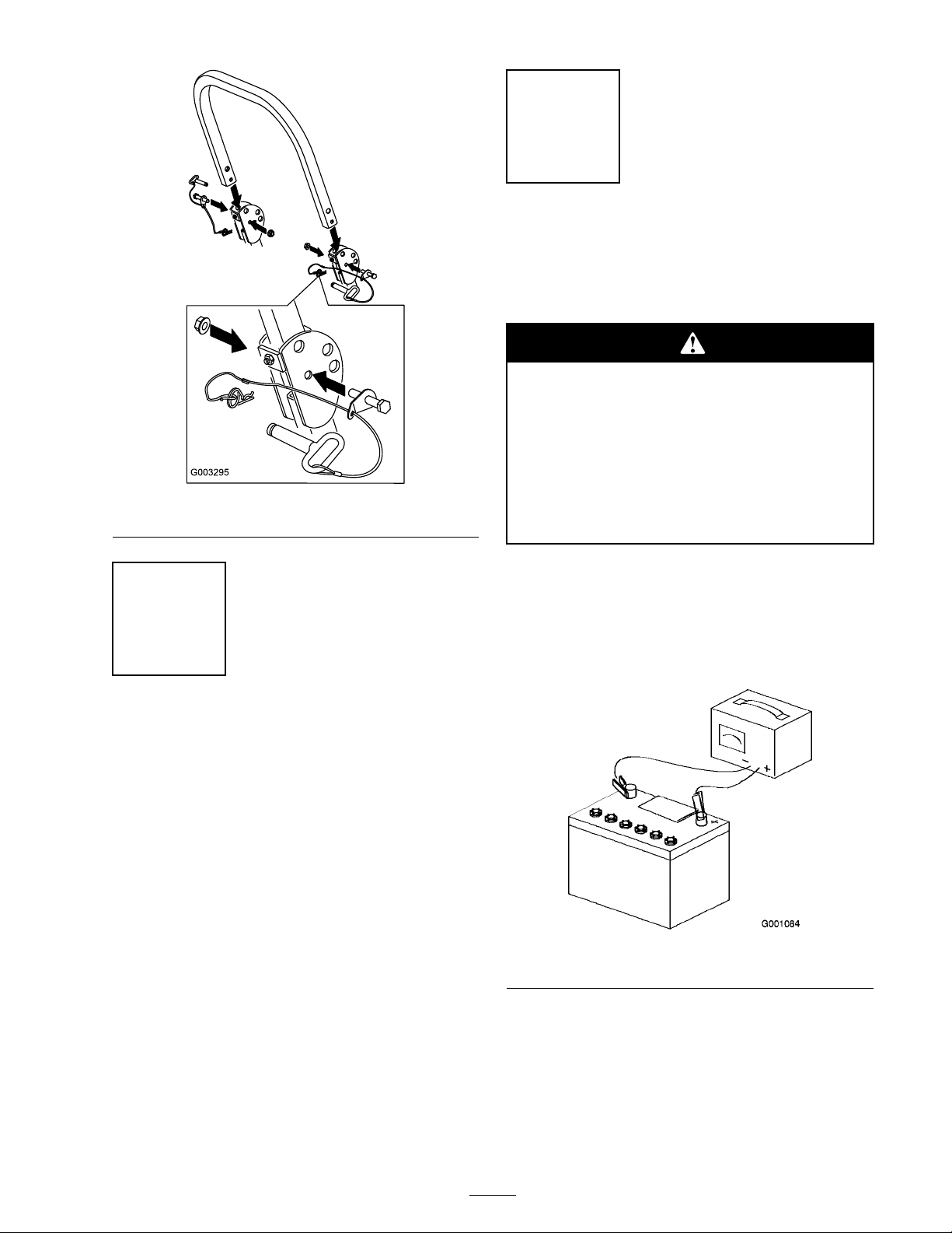
Battery
Ignition switch
Throttle lever
Glow plug light and switch
Power take off switch (PTO)
Motion control levers
Parking brake
Mower height-of-cut
Lift assist lever
Z Stand®
Adjustable seat
Hydraulic bypass valves
Rollover Protection System (ROPS)
Mower deck ow bafe
Refer to the Operator’s Manual to point out safety procedures, operation,and maintenance procedures.
Review the warranty statement as shown in the Operator’s Manual.
Describe the post sale service procedures for your store.
Assist the customer in lling out and mailing the registration card orregister online at www.Toro.com
Make sure that the customer receives the Operator’s Manual, Parts Catalog,Engine Owner’s Manual, Set Up Instructions, and safety video.
Assist the customer in loading the mower.
Note: W hen y ou, the dealer re presentati v e , ha v e finished deli v ering the mac hine to the customer , sign
and date in the space pro vide belo w and k ee p a copy of this pag e for dealer records .
Signature: Date:
Signature: Date:
10