Toro 31230 User manual

FormNo.3400-574RevA
Groundsmaster®3602-Wheel
DriveMulti-PurposeMachine
ModelNo.31230—SerialNo.316000001andUp
Registeratwww.Toro.com.
OriginalInstructions(EN)*3400-574*A

ThisproductcomplieswithallrelevantEuropeandirectives.
Fordetails,pleaseseetheseparateproductspecic
DeclarationofConformity(DOC)sheet.
WARNING
CALIFORNIA
Proposition65Warning
Thisproductcontainsachemicalorchemicals
knowntotheStateofCaliforniatocausecancer,
birthdefects,orreproductiveharm.
Dieselengineexhaustandsomeofits
constituentsareknowntotheStateof
Californiatocausecancer,birthdefects,
andotherreproductiveharm.
ItisaviolationofCaliforniaPublicResourceCode
Section4442or4443touseoroperatetheengineonany
forest-covered,brush-covered,orgrass-coveredlandunless
theengineisequippedwithasparkarrester,asdenedin
Section4442,maintainedineffectiveworkingorderorthe
engineisconstructed,equipped,andmaintainedforthe
preventionofre.
Introduction
Thismachineisaride-on,rotary-blademachineintended
tobeusedbyprofessional,hiredoperatorsincommercial
applications.Itisdesignedprimarilyforcuttinggrass
onwell-maintainedlawnsinparks,sportselds,andon
commercialgrounds.Itisnotdesignedforcuttingbrush,
mowinggrassandothergrowthalongsidehighways,orfor
agriculturaluses.
Readthisinformationcarefullytolearnhowtooperateand
maintainyourproductproperlyandtoavoidinjuryand
productdamage.Youareresponsibleforoperatingthe
productproperlyandsafely.
YoumaycontactTorodirectlyatwww.Toro.comforproduct
safetyandoperationtrainingmaterials,accessoryinformation,
helpndingadealer,ortoregisteryourproduct.
Wheneveryouneedservice,genuineToroparts,oradditional
information,contactanAuthorizedServiceDealerorToro
CustomerServiceandhavethemodelandserialnumbersof
yourproductready.Figure1identiesthelocationofthe
modelandserialnumbersontheproduct.Writethenumbers
inthespaceprovided.
Figure1
1.Modelandserialnumberlocation
ModelNo.
SerialNo.
Thismanualidentiespotentialhazardsandhassafety
messagesidentiedbythesafety-alertsymbol(Figure2),
whichsignalsahazardthatmaycauseseriousinjuryordeath
ifyoudonotfollowtherecommendedprecautions.
Figure2
1.Safety-alertsymbol
Thismanualuses2wordstohighlightinformation.
Importantcallsattentiontospecialmechanicalinformation
andNoteemphasizesgeneralinformationworthyofspecial
attention.
©2015—TheToro®Company
8111LyndaleAvenueSouth
Bloomington,MN554202
Contactusatwww.Toro.com.
PrintedintheUSA
AllRightsReserved

Contents
Safety...........................................................................4
GeneralSafety.........................................................4
VibrationLevel.......................................................4
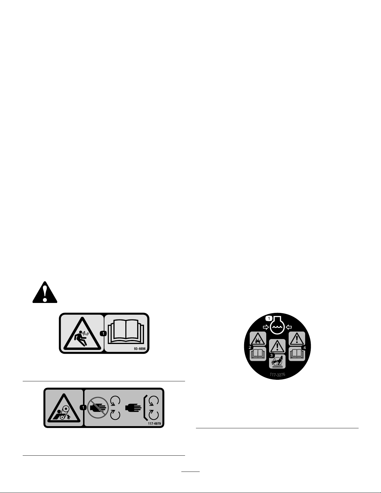
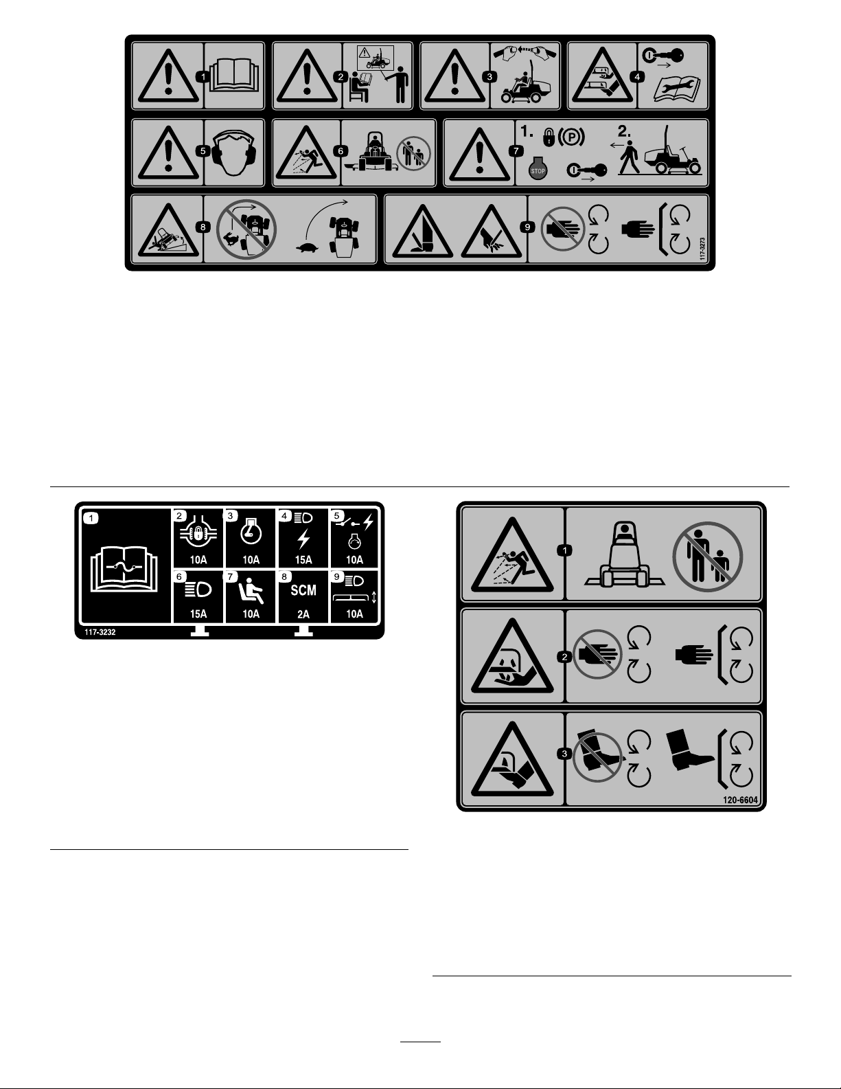
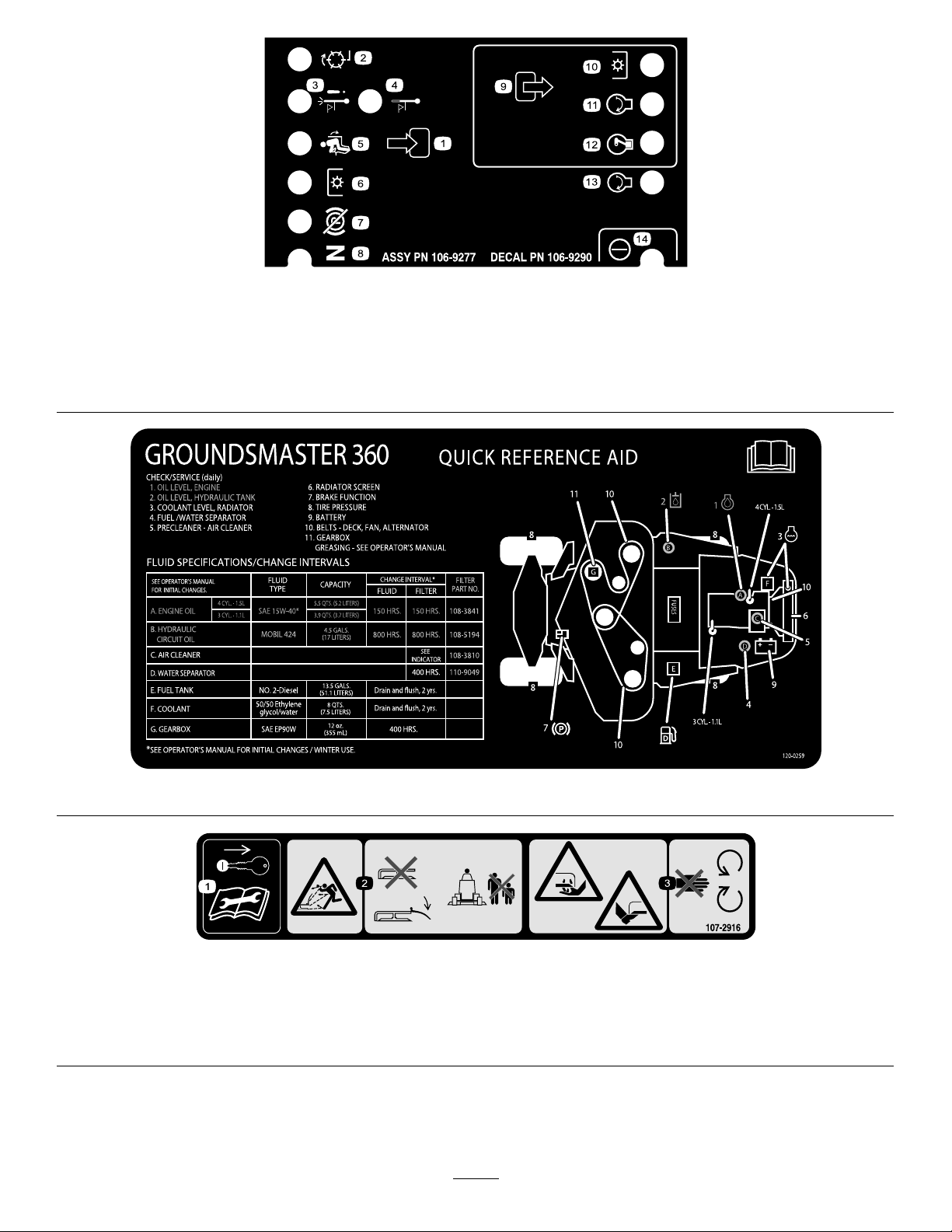
SafetyandInstructionalDecals.................................4
Setup............................................................................9
1AdjustingtheROPS..............................................9
2CheckingtheTirePressure.....................................9
3CheckingtheFluidLevels.....................................10
ProductOverview.........................................................10
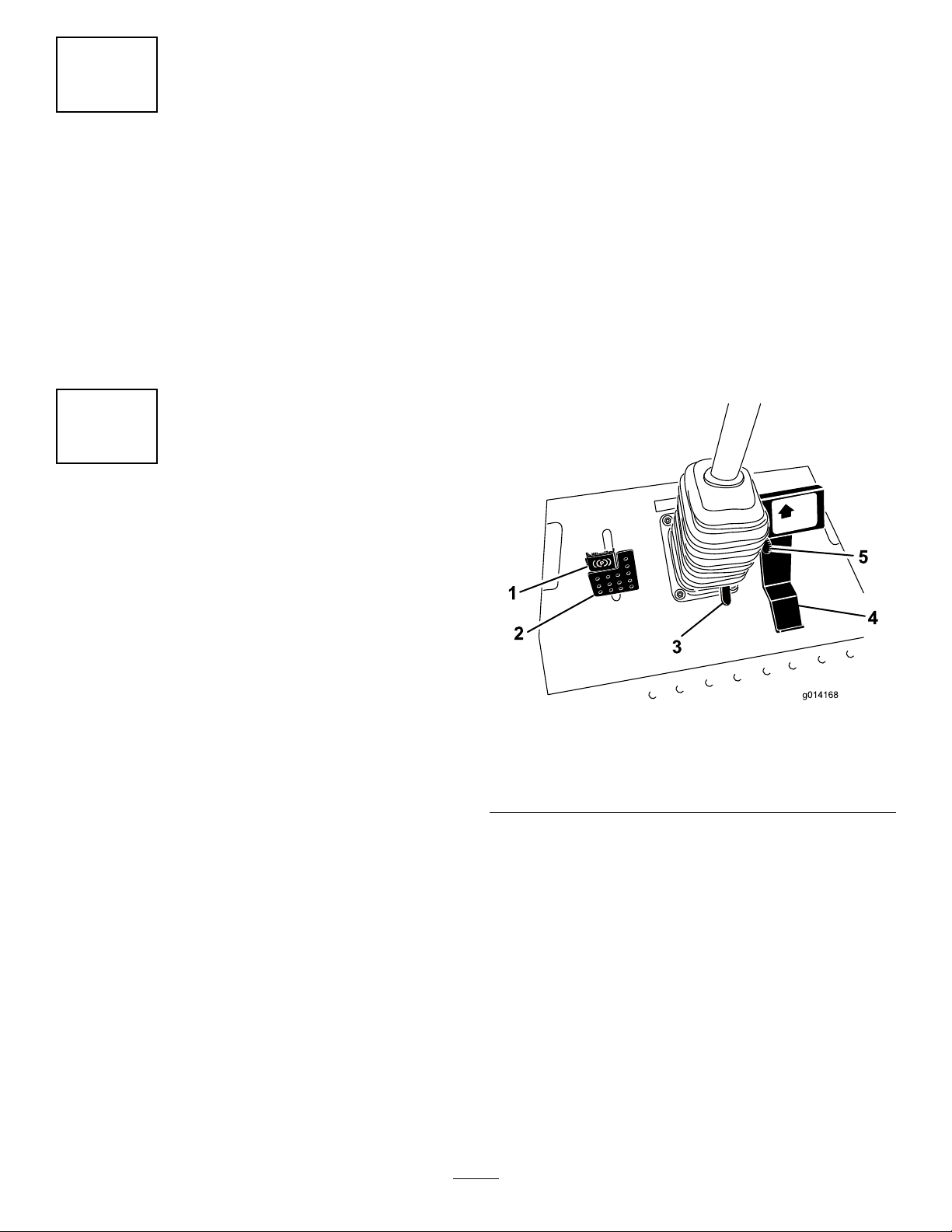
Controls...............................................................10
Specications........................................................12
Attachments/Accessories........................................12
BeforeOperation......................................................12
BeforeOperationSafety..........................................12
FillingtheFuelTank...............................................13
PositioningtheStandardSeat...................................14
PositioningtheDeluxeSeat......................................15
RaisingandLoweringtheSeat..................................16
DuringOperation.....................................................16
DuringOperationSafety.........................................16
ThinkSafetyFirst...................................................17
UsingtheRollover-ProtectionSystem(ROPS)............17
StartingandShuttingofftheEngine..........................18
DrivingtheMachine...............................................19
StoppingtheMachine.............................................19
TheSafety-InterlockSystem....................................19
UnderstandingtheDiagnosticLight..........................20
DiagnosticAceDisplay...........................................20
CheckingtheInterlockSwitches...............................21
OperatingtheMower..............................................22
OperatingTips......................................................23
AfterOperation........................................................23
AfterOperationSafety............................................23
PushingtheMachinebyHand..................................23
HaulingtheMachine...............................................24
Maintenance.................................................................25
RecommendedMaintenanceSchedule(s)......................25
DailyMaintenanceChecklist....................................26
PremaintenanceProcedures........................................27
Pre-MaintenanceSafety...........................................27
PreparingtheMachineforMaintenance.....................27
UsingtheHood-PropRod.......................................28
Lubrication...............................................................28
GreasingtheBearingsandBushings..........................28
EngineMaintenance..................................................30
EngineSafety.........................................................30
ServicingtheAirCleaner.........................................30
CheckingtheEngine-OilLevel.................................30
ChangingtheEngineOilandFilter...........................31
AdjustingtheThrottle.............................................32
FuelSystemMaintenance...........................................32
ServicingtheWaterSeparator..................................32
BleedingtheFuelSystem.........................................33
BleedingAirfromtheFuelInjectors..........................33
CleaningtheFuelTank............................................33
CheckingtheFuelLinesandConnections..................34
ElectricalSystemMaintenance....................................34
ElectricalSystemSafety...........................................34
CheckingtheFuses.................................................34
ServicingtheBattery...............................................35
StoringtheBattery..................................................35
DriveSystemMaintenance.........................................36
CheckingtheTirePressure......................................36
CoolingSystemMaintenance......................................36
CoolingSystemSafety.............................................36
CheckingtheCoolingSystem..................................36
BrakeMaintenance....................................................37
AdjustingtheServiceBrakes....................................37
AdjustingtheParkingBrake....................................37
BeltMaintenance......................................................38
CheckingtheAlternatorBelt...................................38
ControlsSystemMaintenance.....................................39
AdjustingtheTractionDriveforNeutral....................39
AdjustingtheMaximumGroundSpeed.....................39
HydraulicSystemMaintenance....................................40
HydraulicSystemSafety..........................................40
CheckingtheHydraulicSystem................................40
ChangingtheHydraulicFluidandFilter.....................41
Storage........................................................................42
ServicingtheEngine...............................................42
ServicingtheMachine.............................................42
3

Safety
ThismachinehasbeendesignedinaccordancewithENISO
5395:2013andANSIB71.4-2012.
GeneralSafety
Thisproductiscapableofamputatinghandsandfeetand
ofthrowingobjects.Alwaysfollowallsafetyinstructionsto
avoidseriouspersonalinjury.
Usingthisproductforpurposesotherthanitsintendeduse
couldprovedangeroustoyouandbystanders.
•ReadandunderstandthecontentsofthisOperator’sManual
beforeyoustarttheengine.Ensurethateveryoneusing
thisproductknowshowtouseitandunderstandsthe
warnings.
•Donotputyourhandsorfeetnearmovingcomponents
ofthemachine.
•Donotoperatethemachinewithoutallguardsandother
safetyprotectivedevicesinplaceandworkingonthe
machine.
•Keepclearofanydischargeopening.Keepbystandersa
safedistancefromthemachine.
•Keepchildrenoutoftheoperatingarea.Neverallow
childrentooperatethemachine.
•Stopthemachineandshutofftheenginebeforeservicing,
fueling,oruncloggingthemachine.
Improperlyusingormaintainingthismachinecanresult
ininjury.Toreducethepotentialforinjury,complywith
thesesafetyinstructionsandalwayspayattentiontothe
safety-alertsymbol,whichmeansCaution,Warning,or
Danger—personalsafetyinstruction.Failuretocomplywith
theseinstructionsmayresultinpersonalinjuryordeath.
Youcanndadditionalitemsofsafetyinformationintheir
respectivesectionsthroughoutthismanual.
VibrationLevel
CEModelOnly
Hand-Arm
Measuredvibrationlevelforrighthand=0.39m/s2
Measuredvibrationlevelforlefthand=0.34m/s2
UncertaintyValue(K)=0.5m/s2
Measuredvaluesweredeterminedaccordingtotheprocedures
outlinedinENISO5395:2013.
WholeBody
Measuredvibrationlevel=0.54m/s2
UncertaintyValue(K)=0.5m/s2
Measuredvaluesweredeterminedaccordingtotheprocedures
outlinedinENISO5395:2013.
SafetyandInstructionalDecals
Safetydecalsandinstructionsareeasilyvisibletotheoperatorandarelocatednearanyareaofpotential
danger.Replaceanydecalthatisdamagedorlost.
93-6696
1.Storedenergyhazard—readtheOperator'sManual.
117-4979
1.Rotatingbelt—Keepguardinplace
117-3276
1.Enginecoolantunder
pressure
3.Warning—donottouchthe
hotsurface.
2.Explosionhazard—read
theOperator'sManual.
4.Warning—readthe
Operator'sManual.
4

117-3272
1.Warning—readtheOperator'sManual;failuretousthe
rollover-protectionsystem(ROPS)canresultininjuryin
theeventofarollover;wearaseatbeltwhenaROPSisin
place;donotwearaseatbeltwhenROPSislowered.
106-2353
1.Electrical-powerpoint
117-4766
1.Cutting/dismembermenthazard;fan—stayawayfrom
movingparts,keepallguardsandshieldsinplace.
117-3270
1.Warning—donottouchthehotsurface.
2.Cutting/dismembermenthazard,hand;entanglement
hazard,belt—stayawayfrommovingparts,keepallguards
andshieldsinplace.
117-2718
106-9206
1.Wheeltorquespecications
2.ReadtheOperator'sManual.
5

117-3273
1.Warning—readtheOperator'sManual.6.Thrownobjecthazard—keepbystandersasafedistancefrom
themachine.
2.Warning—donotoperatethismachineunlessyouaretrained.7.Warning—locktheparkingbrake,stoptheengine,and
removetheignitionkeybeforeleavingthemachine.
3.Warning—weartheseatbeltwhenseatedintheoperator's
position.
8.Tippinghazard—lowerthecuttingunitwhendrivingdown
slopes;slowthemachinebeforeturning,donotturnathigh
speeds.
4.Cutting/dismembermenthazardofhandorfoot—removethe
ignitionkeyandreadtheinstructionsbeforeservicingor
performingmaintenance.
9.Cuttinghazardofhandorfoot—stayawayfrommovingparts;
keepallguardsinplace.
5.Warning—wearhearingprotection.
117-3232
1.ReadtheOperator'sManualforinformationonfuses.
2.Differentiallockout—10A
3.Engine—10A
4.Lights,powerpoint—15A
5.Powerswitch,engineignition—10A
6.Lights—15A
7.Operatorpresenceswitch—10A
8.Computer—2A
9.Headlights,deckactuator—10A120-6604
1.Thrownobjecthazard—keepbystandersawayfromthe
machine.
2.Cutting/dismembermenthazardofhand,mower
blade—stayawayfrommovingparts,keepallguardsand
shieldsinplace.
3.Cutting/dismembermenthazardoffoot,mowerblade—stay
awayfrommovingparts,keepallguardsandshieldsin
place.
6

106-9290
1.Inputs5.Inseat9.Outputs13.Start
2.Notactive6.PowerT akeoff(PTO)10.PowerT akeoff(PTO)14.Power
3.High-temperature
shutdown
7.Parkingbrakeoff11.Start
4.High-temperaturewarning8.Neutral12.Energizetorun(ETR)
120-0259
107-2916
1.Removetheignitionkeyandreadthe
Operator'sManualbeforeservicingor
performingmaintenance.
2.Thrownobjecthazard—donotoperate
themowerwiththedeectorupor
removed,keepthedeectorinplace;
keepbystandersasafedistancefrom
themachine.
3.Cutting/dismembermenthazardof
handorfoot,mowerblade—stayaway
frommovingparts.
7

115-0492
1.Heightofcut(mm)
BatterySymbols
Someorallofthesesymbolsareonyourbattery.
1.Explosionhazard6.Keepbystandersasafe
distancefromthebattery.
2.Nore,opename,or
smoking
7.Weareyeprotection;
explosivegasescan
causeblindnessandother
injuries.
3.Causticliquid/chemical
burnhazard
8.Batteryacidcancause
blindnessorsevereburns.
4.Weareyeprotection.9.Flusheyesimmediately
withwaterandgetmedical
helpfast.
5.ReadtheOperator's
Manual.
10.Containslead;donot
discard
120-0257
1.Lowerdecks6.Differentiallock
2.Raisedecks7.Fast
3.Engine—stop8.Continuousvariable
setting
4.Engine—run9.Slow
5.Engine—start
8

Setup
LooseParts
Usethechartbelowtoverifythatallpartshavebeenshipped.
ProcedureDescriptionQty.Use
1Nopartsrequired–AdjusttheROPS.
2Nopartsrequired–Checkthetirepressure.
3Nopartsrequired–Checkthehydraulicuid,engineoil,
andcoolantlevels.
MediaandAdditionalParts
DescriptionQty.Use
Operator'sManual1Readbeforeoperatingthemachine
Engineoperator'smanual1Readbeforeoperatingthemachine
PartsCatalog1Usetoreferencepartnumbers
Operatortrainingmaterials1Viewthevideobeforeoperatingthemachine.
1
AdjustingtheROPS
NoPartsRequired
Procedure
1.Removethehairpincottersandthepinsfromtheroll
bar(Figure3).
2.Raisetherollbartotheuprightpositionandinstallthe
2pinsandsecurethemwiththehairpincotters(Figure
3).
Note:Ifyoumustlowertherollbar,pushthebar
forwardtorelievepressureonthepins,removethe
pins,lowerthebarslowly,andsecureitwiththepinsso
thatitdoesnotdamagethehood.
Figure3
1.Rollbar3.Hairpincotter
2.Pin
9

2
CheckingtheTirePressure
NoPartsRequired
Procedure
Thetiresareover-inatedforshipping.Therefore,release
someoftheairtoreducethepressure.Thecorrectair
pressurefornon-cabmodelsis103kPa(15psi)inthefront
tiresand172kPa(25psi)inthereartires.Ifacabisonthe
machine,thefrontandreartiresshouldbeinatedto172
kPa(25psi).
3
CheckingtheFluidLevels
NoPartsRequired
Procedure
1.Checkthehydraulic-uidlevelbeforestartingthe
engine;refertoCheckingtheHydraulicSystem(page
40).
2.Checktheengine-oillevelbeforestartingtheengine;
refertoCheckingtheEngine-OilLevel(page30).
3.Checkthecoolingsystembeforestartingtheengine;
refertoCheckingtheCoolingSystem(page36).
ProductOverview
Controls
Becomefamiliarwithallthecontrolsbeforeyoustartthe
engineandoperatethemachine.
TractionPedal
Thetractionpedal(Figure4)controlstheforwardandreverse
operation.Pressthetopofthepedaltomoveforwardand
thebottomtomoverearward.Thegroundspeeddependson
howfaryoupressthepedal.Fornoload,maximumground
speed,fullypressthepedalwhilethethrottleisintheFAST
position.
Tostopthemachine,reducethefootpressureonthetraction
pedalandallowittoreturntothecenterposition.
Figure4
1.Parkingbrake4.Tractionpedal
2.Brakepedal5.Mow-speedlimiter
3.Tilt-steeringpedal
BrakePedal
Usethebrakepedalwiththebrake-pedallatchtoengageand
disengagetheparkingbrake(Figure4).Tostopthemachine,
releasethetractionpedalandallowittoreturntothecenter
position.Youcanusethebraketoassistinstoppingthe
machineinanemergencysituation.
ParkingBrake
Toengagetheparkingbrake,pushdownonthebrakepedal
andpressthetopforwardtolatchit(Figure4).Toreleasethe
parkingbrake,pressthebrakepedaluntiltheparking-brake
latchretracts.
10

TiltSteeringPedal
Totiltthesteeringwheeltowardyou,pressthefootpedal
down,pullthesteeringtowertowardyoutothemost
comfortableposition,andreleasethepedal(Figure4).
IgnitionSwitch
Theignitionswitchhas3positions:OFF,ON/PREHEAT,and
START(Figure5).
Figure5
1.Power-takeoff(PTO)
switch
8.Diagnosticlight
(4-wheel-driveonly)
2.Oil-pressure-warninglight9.Ignitionswitch
3.Charge-indicatorlight10.Powerpoint
4.Hourmeter11.Optionalswitchlocation
5.Differential-lockswitch
(2-wheel-driveonly)
12.Deck-liftswitch
6.Steering-selectorswitch
(4-wheel-driveonly)
13.Glow-pluglight
7.Throttlelever14.Coolant-temperature-warning
light
ThrottleLever
Thethrottlelever(Figure5)controlstheenginespeed.
MovingthethrottleleverforwardtowardtheFASTposition
increasestheenginespeed.Movingitrearwardtowardthe
SLOWpositiondecreasestheenginespeed.Thethrottle
controlsthespeedofthebladesand,withthetractionpedal,
controlsthegroundspeedofthemachine.Alwaysrunthe
machinewiththethrottleintheFASTpositionwhencutting
grass.
Power-Takeoff(PTO)Switch
Thepower-takeoff(PTO)switchstartsandstopsthemower
blades(Figure5).
HourMeter
Thehourmeter(Figure5)recordsthenumberofhoursthat
theenginehasoperated.Itoperateswhenthekeyswitchis
intheRUNposition.Usethesetimesforschedulingregular
maintenance.
Differential-LockSwitch
Pressthefrontoftheswitchandholditdowntoengagethe
differentiallock(Figure5).
Glow-Plug-IndicatorLight(Orange
Light)
Theglow-plug-indicatorlight(Figure5)turnsonwhenyou
turntheignitionswitchtotheONposition.Itremainsonfor
6seconds.Whenthelightturnsoff,youcanstarttheengine.
Engine-Coolant-Temperature-Warning
Light
Thislightglowsandtheattachmentstopsifthetemperature
oftheenginecoolantishigh(Figure5).Ifyoudonotstop
themachineandthecoolanttemperaturerisesanother7°C
(20°F),theengineshutsoff.
Important:Iftheattachmentshutsdownandthe
temperature-warninglightison,pushthePTOknob
down,drivethemachinetoasafe,atarea,movethe
throttlelevertotheSLOWposition,allowthetraction
pedaltomovetotheNEUTRALposition,andengage
theparkingbrake.Allowtheenginetoidleforseveral
minuteswhileitcoolstoasafelevel.Shutofftheengine
andcheckthecoolingsystem;refertoCheckingthe
CoolingSystem(page36).
ChargeIndicator
Thechargeindicatorilluminateswhenthecharging-system
circuitmalfunctions(Figure5).
Oil-Pressure-WarningLight
Theoil-pressure-warninglight(Figure5)glowswhentheoil
pressureinenginedropsbelowasafelevel.Iflowoilpressure
everoccurs,shutofftheengineanddeterminethecause.
Repairthedamagebeforestartingtheengineagain.
FuelGauge
Thefuelgauge(Figure6)indicatestheamountoffuel
remaininginthefueltank.
11

Figure6
1.Fuelgauge2.Fuel-tankcap
Specications
Note:Specicationsanddesignaresubjecttochange
withoutnotice.
Length241.3cm(95inches)
Width(RearWheels)144.8cm(78inches)
Height
WithRollBarup144.8cm(78inches)
WithRollBardown54inches(137.2cm)
Weight
Model31230with60-inch
basedeck(Model30457)
2,776lb
Model31230with60-inch
side-dischargedeck(Model
30456)
2,806lb
Model31230with72-inch
basedeck(Model30353)
2,814lb
Model31230with72-inch
side-dischargedeck(Model
30354or30481)
2,862lb
Attachments/Accessories
AselectionofToroapprovedattachmentsandaccessoriesis
availableforusewiththemachinetoenhanceandexpand
itscapabilities.ContactyourAuthorizedServiceDealeror
Distributororgotowww .Toro.comforalistofallapproved
attachmentsandaccessories.
Operation
Note:Determinetheleftandrightsidesofthemachine
fromthenormaloperatingposition.
BeforeOperation
BeforeOperationSafety
GeneralSafety
•Neverallowchildrenoruntrainedpeopletooperateor
servicethemachine.Localregulationsmayrestrictthe
ageoftheoperator.Theownerisresponsiblefortraining
alloperatorsandmechanics.
•Becomefamiliarwiththesafeoperationoftheequipment,
operatorcontrols,andsafetysigns.Knowhowtostop
themachineandenginequickly.
•Checkthatallsafetydevicesareattachedand
functioningproperly.Thisincludes,butisnotlimitedto,
operator-presencecontrols;safetyswitchesandshields;
therolloverprotectionsystem(ROPS);attachments;and
brakes.Donotoperatethemachineunlessallsafety
devicesareinpositionandfunctioningasintendedby
themanufacturer.
•Alwaysinspectthemachinetoensurethattheblades,
bladebolts,andcuttingassemblyarenotwornor
damaged.Replacewornordamagedbladesandboltsin
setstopreservebalance.
•Inspecttheareawhereyouwillusethemachineand
removeallobjectsthatthemachinecouldpotentially
throw .
•Evaluatetheterraintodeterminetheappropriate
equipmentandanyattachmentsoraccessoriesrequiredto
operatethemachineproperlyandsafely.
12

FuelSafety
DANGER
Incertainconditions,fuelisextremelyammable
andhighlyexplosive.Areorexplosionfromfuel
canburnyouandothersandcandamageproperty.
•Fillthefueltankoutdoors,inanopenarea,when
theengineiscold.Wipeupanyfuelthatspills.
•Neverllthefueltankinsideanenclosedtrailer.
•Neversmokewhenhandlingfuel,andstayaway
fromanopenameorwherefuelfumesmaybe
ignitedbyaspark.
•Storefuelinanapprovedcontainerandkeepit
outofthereachofchildren.Neverbuymore
thana180-daysupplyoffuel.
•Donotoperatethemachinewithouttheentire
exhaustsysteminplaceandinproperworking
condition.
WARNING
Fuelisharmfulorfatalifswallowed.Long-term
exposuretovaporscancauseseriousinjuryand
illness.
•Avoidprolongedbreathingofvapors.
•Keepyourhandsandfaceawayfromthenozzle
andthefuel-tankopening.
•Keepfuelawayfromyoureyesandskin.
•Useonlyanapprovedfuelcontainer.
•Neverremovethefuelcaporaddfueltothefueltank
whiletheengineisrunning.
•Neverllcontainersinsideavehicleoronatruckor
trailerbedwithaplasticliner.Alwaysplacecontainerson
thegroundandawayfromyourvehiclebeforelling.
•Removetheequipmentfromthetruckortrailerandadd
fueltoitwhileitisontheground.Ifthisisnotpossible,
thenaddfuelusingaportablecontainerratherthanfrom
afuel-dispensernozzle.
•Keepthefuel-dispensernozzleincontactwiththerimof
thefueltankorcontaineropeningatalltimesuntilfueling
iscomplete.Donotuseanozzlelock-opendevice.
•Ifyouspillfuelonyourclothing,changeyourclothing
immediately.
•Fillthefueltankuntilthefuellevelis25mm(1inch)
belowthebottomofthellerneck.Donotoverllthe
fueltank.Replacethefuel-tankcapandtightenitsecurely.
FillingtheFuelTank
RecommendedFuel
Useonlyclean,freshdieselfuelorbiodieselfuelswithlow
(<500ppm)orultralow(<15ppm)sulfurcontent.The
minimumcetaneratingshouldbe40.Purchasefuelin
quantitiesthatyoucanusewithin180daystoensurethat
thefuelisfresh.
FuelTankCapacity:51L(13.5USgallons)
Usesummer-gradedieselfuel(No.2-D)attemperatures
above-7°C(20°F)andwintergrade(No.1-DorNo.
1-D/2-Dblend)belowthattemperature.Usingwinter-grade
fuelatlowertemperaturesprovidealowerashpointand
cold-owcharacteristics,whicheasesstartingandreduces
pluggingofthefuellter.
Usingsummer-gradefuelabove-7°C(20°F)contributes
towardlongerlifeofthefuelpumpandincreasedpower
comparedtowinter-gradefuel.
Important:Donotusekeroseneorgasolineinsteadof
dieselfuel.Failingtoobservethiscautionwilldamage
theengine.
BiodieselReady
Thismachinecanalsouseabiodieselblendedfuelofup
toB20(20%biodiesel,80%petrodiesel).Thepetrodiesel
portionshouldbeultra-lowsulfur.Observethefollowing
precautions:
•Thebiodieselportionofthefuelmustmeetspecication
ASTMD6751orEN14214.
•TheblendedfuelcompositionshouldmeetASTMD975
orEN590.
•Biodieselblendsmaydamagepaintedsurfaces.
•UseB5(biodieselcontentof5%)orlesserblendsincold
weather.
•Checkallseals,hoses,andgasketsincontactwithfuelas
theymaydegradeovertime.
•Espectthefuelltertoplugupforatimeafterconverting
tobiodiesel-blendedfuel.
•Contactyourdistributorformoreinformationon
biodieselfuel.
Note:Ifpossible,llthefueltankaftereachuse.This
minimizespossiblebuildupofcondensationinsidethefuel
tank.
1.Parkthemachineonalevelsurface.
2.Shutofftheengineandsettheparkingbrake.
3.Cleanaroundthefuel-tankcapandremovethecap
(Figure7).
13

Figure7
1.Fuelgauge
2.Fuel-tankcap
Important:Donotopenthefueltankwhen
parkedonahill.Thefuelcouldspillout.
4.Addfueltothefueltankuntilthelevelisevenwith
thebottomofthellerneck.Donotoverllthefuel
tank.
5.Installthefuel-tankcapandsecure.Wipeupany
spilledfuel.
PositioningtheStandardSeat
ChangingtheSeatPosition
Theseatcanmoveforwardandbackward.Positiontheseat
whereyouhavethebestcontrolofthemachineandaremost
comfortable.
1.Toadjusttheseat,movetheleversidewaystounlock
theseat(Figure8).
Figure8
1.Backrestknob3.Lumbar-support-adjustment
knob
2.Seat-suspensionknob4.Seat-position-adjustment
lever
2.Slidetheseattothedesiredpositionandreleasethe
levertolocktheseatinposition.
3.Verifythattheseathaslockedintoplacebyattempting
tomoveitbackandforth.
ChangingtheSeatSuspension
Youcanadjusttheseattoprovideasmoothandcomfortable
ride.Positiontheseatwhereyouaremostcomfortable.
Withoutsittingontheseat,turntheknobinfrontineither
directiontoprovidethebestcomfort(Figure8).
Figure9
1.Seat-suspensionknob2.Operator-weightsetting
ChangingtheBackPosition
Youcanadjustthebackoftheseattoprovideacomfortable
ride.Positionthebackoftheseatwhereitismost
comfortable.
14

Toadjustthebackoftheseat,turntheknob,locatedunder
theright-sidearmrest,ineitherdirectiontoprovidethebest
comfort(Figure8).
ChangingtheLumbarSupport
Youcanadjustthebackoftheseattoprovideacustomized
lumbarsupportforyourlowerback.
Toadjustthebackoftheseat,turntheknob,underthe
left-sidearmrest,ineitherdirectiontoprovidethebest
comfort(Figure8).
PositioningtheDeluxeSeat
Figure10
1.Forward-/Rearward-adjustment
lever
4.Armrest-adjustmentknob
2.Weight-adjustmentlever5.Lumbar-support-adjusting
knob
3.Backrest-lockinglever
ChangingtheWeightAdjustment
Youcanadjusttheseattoprovideasmoothandcomfortable
ride.
Important:Toadjusttheseatforyourweight,you
mustsitintheseatandmovetheignitionkeytotheON
position.
Adjusttheseatforyourweightbypullingorpressingthe
weight-adjustmentlever(Figure10).
Yourweightisadjustedcorrectlywhenthearrowisinthe
middleclearareaoftheviewingwindow.
Withinthisviewingarea,youcanadjusttheseattominimize
thespringmovement.
Whenyouhavesettheminimum/maximumweight
adjustment,youcanhearitreachingtheupperorlowerend
stop.
Important:Topreventinjurytoyouordamagetothe
machine,checkthesettingforyourweightandtheseat
andadjusteditbeforeyouoperatethemachine.
Note:Toavoiddamagingthecompressorduringtheweight
adjustment,donotoperatethecompressorlongerthan1
minute.
ChangingtheSeatPosition
Theseatcanmoveforwardandbackward.Positiontheseat
whereyouhavethebestcontrolofthemachineandaremost
comfortable.
1.Liftthelevertounlocktheseat(Figure10).
2.Slidetheseattothedesiredpositionandreleaselever
tolockitintoposition.
3.Verifythattheseathaslockedintoplacebyattempting
tomoveitbackandforth.
Note:Donotoperatethelockingleverwhile
operatingthemachine.
ChangingtheLumbarSupport
Thelumbarsupportincreasesbothyourseatingcomfortand
performance.
Youcanadjustthebackoftheseattoprovideacustomized
lumbarsupportforyourlowerback.
Byturningtheadjustmentknobupward,youcanadjustthe
curvatureintheupperpartofthebackrestcushion.By
turningtheknobdownwardsyoucanadjustthecurvaturein
thelowerpartofthebackrestcushion(Figure10).
0=Nocurvature
1=Maximumcurvatureatthetop
2=Maximumcurvatureatthebottom
AdjustingtheArmrests
Youcanfoldbackthearmrestsandadjusttheheight
individually.
Toadjustthearmrestsforheight,separatetheroundcap
(Figure10)fromthecover,loosenthehexagonnut(13mm)
behindit,adjustthearmreststothedesiredposition,and
tightenthenut.Replacethecapontothenut.
Donotinstallthearmrestinthelowestposition,astheseat
beltrollermightnotfunctionproperly.
ChangingtheArmrestAngle
Youcanadjusttheangleofthearmrestsforyourcomfort.
Toadjusttheangleofthearmrests,turntheadjustmentknob
(Figure10).
Turningtheknobtotheoutside(+)raisesthefrontpartof
thearmrest;turningtheknobtotheinside(-)lowersit.
15

ChangingtheBackrestPosition
Youcanadjustthebackoftheseattoprovideamore
comfortableride.Positionthebackoftheseatwhereitis
mostcomfortable.
Pullupthelockinglevertoreleasethebackrestcatch(Figure
10).Whenreleasingthebackrestcatch,donotapplyloadto
thebackrestbypressingagainstit.
Byexertingpressureonoroffthefrontorrearoftheseat,
youcanmovetheseattothedesiredposition.Releasethe
lockinglevertolockthebackrest.
Note:Thebackrestshouldnotbeabletomovetheinto
anotherpositionafteryouhavelockedit.
RaisingandLoweringtheSeat
Toaccessthehydraulicandothersystemsundertheseat,you
mustunlatchtheseatandswingitforward.
1.Movetheseatlatch,locatedontheleftsideoftheseat,
rearwardtounlatchtheseatandpullforwardonthe
topoftheseat(Figure11).
Figure11
1.Seatlatch
2.Tolowertheseat,pulluptheseat-latch-releasebarand
lowertheseatintothelockedposition.
Figure12
1.Seat-latch-releasebar
DuringOperation
DuringOperationSafety
GeneralSafety
•Theowner/usercanpreventandisresponsiblefor
accidentsthatmaycauseinjuriestohimself/herselfand
othersandfordamagetoproperty.
•Wearappropriateclothing,includingeyeprotection;
slip-resistant,substantialfootwear;andhearing
protection.Wearingsafetyshoesandlongpantsis
advisableandrequiredbysomelocalordinancesand
insuranceregulations.Tiebacklonghair,secureloose
clothing,anddonotwearjewelry.
•EnsurethatalldrivesareintheNEUTRALposition,the
parkingbrakeisengaged,andyouareintheoperating
positionbeforeyoustarttheengine.
•Keepallbodyparts,includinghandsandfeet,awayfrom
allmovingparts.
•Donotoperatethemachinewhileill,tired,orunderthe
inuenceofalcoholordrugs.
•Keepthedirectionofthemowerdischargeawayfrom
peopleandpets.
•Donotmowinreverseunlessitisabsolutelynecessary.If
youmustmowinreverse,lookbehindanddownforsmall
childrenbeforeandwhilemovingthemachineinreverse.
Stayalertandstopthemachineifachildentersthearea.
•Useextremecarewhenapproachingblindcorners,
shrubs,trees,orotherobjectsthatmayblockyourview .
•Donotmowneardrop-offs,ditches,orembankments.
Themachinecouldsuddenlyrolloverifawheelgoes
overtheedgeoriftheedgecavesin.
•Nevercarrypassengersonthemachine.
16

•Operatethemachineonlyingoodvisibilityand
appropriateweatherconditions.Donotoperatethe
machinewhenthereistheriskoflighting.
•Donotmowonwetgrass.Reducedtractioncouldcause
themachinetoslide.
•Neverraisethemowerdeckwiththebladesrunning.
•Stopthemachineandinspectthebladesafterstrikingan
objectorifthereisanabnormalvibrationinthemachine.
Makeallnecessaryrepairsbeforeresumingoperation.
•Stopthebladeswheneveryouarenotmowing,especially
whilecrossinglooseterrainsuchasgravel.
•Slowdownandusecautionwhenmakingturnsand
crossingroadsandsidewalkswiththemachine.Always
yieldtheright-of-way.
•Turnontheashingwarninglightsonthemachine
wheneveryoutravelonapublicroad,exceptwheresuch
useisprohibitedbylaw .
•Disengagethedrivetotheattachmentandshutoffthe
enginebeforeaddingfuelandadjustingtheheightofcut.
•Reducethethrottlesettingbeforestoppingtheengine
and,iftheenginehasafuel-shutoffvalve,shutoffthe
fuelwhenyouhavenishedoperatingthemachine.
•Neverrunanengineinanareawhereexhaustgasesare
enclosed.
•Neverleavearunningengineunattended.
•Beforeleavingtheoperatingposition,dothefollowing:
–Stopthemachineonlevelground.
–Disengagethepowertake-offandlowerthe
attachments.
–Settheparkingbrake.
–Shutofftheengineandremovethekey.
–Waitforallmovingpartstostop.
•Donotchangethegovernorsettingsonoroverspeed
theengine.Operatingtheengineatexcessivespeedmay
increasethepotentialforpersonalinjury.
•Donotusethemachineasatowingvehicle.
•UseaccessoriesandattachmentsapprovedbyTheToro®
Companyonly.
RolloverProtectionSystem(ROPS)
Safety
•DonotremovetheROPSfromthemachine.
•Ensurethattheseatbeltisattachedandthatyoucan
releaseitquicklyintheeventofanemergency.
•AlwayswearyourseatbeltwhentheROPSisup.
•Checkcarefullyforoverheadclearances,suchasbranches,
doorways,andelectricalwires,beforedrivingthemachine
underthem.Donotcontactthem.
•KeeptheROPSinsafeoperatingconditionbythoroughly
inspectingitperiodicallyfordamageandkeepingallthe
mountingfastenerstight.
•ReplaceadamagedROPS.Donotrepairorreviseit.
•AnyalterationstoaROPSmustbeapprovedbyThe
Toro®Company.
SlopeSafety
•Slowdownthemachineanduseextracareonhillsides.
Travelintherecommendeddirectiononhillsides.Turf
conditionscanaffectthestabilityofthemachine.
•Avoidstarting,stopping,orturningthemachineona
slope.Ifthetireslosetraction,disengagetheblade(s)and
proceedslowlystraightdowntheslope.
•Donotturnthemachinesharply.Usecarewhenreversing
themachine.
•Whenoperatingthemachineonaslope,alwayskeepall
cuttingunitslowered.
•Avoidturningthemachineonslopes.Ifyoumustturn,
turnslowlyandgraduallydownhill,ifpossible.
•Useextracarewhileoperatingthemachinewith
attachments;theycanaffectthestabilityofthemachine.
ThinkSafetyFirst
Pleasereadallsafetyinstructionsandsymbolsinthesafety
section.Knowingthisinformationcouldhelpyouor
bystandersavoidinjury.
CAUTION
Thismachineproducessoundlevelsinexcessof
85dBAattheoperator’searandcancausehearing
lossthroughextendedperiodsofexposure.
Wearhearingprotectionwhenoperatingthis
machine.
Figure13
1.Warning—weareye
protection.
2.Warning—wearhearing
protection
UsingtheRollover-Protection
System(ROPS)
•Keeptherollbarintheraisedandlockedpositionand
usetheseatbeltwhenoperatingthemachine.
•Ensurethatyoucanreleasetheseatbeltquicklyinan
emergencysituation.
•Checktheareathatyouwillmowandneverfoldthe
ROPSinareaswherethereareslopes,drop-offs,orwater.
17

WARNING
Toavoidinjuryordeathfromrollover,keeptheroll
barintheraisedlockedpositionandusetheseat
belt.
Ensurethattheseatplateissecuredwiththeseat
latch.
WARNING
Youhavenorolloverprotectionwhentherollbar
isinthedownposition.
•Lowertherollbaronlywhennecessary.
•Donotweartheseatbeltwhentherollbaris
inthedownposition.
•Driveslowlyandcarefully.
•Raisetherollbarassoonasclearancepermits.
•Checkcarefullyforoverheadclearances(i.e.,
branches,doorways,electricalwires)before
drivingunderanyobjectsanddonotcontact
them.
1.Tolowertherollbar,removethehairpincotters,push
therollbarforwardagainstthesprings,andremove
the2pins(Figure14).
Figure14
1.Pin3.Rollbar(raisedposition)
2.Hairpincotter4.Rollbar(loweredposition)
2.Lowertherollbartothedownposition(Figure14).
3.Installthe2pinsandsecurethemwiththehairpin
cotters(Figure14).
Important:Ensurethattheseatissecuredwith
theseatlatch.
4.Toraisetherollbar,removethehairpincotterpinsand
removethe2pins(Figure14).
5.Raisetherollbartotheuprightpositionandinstallthe
2pinsandsecurethemwiththehairpincotters(Figure
14).
Important:Alwaysusetheseatbeltwhentherollbar
isintheraisedandlockedposition.Donotusetheseat
beltwhentherollbarisintheloweredposition.
StartingandShuttingoffthe
Engine
StartingtheEngine
1.Raisetherollbarupandlockitintoplace,sitonthe
seat,andfastentheseatbelt.
2.EnsurethatthetractionpedalisintheNEUTRAL
position.
3.Settheparkingbrake.
4.Movethepower-takeoff(PTO)switchtotheOFF
position(Figure15).
Figure15
1.Power-takeoffswitch
(PTO)
3.Glow-pluglight
2.Ignitionswitch4.Throttlelever
5.MovethethrottlelevermidwaybetweentheFASTand
SLOWpositions(Figure15).
6.TurntheignitionkeyclockwisetotheRUNposition
(Figure16).
Theglow-plug-indicatorlightshouldturnonfor6
seconds.
18

Figure16
1.Start3.Off
2.Run/glowplug4.Glow-plug-indicatorlight
7.Aftertheglow-plug-indicatorlightturnsoff,turnthe
keytotheSTARTposition.Whentheenginestarts,
releasethekey.
Important:Usestartingcyclesofnomorethan
15secondsperminutetoavoidoverheatingthe
startermotor.
Note:Youmayneedtorepeatthisprocedurewhen
startingtheengineforthersttimeafteraddingfuel
toanemptyfuelsystem.
8.LeavethethrottlemidwaybetweentheSLOWandFAST
positionsuntiltheengineandthehydraulicsystem
warmup.
Important:Whenyoustarttheengineforthe
rsttime,changetheengineoil,oroverhaulthe
engine,transmission,orwheelmotor,operate
themachinewiththethrottleleverintheSLOW
positioninboththeforwardandreversedirections
for1to2minutes.Also,operatetheliftleverand
PTOlevertoensurethatallpartsareoperating
properly.Thenshutofftheengineandcheckthe
uidlevels,checkforoilleaks,looseparts,and
anyotherproblems.
ShuttingofftheEngine
1.DisengagethePTO,ensurethatthetractionpedalisin
theNEUTRALposition,settheparkingbrake,andmove
thethrottlelevertotheSLOWposition.
2.Lettheengineidlefor60seconds.
3.TurntheignitionkeytotheOFFposition(Figure16).
Waitforallmovingpartstostopbeforeleavingthe
operatingposition.
4.Removethekeybeforetransportingorstoringthe
machine.
Important:Makesuretoremovethekey,asthe
fuelpumporaccessoriesmayrunandcausethe
batterytolosecharge.
DrivingtheMachine
Thethrottlecontrolregulatestheenginespeedasmeasured
inrpm(revolutionsperminute).Placethethrottlecontrolin
theFASTpositionforbestperformance.Alwaysoperatethe
throttleintheFASTpositionwhenmowing.
StoppingtheMachine
Tostopthemachine,releasethetractionpedaltothe
NEUTRALposition.
Settheparkingbrakewheneveryouleavethemachine.
Removethekeyfromtheignitionswitch.
TheSafety-InterlockSystem
CAUTION
Ifthesafety-interlockswitchesaredisconnectedor
damaged,themachinecouldoperateunexpectedly,
causingpersonalinjury.
•Donottamperwiththeinterlockswitches.
•Checktheoperationoftheinterlockswitches
dailyandreplaceanydamagedswitchesbefore
operatingthemachine.
UnderstandingtheSafetyInterlock
System
Thesafety-interlocksystemisdesignedtopreventtheengine
fromstartingunlessthefollowingoccurs:
•Youaresittingontheseatortheparkingbrakeisengaged.
•Thepowertakeoff(PTO)isdisengaged.
•ThetractionpedalisintheNEUTRALposition
•Theenginetemperatureisbelowthemaximumoperating
temperature.
Thesafety-interlocksystemisalsodesignedtoshutoffthe
enginewhenyoumovethetractionpedalfromtheNEUTRAL
positionwiththeparkingbrakeengaged.Ifyourisefrom
theseatwhenthePTOisengagedthereisa1-seconddelay
andthentheengineshutsoff.
19

TestingtheSafety-InterlockSystem
ServiceInterval:Beforeeachuseordaily
Ifthesafetysystemdoesnotoperateasdescribedbelow ,have
anAuthorizedServiceDealerrepairthesystemimmediately.
1.Sitontheseat,engagetheparkingbrake,andmove
thePTOtotheONposition.Trystartingtheengine:
Theengineshouldnotstart.
2.Sitontheseat,engagetheparkingbrake,movethe
PTOtotheOFFposition,andengagethetraction
pedal.Trystartingtheengine:Theengineshouldnot
start.
3.Sitontheseat,engagetheparkingbrake,movethe
PTOswitchtotheOFFposition,andallowthetraction
pedaltoreturntotheNEUTRALposition.Startthe
engine.Whiletheengineisrunning,releasetheparking
brake,engagethePTOandriseslightlyfromtheseat:
Theengineshouldstopwithin2seconds.
4.Withanemptyseat,engagetheparkingbrake,movethe
PTOswitchtotheOFFpositionandmovethetraction
pedaltotheNEUTRALposition.Starttheengine.While
theengineisrunning,engagethetractionpedal;the
engineshouldstopwithin2seconds.
5.Withanemptyseat,disengagetheparkingbrake,move
thePTOswitchtotheOFFposition,andallowthe
tractionpedaltoreturntotheNEUTRALposition.Try
startingtheengine:Theengineshouldnotstart.
UnderstandingtheDiagnostic
Light
Themachinecomeswithadiagnosticlightthatindicatesif
theelectroniccontrollersensesanelectronicmalfunction.
Thediagnosticlightislocatedonthecontrolpanel(Figure
17).Whentheelectroniccontrollerisfunctioningcorrectly
andthekeyswitchismovedtotheONposition,thecontroller
diagnosticlightwillturnonfor3secondsandturnoffto
indicatethatthelightisworkingproperly.Iftheengine
shutsoff,thelightwillturnonsteadyuntilyouchangethe
keyposition.Thelightblinksifthecontrollerdetectsa
malfunctionintheelectricalsystem.Thelightstopsblinking
andautomaticallyresetswhenyouturnthekeyswitchtothe
OFFpositionwhenthefaulthasbeenresolved.
Figure17
1.Diagnosticlight
Whenthecontrollerdiagnosticlightblinks,1ofthefollowing
problemshasbeendetectedbythecontroller:
•Anoutputhasbeenshorted.
•Anoutputhasanopencircuit.
Usethediagnosticdisplaytodeterminewhichoutputis
malfunctioning;refertoCheckingtheInterlockSwitches
(page21).
Ifthediagnosticlightdoesnotcomeonwhenthekey
switchisintheONposition,thisindicatesthattheelectronic
controllerisnotoperating.Possiblecausesareasfollows:
•Thelightisburnedout.
•Thefusesareblown.
•Theelectroniccontrollerisnotfunctioningcorrectly.
Checktheelectricalconnections,inputfuses,anddiagnostic
lightbulbtodeterminethemalfunction.Ensurethatthe
loop-backconnectorissecuredtothewire-harnessconnector.
DiagnosticAceDisplay
Themachinecomeswithanelectroniccontrollerwhich
controlsmostofthemachinefunctions.Thecontroller
determineswhatfunctionisrequiredforvariousinput
switches(e.g.,seatswitchandkeyswitch)andturnsonthe
outputstoactuatesolenoidsorrelaysfortherequested
machinefunction.
Fortheelectroniccontrollertocontrolthemachineas
desired,eachoftheinputswitches,outputsolenoids,and
relaysmustbeconnectedandfunctioningproperly.
UsetheDiagnosticACEdisplaytoolandoverlaytohelp
verifyandcorrectelectricalfunctionsofthemachine.Contact
yourToroDistributorforassistance.
20
Other manuals for 31230
1
This manual suits for next models
2
Table of contents
Other Toro Riding Mower manuals