Torque XTTM1-C-101 Owner's manual

M1 Digital Console
Assembly &
User Instructions
Model No: XTTM1-C-101
Manual P/N: 5815901-Rev A

i
M1 Digital Console
Assembly & User Instructions
Table of Contents
IMPORTANT SAFETY INSTRUCTIONS..............................................................1
Electrical Specications and Disposal Instructions...............................................1
M1 Digital Console Assembly Instructions............................................................2
Assembly Preparation................................................................................2
1. Remove Cover Plate..............................................................................3
2. Install Batteries and Attach Console......................................................4
3. Connect Cables, Install Shroud and Handle Grip.................................. 5
M1 Digital Console User Instructions ...................................................................6
Console Buttons ........................................................................................6
Console Setup ...........................................................................................7
Display ......................................................................................................8
Limited Product Warranty ..........................................................................9
1
IMPORTANT SAFETY INSTRUCTIONS
WARNING: The safety of this product can be maintained only if
it is examined regularly for damage and wear.
• Consult your physician before beginning an exercise program using this
equipment.
• Do not immerse console in water or expose to extreme heat or cold.
• Do not install the batteries into the machine until the time specied in the
assembly manual.
• Do not mix alkaline, standard (carbon-zinc), or rechargeable (Ni-Cd, Ni-MH,
etc) batteries.
• Use this machine only for its intended use as described in this manual. Use
only attachments recommended by Torque Fitness.
• Clean with a damp cloth. Do not spray cleaner directly on the display; moisten
the cloth rst, then wipe the display. Do not allow moisture from perspiration to
accumulate as it is extremely corrosive.
SAVE THESE INSTRUCTIONS
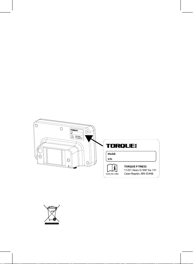
Electrical Specications and Disposal Instructions
Power Requirements: Four (4) AA batteries
Disposal: Waste of electrical and electronic equipment must not
be disposed as unsorted municipal waste. It must be
collected separately, and must be disposed of per local
regulations. Unlawful disposal may cause environmental
pollution.
Remove batteries from console unit and dispose of
batteries and console according to local regulations.

2
M1 Digital Console Assembly Instructions
Assembly Preparation
Unpack all contents, removing all packaging and protective bags. Verify all items
shown below are included and undamaged. A
#2 Phillips screwdriver (not
provided) is required to complete the assembly.
Digital Console
(M5 x 16 Phillips)
Hardware
Assembly and User Instructions AA Batteries (4)
3
1. Insert M1 handles (if they are not currently installed), then tip M1 upright
to rest on handles.
2. Use #2 Phillips screwdriver to remove two (2) screws, two (2) nuts, and
the resistance handle grip; set aside for re-installation in assembly step
3-5.
3. Use #2 Phillips screwdriver to remove six (6) screws and shroud; set
aside for re-installation in assembly step 3-4.
4. From the inside of the shroud, locate the snap hooks holding the cover
plate in place. Squeeze the snap hooks together to release the plate
and remove it from the shroud.
1. Remove Cover Plate
2
1
3
Snap hooks on back side of panel
4

4
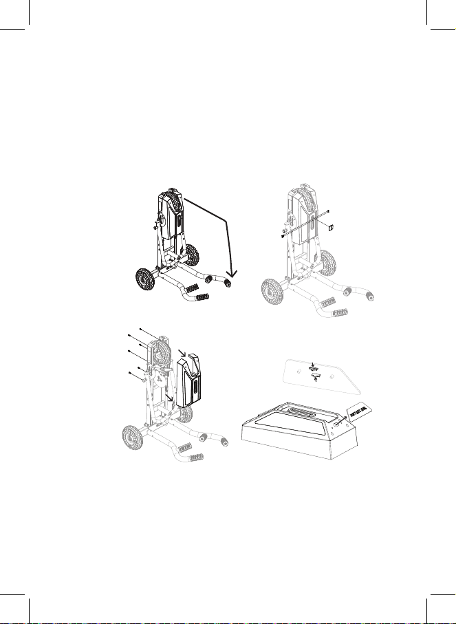
2. Install Batteries and Attach Console
1. On back of console, remove battery cover thumb screw and battery
cover; set aside.
2. Slide out battery carriage and insert batteries in carriage as shown.
3. Replace battery cover and secure to back of console with thumb screw.
4. Feed console wires (quantity 2) through oval hole in shroud (not
shown).
5. Align and secure console to shroud by inserting #2 Phillips screws
(quantity 2) from inside of shroud through holes and into console back.
Tighten with #2 Phillips screwdriver.
12
3
4
5

5
3. Connect Cables, Install Shroud and Handle Grip
1. Lower M1 base back to its standard position on the floor.
2. Balance the console/shroud assembly on the base as shown, then connect the
two (2) cables from mast to cables in base (not shown). One cable pair has 2-pin
connectors; the other pair has 3-pin connectors. Be sure to match them properly
and do not force them together; the connector pairs should snap together easily.
Listen for a “click” to ensure a good connection.
3. Making sure the cables are clear of the internal mechanisms and the edges of the
shroud, carefully lower the console/shroud assembly onto the base.
4. Use #2 Phillips screwdriver to secure shroud to base using the six (6) screws
removed in assembly step 1-3.
5. Place resistance handle grip on handle shaft and use #2 Phillips screwdriver to
secure with two (2) screws and two (2) nuts removed in assembly step 1-2.
6. Calibrate the console (required for proper console function):
a. Press and hold “USER” and “DATA” simultaneously for three seconds to access
the calibration screen.
b. Set the brake lever to “N”, then press “USER” to set the brake position.
c. Move the brake lever to “1”, then press “USER” to set the brake position. Repeat
this step with the brake lever in positions “2” and “3”. The display exits the
calibration screen upon completion of level 3 calibration.
1
5
3
4
2
46
Calibration Screen
DATA
USER
Brake Lever Position
6
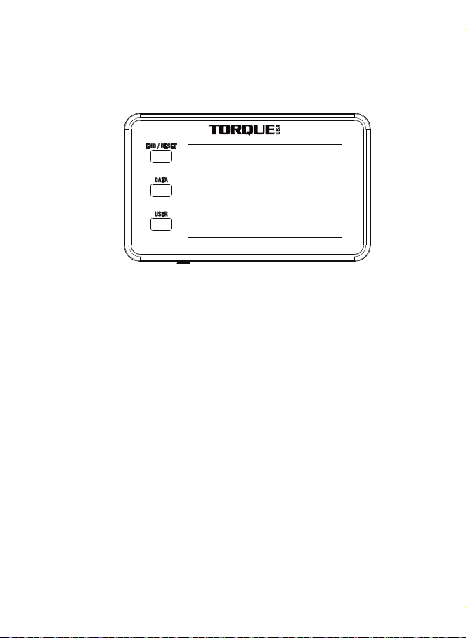
The console features three (3) buttons to control the digital display:
END / RESET Press this button to end a workout and activate the workout summary
display. Press and hold the button for three seconds to reset the console data
to the neutral state or cancel programming.
DATA Press this button during a workout or workout summary to move between
display settings for the bottom half of the screen. The display offers three
display states:
• Calories and Watts
• Distance and Speed
• Total Push Energy and Push Force
During the workout summary, the display alternately shows average and max
values for Watts, Speed, and Push Force.
USER This button manages a multi-user workout. Single users do not use this
button.
Before the workout: Press this button to set the number of users
(1 - 4)
During the workout: Press this button to advance the display for the next user
to begin.
During the workout summary: Press this button to advance the display to see
the next user’s data.
Console Buttons
M1 Digital Console User Instructions

7
The default console values for Units, Beep, and Backlight may be changed if desired.
Follow these steps to verify or change the settings:
1. Press and hold “DATA” and “END” simultaneously for three seconds to access the
Setup screens.
2. Press “DATA” to toggle the units setting between imperial (feet, pounds, and
miles/hour) and and metric meters, kilograms and kilometers/hour). Press “END” to
move to the beep setup screen.
3. Press “DATA” to toggle the beep On or Off. Press “END” to move to the backlight
setup screen.
4. Press “DATA” to toggle the backlight On or Off. Press “END” to save your selections
and return to the main display screen.
Console Setup (Optional)

8
Display
The digital LCD includes the following data at the top of the screen:
USER This field identifies the current user. The default value is 1 (”User 1”). A
multi-user workout can have up to four (4) users.
TIME During a workout, this field displays the elapsed time of the current
User’s workout, actively counting up (in minutes:seconds). The time
displayed is one of two sub-values:
WORK The elapsed time the M1 has been moving (the active User’s
“work”)
REST The elapsed time the M1 has been immobile (the active User’s
“rest”). In a group workout, the Rest Time includes the time
between turns for the user.
During the Workout Summary, the Time field automatically toggles
between total Work time and total time for the user.
The bottom left side of the screen has three alternative displays of cumulative data
for the current user:
TOTAL PUSH Displays the cumulative energy the user has exerted during the
workout,
ENERGY ranging from 0-9999.
CAL Displays the approximate number of calories burned during the
workout (based on a user weight of 150 pounds), ranging from 0-9999.
DISTANCE During a workout, displays the approximate distance the M1 has been
pushed by the user, in feet or meters, from 0 to 9999.
During the Workout Summary, totals for the workout are shown in
these fields.
The bottom right side of the screen has three alternative displays of active (point in
time) data for the current user:
PUSH FORCEDisplays an approximate level of effort (force) the user is applying, in
pounds or kilograms, ranging from 0-999.9.
WATTS Displays the approximate watts currently being generated, ranging
from 0-999.9.
SPEED Displays the approximate current speed, in miles or kilometers per
hour, from 0-99.9.
During the Workout Summary, average and maximum values for the
workout are shown in these fields.

9
Limited Product Warranty
Who is covered
The warranty is valid only to the original purchaser in the United States or
Canada and not transferable to any other person.
What is covered
Torque Fitness warrants that this product is free from defects in materials and
workmanship, when used as intended, in normal conditions and provided
proper care and maintenance as described in the product’s Assembly and User
Instructions. This warranty is good only for authentic, original, legitimate machines
manufactured by Torque Fitness and sold through an authorized agent and used
in the United States or Canada.
Terms
Electronics 3 years
What Is Not Covered
• Damage due to abuse, tampering or modication of the product, failure to
properly follow assembly instructions, maintenance instructions, or safety
warnings as stated in the Product Documentation (Assembly and User
Instructions, etc.).
• Damage due to improper storage or the effect of environmental conditions
such as moisture or weather, misuse, mishandling, accident, natural disasters,
power surges.
• Damage due to normal usage and wear and tear.
• Damage to the nish of the console.
• Shipping charges and if applicable labor for the installation of any parts
shipped to the owner under this warranty.
• This warranty does not extend to any territories or countries outside the United
States and Canada.
Expirations
If the warranty has expired, Torque Fitness may assist with replacements or
repairs to parts and labor, but there will be a charge for these services. Contact
Torque Fitness for information on post-warranty parts and services. Torque
Fitness does not guarantee availability of spare parts after expiration of warranty
period.
International Purchases
If you purchased your machine outside of the United States, consult your local
distributor or dealer for warranty coverage.
For warranty questions or claims, email service@torquetness.com, or call
763-754-7533 (8:30 am – 5:00 CST).
For service and support, contact your dealer, or email service@torquetness.
com, or call
763-754-7533 (8:30 am – 5:00 CST).

Torque Fitness
11201 Xeon Street NW Ste 101
Coon Rapids, MN USA 55448
www.torquetness.com
Toll free: 1-877-TORQUE5 (1-866-664-9894)
or 763-754-7533 (8:30 am – 5:00 CST).
For sales: sales@torquetness.com
For service: service@torquetness.com
© 2022 Torque Fitness. All rights reserved.
P/N 5815901 REV A 11/2022
Table of contents


