manuals.online logo
Brands
  1. Home
  2. •
  3. Brands
  4. •
  5. Toshiba
  6. •
  7. TV
  8. •
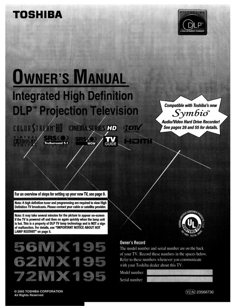
  9. Toshiba HM67 User manual

Toshiba HM67 User manual

This manual suits for next models

1

Other Toshiba TV manuals

Toshiba 13A24 User manual

Toshiba

Toshiba 13A24 User manual

Toshiba 40LV685D User manual

Toshiba

Toshiba 40LV685D User manual

Toshiba 27AF44 User manual

Toshiba

Toshiba 27AF44 User manual

Toshiba 36AX61 User manual

Toshiba

Toshiba 36AX61 User manual

Toshiba 36A11 User manual

Toshiba

Toshiba 36A11 User manual

Toshiba 40PW03G User manual

Toshiba

Toshiba 40PW03G User manual

Toshiba MV14FM4 User manual

Toshiba

Toshiba MV14FM4 User manual

Toshiba 43L3663DG User manual

Toshiba

Toshiba 43L3663DG User manual

Toshiba 14AR21 User manual

Toshiba

Toshiba 14AR21 User manual

Toshiba 46HM84 - 46" Rear Projection TV Quick start guide

Toshiba

Toshiba 46HM84 - 46" Rear Projection TV Quick start guide

Toshiba 19A30 User manual

Toshiba

Toshiba 19A30 User manual

Toshiba CF30F40R User manual

Toshiba

Toshiba CF30F40R User manual

Toshiba 27D46 - 27" CRT TV User manual

Toshiba

Toshiba 27D46 - 27" CRT TV User manual

Toshiba 26HF15 User manual

Toshiba

Toshiba 26HF15 User manual

Toshiba CZ32T31 User manual

Toshiba

Toshiba CZ32T31 User manual

Toshiba 32SL410U Assembly instructions

Toshiba

Toshiba 32SL410U Assembly instructions

Toshiba 32XV635D User manual

Toshiba

Toshiba 32XV635D User manual

Toshiba CZ32V61 User manual

Toshiba

Toshiba CZ32V61 User manual

Toshiba 57H93 User manual

Toshiba

Toshiba 57H93 User manual

Toshiba AV6**D Digital Series User manual

Toshiba

Toshiba AV6**D Digital Series User manual

Toshiba 32SL863B User manual

Toshiba

Toshiba 32SL863B User manual

Toshiba CN36G90 User manual

Toshiba

Toshiba CN36G90 User manual

Toshiba CF32E55 User manual

Toshiba

Toshiba CF32E55 User manual

Toshiba 28ZD06G User manual

Toshiba

Toshiba 28ZD06G User manual

Popular TV manuals by other brands

IKEA UPPLEVA user manual

IKEA

IKEA UPPLEVA user manual

Sony XBR-100Z9D reference guide

Sony

Sony XBR-100Z9D reference guide

Sony Trinitron KV-HR36M90 Service manual

Sony

Sony Trinitron KV-HR36M90 Service manual

JVC AV-14AG16 instructions

JVC

JVC AV-14AG16 instructions

Loewe Table Stand Reference 55 user guide

Loewe

Loewe Table Stand Reference 55 user guide

Panasonic Genus TX-G10 operating instructions

Panasonic

Panasonic Genus TX-G10 operating instructions

Samsung LN26C350D1D Service manual

Samsung

Samsung LN26C350D1D Service manual

BBK LT1516D Service manual

BBK

BBK LT1516D Service manual

Samsung 55S9 B Series Quick setup guide

Samsung

Samsung 55S9 B Series Quick setup guide

Sharp LC-40FI5012E user manual

Sharp

Sharp LC-40FI5012E user manual

Evervue BN185 Operation manual

Evervue

Evervue BN185 Operation manual

North State TV2GO user guide

North State

North State TV2GO user guide

Magnavox PS1980 owner's manual

Magnavox

Magnavox PS1980 owner's manual

Philips 20HF5335D manual

Philips

Philips 20HF5335D manual

Panasonic QuintrixF TX-29AS1D operating instructions

Panasonic

Panasonic QuintrixF TX-29AS1D operating instructions

Samsung 4 Series Quick setup guide

Samsung

Samsung 4 Series Quick setup guide

Panasonic TX-21FG20R Service manual

Panasonic

Panasonic TX-21FG20R Service manual

RCA RNSMU5536 instruction manual

RCA

RCA RNSMU5536 instruction manual

manuals.online logo
manuals.online logoBrands
  • About & Mission
  • Contact us
  • Privacy Policy
  • Terms and Conditions

Copyright 2025 Manuals.Online. All Rights Reserved.

2007 Toshiba DLP
HM67 and HM167
HD
Ready DLP Televisions
TOSHIBA
_at
1_'!r'11i~A
•••••••••••••••••••••••••••
2007 DLP Television
DLP·07·1 Disassembly,
Block
Diagram &Troubleshooting
Course: Servicing the HM67 DLP Televisions
Model Year: 2007
Chassis: DLP67
Models: 50HM67, 57HM67, 65HM67, 57HM117/167,
and
65HM117/167
Purpose: Training Module DLP-07-1 introduces the HM67 DLP Television
by
providing an operational overview, preferred disassembly method
and "Fix-on-first-Call" troubleshooting methods.
Objectives: Upon completion ofthis training module, the technician will:
1.
Become familiar with methods used to analyze basic symptoms
leading to "board level repair
on
the first call".
2.
Develop
an
understanding of the controls
and
inputs associated with
the 2007 DLP Television.
3.
Become familiar with the disassembly ofthese units.
4.
Become familiar with PCB locations
and
their functions as they relate
to general diagrams ofthe units.
Product
Specific Service Manuals:
This training is designed as an aid to the technician in servicing Toshiba products. It is not a replacement for the
appropriate service manual(s). Toshiba service manuals contain product and model specific information and must
be consulted prior to servicing any product.
Product
Safety Precautions:
Product Safety Precautions
are
described in the Toshiba service manual(s) for products and models covered in this
training. All safety precautions and checks must be complied with before returning any product to the customer.
Servicers who defeat safety features
or
fail to perform safety checks may be liable for any resulting damages and
may expose themselves and others to possible injury.
TOSHIBA AMERICA CONSUMER PRODUCTS, LLC
National Service Division -1420B Toshiba Drive -Lebanon,
TN
37087
www.tacpservice.toshiba.com/tacp E-Mail: [email protected]
© 2005 Toshiba America Consumer Products, LLC
2007 Toshiba DLP Television
DLP-07-1
Introduction
Capabilities of the 2007 DLP Televisions:
Screen Resolution:
Screen Sizes:
HDMI Inputs:
Features:
• Fully Integrated -Receives NTSC, ATSC. and QAM cable
signals
in
High Definition.
In
order for these sets to display a
High Definition picture, the set must receive one
of
the
following:
o An "OffAir" (terrestrial)
HD
broadcast.
o
An
HD
cable broadcast.
o An
HD
satellite broadcast.
o
An
HD
input from
an
HD
DVD
unit.
• Limited by the Light Engines capabilities.
o Several Models within the series will contain Ught
Engines capable of processing and reproducing
1080p, while others will except 1080p as
an
HDMI
input but will down convert it to 720p for display
purposes.
. 0 Models ending in just
67
will display 720p.
o Models ending in 167 will display 1080p.
• Three screen sizes (listed by model)
o 50HM67 -50"
o 57HM167 57"
o 65HM67 -65" 65HM167 -65"
• Three HDMI inputs.
o Only HDMI1 can
be
used to input a UVI signal (via
an
adaptor cable).
• The OSD menu must
be
set
to
Analog Audio.
• The audio cables must
be
connected to
the
PC/HDMI-1 audio connectors.
o HDMI 2 &3 are normal
HDMI
inputs.
• Integrated Digital and Analog Tuning.
• Three HDMI Digital
HD
multimedia interfaces.
• Two sets of ColorStream
HD
component inputs.
•
SRSWOW
• Digital Audio Output (Optical connection with Dolby).
• Cable Clear
DNR
(digital noise reduction -Picture).
Figure 1
is
a photo
of
the front
of
the 50HM67, the unit we used for this training module.
DLP-07-1
10f44
2007 Toshiba DLP Television
DLP-07-1
Figure 1
Figure 2
is
a photo
of
the rear jack panel and inputs to the Digital (Seine) module.
Note: The cover plate has been removed from the Smart Card slot for clarity purposes.
Figure 2
Disassembly
Figure 3 is a photo showing screw proximities to aid in removing the back cover.
DLP-07-1
20f44
----
2007 Toshiba DLP Television
DLP-07-1
Figure 3
Once the ten screws are removed from the back cover, we will see a split chassis much
like we have seen in the past. Figure 4 is a photo depicting a split chassis.
Split
Chassis
Figure 4
DLP-07-1
30f44
2007 Toshiba DLP Television
DLP-07-1
Figure 5 is a photo showing the four screws that must be removed to move the Main
chassis and Light Engine chassis'.
Figure 5
Figure 6 shows a wire tie that can be squeezed and removed.
Figure 6
DLP-07-1
40f44
2007 Toshiba DLP Television
DLP-07-1
Figure 7 is a pictorial of how to squeeze the new type wire tie.
Reusable
wire
tie
You
can
pullout
this
tie
by
pushing
from
both
sides
Figure 7
Figure 8 explains the rest of the tie/clip removal.
You
can
now
movill
the
cha1J!.Iis
Remove
",1m
from
more
toward
thlt
,eal'
tv
r..1;)lls0 "lip's
the
mma!ning
tics.
Figure 8
DLP-07-1
50f44
2007 Toshiba DLP Television
DLP-07-1
Board/Function Familiarization
The two chassis sides can now be pulled from the cabinet where complete access will
be available for any necessary troubleshooting. Figure 9 is a graphic layout
of
the Main
side chassis half. This layout is exactly as it appears looking from the top.
HM67 Board Layout
Audio
Out·
Figure 9
Now, let's examine each
of
the boards that comprise our chassis. We will begin by
looking at Figure 10, a photo
of
the entire chassis, taken from a top left viewing angle.
Comparing Figure 10 with Figure
9,
we can see that the photo and graphic
representations are identical. Therefore, as we progress, we will use the graphic
representation for our training purposes.
Using Figures
11
thru 14 we will discuss each individual board.
DLP-07-'1
60f44
•
•
2007 Toshiba DLP Television
DLP-07-1
Figure 10
4
i5il
:;y
~.~
~.·.·:;.·I
~2
;:"f>%
i
':l
~---;-~.,:q
t'l
~"l
'i·
..
~.
~'
\.
".
.
............................
__
.........
_
......
_
..............
_
..................
"
...
-
..
-
·
·
·
·
'1
Input
device
for
all anaiog signals; Video, ColorStream,
RGB,
SNideo, Analog Audio. •
:
•
·
:
Output
deVIce
for
fixed
left
and
Right
Analog Audio. :
·
t
:
Switching
for
an;\!og inputs. ·
•
,
:
,
TV
MicroprocessorfuncUons:
ATSCINTSC tuning.
MTS
Processor, Audio Processor, !
AV
Switching, Digital
light
Engine, Power
to
chassis, !
LED functions, Remote and Front Keyboard commands. !
•
•
:
Audio
processinu
(except final amp). ·
·
:
:
ATSC/NTSC
tuner
on board. ·
,
·
•
~
...
,..
................
"".",,
...
""'
....
_
.........
_
..
_
..
"'.....................................ft·,.
..
"'
..
,.
............
_
.......
""
.....
""
.................
""
..............
__
......................
"'
........
_
......
_
...
_
..
-
...
,..
..................
__
....
~
...........
.
Figure
11
DLP-07-1
70f44
2007 Toshiba DLP Television
DLP-07-1
~-
....
--
..
-
......
-................-
.........
-*""
................
"'
.........................................
--",
...
~
.....
-
.......
-
....
",
.............
""
.....................
""t
. .
/ AID and DIA conversions. i
l :
/ i
I Up
or
Down Converting
81gnals
to accommodate
light
l
I enginecapabilities (720p·1080p). !
Control and Processing
of
all Digital Signals. !
j
i
Developing and Outputting
LVDS
Signals to the light '
I,
engine.
\
\ Control
of
TV Micro
via
lie bus lines. !
i
\
\
\.
Provide
an
Optical Audioand Theater Link output. .
!
;
;
\ Control
SO
card applications. !
\
\Inputdevice
for
3
HDMI
inputs. !
~
~
••
-
......
-
...................
"'
...............................
-
...............
«
....
-
....
-.-
.............
""
.................
""
............................
.
Figure 12
_1T',.·""'*
..
1i'·
.......
·"'·"''''IIO
.......
_IW>~
......
''''
...
--~lf>
.............
1'
#~
.
;t
••
"
Audio
Power AmplifIcation
...
, I
*",.,.
I~
/
Output
to
Speakers
:'
, I
, .
1/1##~
..............
""'/Of
.........
'
...................................
#l
H.Mfi1
eo.wd
~."
-.#
."
•••
Figure
13
DLP-07-1
R
of44
2007 Toshiba DLP Television
DLP-07-1
f
..........
-_
..................................
"'
.....
_-,."'
.......
-
.........
-
....
-_
.......................
-
............
-_
..........
iii
....
..
"''''··-7
,.
-
! Prollides Standby and Operating Voltages
to
char.sls. !
·
; :.
· .
i 5V1. 12V_
$i9,
32V
to
Tuner, 31V
Audio
Vcr;,
,I
• 12VDMD.
and
120VAC
Ballast
Supply.
•
i! 12V_Slg Is stepped
down
or
regulated
On
til"
Mail! il
! Board
to
5V_Vcc_DDR.12V_Audlo.
3.0V. 2.SV. 3.3VO. J
: and 6.nVO. i
: :
: 1
i
5V1
Is stepped
down
on
the Main
board
to
3.3V1 /
·
• •
.
\. ,
!
. .
\ :
\, ,
.
I
,
\ 1
\ i
\\
. HM87 Board
t.ay/ut
.
\\
.
'Ii",-,.
...
\\
•.
~\
\\
,)
"',o'
Figure
14
Fix
on
the
First
Call
Knowing the functions of each board is invaluable in determining what to bring
on
the
service call before leaving the shop. Once this learning curve is mastered.
the
technician can apply a basic troubleshooting flowchart to any symptom that a customer
may describe during
hi:::./her
initial call requesting service.
The key to success
is
to
spend a small amount of time talking to the
custom~r
and
asking the right questions.
During this training,
we
will use basic flowcharts to provide enough information to
accomplish this worthwhile goal.
We will also provide a graphic of the LED "Blink" codes that can
be
helpful
in
determining problem areas
in
the HM67 and HM167 series
DLP
sets.
Dead Set
Figures 15 through 15b are prime examples of a basic flowchart of what the customer
thinks is a "Dead Set".
DLP-07-1
q
of44