Totem 10 User manual

TOTEM ENERGY srl
via Ivrea, 70
10098 Rivoli (To) - Italia
+39 0119579211
User’s Guide
TOTEM 10A -TOTEM 20A MICROCOGENERATORS

User’s Guide | TOTEM 10 - TOTEM 20
2 of 30
1.
Declaration of Conformit .................................................................. 3
2.
General Safet Instructions ................................................................ 4
A.
S mbols Used in the Guide .................................................................. 4
B.
Glossar of Terms and Definitions ........................................................ 4
C.
Safet Instructions .............................................................................. 5
D.
Potential Safet Risks .......................................................................... 7
3.
Product Description ........................................................................... 9
A.
General Information ............................................................................ 9
B.
Product ID........................................................................................ 10
C.
Module Main Components .................................................................. 10
D.
TOTEM - La out of Components ......................................................... 14
E.
Safet Instructions ............................................................................ 15
F.
Size and Overall Dimensions .............................................................. 17
G.
Control Switchboard .......................................................................... 18
H.
Connection Panel .............................................................................. 19
I.
Noise Emissions and Vibrations .......................................................... 20
4.
Use of the Micro Cogenerator .......................................................... 20
A.
Preparing the Unit for Use ................................................................. 20
B.
Operator Panel ................................................................................. 21
C.
Starting and Working Principle ........................................................... 23
D.
Operating Conditions ......................................................................... 24
E.
Fuel Characteristics ........................................................................... 24
F.
User S stem’s Water Characteristics ................................................... 25
G.
Emergenc Stop and Shutdown .......................................................... 26
H.
Calendar .......................................................................................... 26
I.
Diagnostics ....................................................................................... 26
5.
Remote Control ............................................................................... 27
A.
Local Area Network Connection .......................................................... 27
B.
Remote Connection ........................................................................... 28
6.
Maintenance ................................................................................... 29
User’s Guide | TOTEM 10 - TOTEM 20
3 of 30
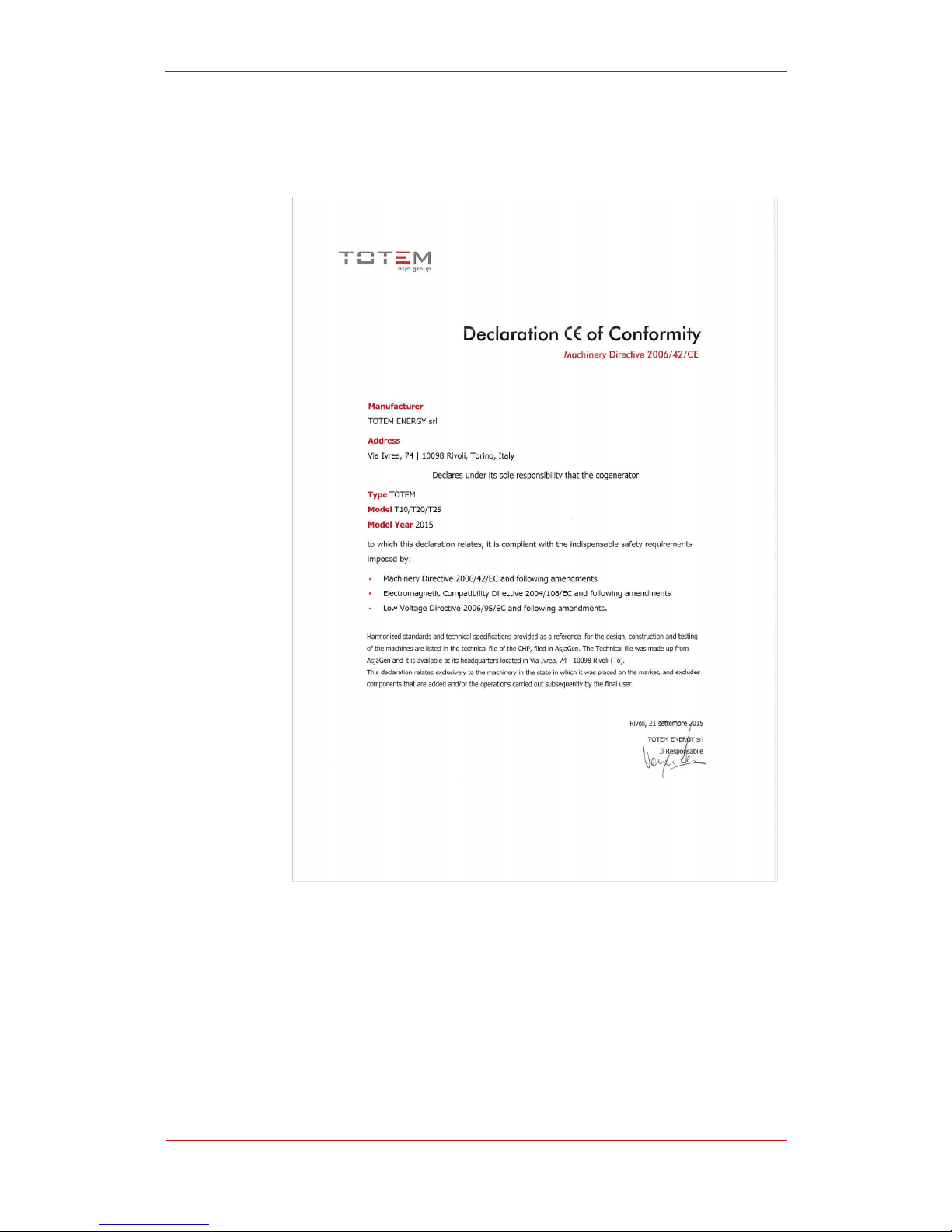
1.
Declaration of Conformit

2.
General Safet
A.
S mbols
B.
Glossar of Terms and Definitions
Machine Operator
specific skills
the operator’s control devices, checking on its proper functioning and reporting an
p
ossible anomal to the Technical Support Service
Qualified
possessing specialist technical expertise in the fields of heating s stems, hot water
production s stems, electrical and electrical energ generating s stems, combustible
gas-
fired plants and ap
engines as well as components thereof. Such professionals must be licensed as
required b the applicable laws in force in the place where the TOTEM® is installed.
Maintenance staff
possessing formall recognized professional skills, trained and authorized b Totem
Energ to carr out maintenance operations on the
Personal
Protective
shall mean the following safet wear and equipment:
PPE must be
starting and maintenance
User’s Guide | TOTEM 10
General Safet
Instructions
S mbols
Used in the Guide
Glossar of Terms and Definitions
Machine Operator
: “Machine Operator” shall mean
an member of
specific skills
who can onl perform simple tasks, namel :
operating the unit b using
the operator’s control devices, checking on its proper functioning and reporting an
ossible anomal to the Technical Support Service
;
Technician: “Qualified Technician”
shall mean a trained professional
possessing specialist technical expertise in the fields of heating s stems, hot water
production s stems, electrical and electrical energ generating s stems, combustible
fired plants and ap
pliances equipped with Otto or Miller
engines as well as components thereof. Such professionals must be licensed as
required b the applicable laws in force in the place where the TOTEM® is installed.
Maintenance staff
: “Maintenance staff”
shall mean a Qualified Technician
possessing formall recognized professional skills, trained and authorized b Totem
Energ to carr out maintenance operations on the
TOTEM®
units
Protective
Equipment PPE): “
personal protective equipment
shall mean the following safet wear and equipment:
hearing protections
(earmuffs or earplugs) for the hearing protection of
workers operating on the TOTEM® unit in operation with the sound
insulation panels removed (which
can be done solel for
troubleshooting or maintenance purposes).
protective gloves and goggles when working with batter acid, gl col
and engine lubricant oil;
safet shoes;
dielectric face shield and gloves when carr ing out operations on
energized electrical parts.
PPE must be
worn b Maintenance staff at all times when
performing
starting and maintenance
activities on the TOTEM®.
[Information]
This s mbol indicates important information related to
the use of the equipment.
[Warning]
This s mbol indicates operating procedures whose
incorrect
performance can seriousl damage the equipment.
[Danger]
This s mbol indicates operating procedures whose incorrect
performance can cause injur or even death.
User’s Guide | TOTEM 10
- TOTEM 20
4 of 30
an member of
staff with no
operating the unit b using
the operator’s control devices, checking on its proper functioning and reporting an
shall mean a trained professional
possessing specialist technical expertise in the fields of heating s stems, hot water
production s stems, electrical and electrical energ generating s stems, combustible
pliances equipped with Otto or Miller
-c cle endothermic
engines as well as components thereof. Such professionals must be licensed as
required b the applicable laws in force in the place where the TOTEM® is installed.
shall mean a Qualified Technician
possessing formall recognized professional skills, trained and authorized b Totem
units
.
personal protective equipment
” (PPE)
(earmuffs or earplugs) for the hearing protection of
workers operating on the TOTEM® unit in operation with the sound
can be done solel for
protective gloves and goggles when working with batter acid, gl col
dielectric face shield and gloves when carr ing out operations on
performing
installation,
This s mbol indicates important information related to
This s mbol indicates operating procedures whose
performance can seriousl damage the equipment.
This s mbol indicates operating procedures whose incorrect

C.
Safet Instructions
If ou smell gas odor:
If ou smell products of combustion:
If ou
Unit:
Installation, calibration and modification of the gas feed
performed b a Qualified Technician abiding b all applicable national and local
standards as well as b the instructions provided in this Guide.
Installation, calibration or
performed b a Qualified Technician abiding b all applicable national and local
standards as well as b the instructions provided in this Guide.
Installation, calibration or
b a Qualified Technician abiding b all applicable national and local standards
as well as b the instructions provided in this Guide.
It is mandator to connect the exhaust gas evacuation line of the appliance to
an exhaust gas
requirements in force in the place where the TOTEM® unit is installed. Failure
to compl with said rule poses a serious risk to human and animal safet .
According to the provisions for use,
installed unit in good condition and to ensure the safe and reliable functioning
User’s Guide | TOTEM 10
Safet Instructions
If ou smell gas odor:
turn our gas suppl valve off;
ventilate the room;
do not operate an electrical device or appliance, including cell phones;
leave the premises and call a Qualified T
echnician or the gas utilit
compan immediatel from a different location. If the are unavailable
or in case of an emergenc , call the loc
al Fire Brigade;
if the room is equipped with a gas leak detection s stem, please report
an possible malfunctioning of said active safet equipment.
If ou smell products of combustion:
turn the appliance off;
ventilate the room;
call a Qualified Technician;
if the room is equipped with a smoke/carbon monoxide detection
s stem, please report an possible malfunctioning of said active safet
equipment.
see water, gl col, oil, or other
fluids’ spills on the floor or near
turn the unit off;
call a Qualified Technician;
shut off the User s stem’s circuits, if
an , e.g. water or gas suppl
Installation, calibration and modification of the gas feed
performed b a Qualified Technician abiding b all applicable national and local
standards as well as b the instructions provided in this Guide.
Installation, calibration or
modification of the electrical s stem must be
performed b a Qualified Technician abiding b all applicable national and local
standards as well as b the instructions provided in this Guide.
Installation, calibration or
modification of the water s st
em must be performed
b a Qualified Technician abiding b all applicable national and local standards
as well as b the instructions provided in this Guide.
It is mandator to connect the exhaust gas evacuation line of the appliance to
an exhaust gas
evacuation duct built in compliance with all applicable legal
requirements in force in the place where the TOTEM® unit is installed. Failure
to compl with said rule poses a serious risk to human and animal safet .
According to the provisions for use,
the user has an obligation to keep the
installed unit in good condition and to ensure the safe and reliable functioning
User’s Guide | TOTEM 10
- TOTEM 20
5 of 30
do not operate an electrical device or appliance, including cell phones;
echnician or the gas utilit
compan immediatel from a different location. If the are unavailable
al Fire Brigade;
if the room is equipped with a gas leak detection s stem, please report
an possible malfunctioning of said active safet equipment.
if the room is equipped with a smoke/carbon monoxide detection
s stem, please report an possible malfunctioning of said active safet
fluids’ spills on the floor or near
the Totem
an , e.g. water or gas suppl
Installation, calibration and modification of the gas feed
s stem must be
performed b a Qualified Technician abiding b all applicable national and local
standards as well as b the instructions provided in this Guide.
modification of the electrical s stem must be
performed b a Qualified Technician abiding b all applicable national and local
standards as well as b the instructions provided in this Guide.
em must be performed
b a Qualified Technician abiding b all applicable national and local standards
It is mandator to connect the exhaust gas evacuation line of the appliance to
evacuation duct built in compliance with all applicable legal
requirements in force in the place where the TOTEM® unit is installed. Failure
to compl with said rule poses a serious risk to human and animal safet .
the user has an obligation to keep the
installed unit in good condition and to ensure the safe and reliable functioning

of the micro cogenerator and o
relevant activities performed b Qualified Technicians.
The
user has an obligation to have the appliance maintained b a Qualified
Technician in accordance with the provisions of this Guide and ensuring
compliance with all applicable domestic and International standards.
TOTEM ENERGY
animals that ma arise from incorrect installation or bad maintenance.
Before switching the unit on, alwa s ensure that all protective panels and
guards have been properl mounted to avoid risks to the safet of personne
Do not obstruct,
Do not use or store an
flam
mable materials in the same room
installed.
When
installed.
The micro cogenerator, an
for its
detectors, pane
room etc.) must not be tampered with, modi
reason
ma
damage, including
This booklet is an integral and fundamental part of the micro cogenerator and
it must be carefull kept b the user for future reference. In the event of a
change of ownership of the micro cogenerator or of the premises where it is
in
stalled, please ensure that this booklet is handed over to the new user.
This booklet contains up
issued, without prejudice to possible amendments or technical updates.
Since our products are const
pictures, process descriptions and technical data.
If ou wish to request the most updated version of this document, to suggest
improvements or report an discrepanc , please contact the compan .
This mi
designed for, namel , the combined production of:
User’s Guide | TOTEM 10
of the micro cogenerator and o
f all s stems connected thereto, having the
relevant activities performed b Qualified Technicians.
user has an obligation to have the appliance maintained b a Qualified
Technician in accordance with the provisions of this Guide and ensuring
compliance with all applicable domestic and International standards.
TOTEM ENERGY
shall not be held liable for
an damage to people, things or
animals that ma arise from incorrect installation or bad maintenance.
Before switching the unit on, alwa s ensure that all protective panels and
guards have been properl mounted to avoid risks to the safet of personne
Do not obstruct,
not
even partiall , the suction duct and exhaust pipe ends.
Do not use or store an
hazardous materials, such as
explosive, combustible or
mable materials in the same room
where the micro cogenerator is
installed.
When
the unit
is in operation, do not sta in the room
installed.
The micro cogenerator, an
auxiliar components
thereof, the s stems
for its
functioning (GAS, water, power, shut-
off devices, firefighting
detectors, pane
ls, switchboards, components of the Totem Unit’s
room etc.) must not be tampered with, modi
fied or otherwise
reason
whatsoever. Failure to compl with this provision
ma cause injuries or
damage, including
severel , people, animals or things.
This booklet is an integral and fundamental part of the micro cogenerator and
it must be carefull kept b the user for future reference. In the event of a
change of ownership of the micro cogenerator or of the premises where it is
stalled, please ensure that this booklet is handed over to the new user.
This booklet contains up
-to-
date information referring to the date it has been
issued, without prejudice to possible amendments or technical updates.
Since our products are const
antl updated, slight differences ma be found in
pictures, process descriptions and technical data.
If ou wish to request the most updated version of this document, to suggest
improvements or report an discrepanc , please contact the compan .
This mi
cro cogenerator must be used solel for the purpose it was expressl
designed for, namel , the combined production of:
hot water in domestic and/or industrial closed-
circuit water s stems;
low voltage (400 V
olts) power for net metering, feed
self consumption.
User’s Guide | TOTEM 10
- TOTEM 20
6 of 30
f all s stems connected thereto, having the
user has an obligation to have the appliance maintained b a Qualified
Technician in accordance with the provisions of this Guide and ensuring
compliance with all applicable domestic and International standards.
an damage to people, things or
animals that ma arise from incorrect installation or bad maintenance.
Before switching the unit on, alwa s ensure that all protective panels and
guards have been properl mounted to avoid risks to the safet of personne
l.
even partiall , the suction duct and exhaust pipe ends.
explosive, combustible or
where the micro cogenerator is
is in operation, do not sta in the room
where the unit is
thereof, the s stems
needed
off devices, firefighting
equipment,
ls, switchboards, components of the Totem Unit’s
equipment
fied or otherwise
altered for an
ma cause injuries or
This booklet is an integral and fundamental part of the micro cogenerator and
it must be carefull kept b the user for future reference. In the event of a
change of ownership of the micro cogenerator or of the premises where it is
stalled, please ensure that this booklet is handed over to the new user.
date information referring to the date it has been
issued, without prejudice to possible amendments or technical updates.
antl updated, slight differences ma be found in
If ou wish to request the most updated version of this document, to suggest
improvements or report an discrepanc , please contact the compan .
cro cogenerator must be used solel for the purpose it was expressl
circuit water s stems;
olts) power for net metering, feed
-in to the grid or

TOTEM ENERGY
for an damages arising from the incorrect installation or use of the unit and, in
an case
instructions or with all applicable national and local laws.
D.
Potential
Risk
related to Mechanical
Injuries from mechanical
guards protecting the micro cogenerator’s moving parts
Said activities must,
specificall for said purpose and wearing the appropri
Risk related to Electrical Hazards
Electrical injuries can occur when safet devices are removed from the s stem,
the
control
Moreover, modifications of the existing
hazards if
performed b unauthorized
Said activities must,
specificall for said purpose and wearing the appropriate PPE.
Risk related to Thermal Hazards
During regular functi
high temperatures.
with frame panels properl mounted, thus preventing access to hot components.
Onl
authorized
Risk related to Noise Hazards
In regular op
the frame’s heat
emissions.
Risk
related to Vibration Hazards
The TOTEM® unit is fitted with suitabl sized anti
vibration transmission to the structures and installations connected thereto.
The removal
exhaust fumes line and the heating
Risk related to Electromagnetic Radiation/Waves Hazards
The TOTEM
to
electromagnetic
as nchronous generator can cause disturbances temporaril affecting the functioning
of electro-
medical
in close proximit to it.
Risk related to Contact with Hazardous Materials and Substances
On the inside, the TOTEM® module contains chemicals that are essential
proper functioning.
User’s Guide | TOTEM 10
TOTEM ENERGY
shall bear no liabilit -
either contractual or extra
for an damages arising from the incorrect installation or use of the unit and, in
an case
whatsoever
, from failure to compl with the manufacturer’s
instructions or with all applicable national and local laws.
Potential
Safet Risks
related to Mechanical
Hazards
Injuries from mechanical
hazards
can occur when the safet devices
guards protecting the micro cogenerator’s moving parts
-
are removed
Said activities must,
therefore, be performed sole
l b the Maintenance
specificall for said purpose and wearing the appropri
ate PPE.
Risk related to Electrical Hazards
Electrical injuries can occur when safet devices are removed from the s stem,
control
switchboard, or from the ignition s stem.
Moreover, modifications of the existing
power suppl s stem
performed b unauthorized
personnel.
Said activities must,
therefore, be performed solel b
Maintenance staff
specificall for said purpose and wearing the appropriate PPE.
Risk related to Thermal Hazards
During regular functi
oning, some of the TOTEM®’s inner components
high temperatures.
The entire appliance must, therefore, work under safe conditions
with frame panels properl mounted, thus preventing access to hot components.
authorized
Maintenance staff are authorized to remove the
unit’s panels.
Risk related to Noise Hazards
In regular op
eration, the whole TOTEM® unit
must work under safe conditions with
the frame’s heat
-insulation panels properl mount
ed, which lowers the Unit’s noise
related to Vibration Hazards
The TOTEM® unit is fitted with suitabl sized anti
-
vibration mounts to reduce
vibration transmission to the structures and installations connected thereto.
The removal
of anti-vibration fittings from connec
tions with the gas
exhaust fumes line and the heating
s stem is strictl forbidden.
Risk related to Electromagnetic Radiation/Waves Hazards
The TOTEM
unit complies with Directive
2004/108/EC
electromagnetic
compatibilit . However, the electroma
gnetic fields from the
as nchronous generator can cause disturbances temporaril affecting the functioning
medical
devices such as, for example,
pacemakers or hearing aids located
in close proximit to it.
Risk related to Contact with Hazardous Materials and Substances
On the inside, the TOTEM® module contains chemicals that are essential
proper functioning.
User’s Guide | TOTEM 10
- TOTEM 20
7 of 30
either contractual or extra
-contractual –
for an damages arising from the incorrect installation or use of the unit and, in
, from failure to compl with the manufacturer’s
can occur when the safet devices
- panels or
are removed
.
l b the Maintenance
staff trained
Electrical injuries can occur when safet devices are removed from the s stem,
from
ma cause serious
Maintenance staff
trained
oning, some of the TOTEM®’s inner components
ma reach
The entire appliance must, therefore, work under safe conditions
with frame panels properl mounted, thus preventing access to hot components.
unit’s panels.
must work under safe conditions with
ed, which lowers the Unit’s noise
vibration mounts to reduce
vibration transmission to the structures and installations connected thereto.
tions with the gas
suppl grid, the
2004/108/EC
relating
gnetic fields from the
as nchronous generator can cause disturbances temporaril affecting the functioning
pacemakers or hearing aids located
Risk related to Contact with Hazardous Materials and Substances
On the inside, the TOTEM® module contains chemicals that are essential
to its

User’s Guide | TOTEM 10 - TOTEM 20
8 of 30
Namel , it contains substances such as batter acid, fresh/spent lube oil and gl col-
water mixtures.
In the presence of spills outside the TOTEM® unit, an direct contact of these
substances with skin and e es must be avoided at all times.
In the event that ou come into contact with these chemicals, ou must thoroughl
wash the affected bod parts and seek medical advice if necessar , bringing the
relevant Product Safet Data Sheet with ou. Said substances ma even be hot and
cause skin burns.
When in operation, the TOTEM module also produces a constant flow of exhaust
fumes.
In the event of exhaust fumes build-up or leaks from the exhaust gas evacuation
s stem, leave the area immediatel and switch off the module if possible.
Based on the standards in force in the TOTEM®’s place of installation, ou ma also
be required to install a CO/CH
4
gas detector in the module’s room.
The TOTEM alread has an incorporated CH
4
leak detector. Please contact our
Technical Support Service for the detector’s periodic calibration.
Risk related to Slip, Trip and Fall Hazards
Following breakdown or malfunctioning, lubricant oil, water-gl col fluids or batter
acid leaks ma occur, making the floor slipper thus creating a risk for falls.
Said spills must be readil contained and whenever possible disposed of according to
the relevant laws in force.
Risk related to Emergenc stop/Emergenc shutdown
The TOTEM® module is designed to stop immediatel following the activation of one
or more external safet devices connected to it.
Risk related to Power Suppl Interruption
The TOTEM® is designed to enable an immediate safe stop function in the event of
an interruption of the mains power suppl . A suitable interface protection device –
not supplied b TOTEM ENERGY - approved based on the applicable standards in the
module’s place of installation can implement the module’s disconnection from power
suppl whenever the standards of applicable regulations are not met.
Risk related to Control Switchboard malfunction/failure
The TOTEM® module is designed to enable an immediate safe stop in case of
control switchboard malfunction or failure.
Risk from Breakdown during Regular Operation
If kept intact, used for the purpose it was designed for ensuring compliance with the
technical parameters set b TOTEM ENERGY as well as properl maintained, the
TOTEM® is designed to work under conditions that are full safe for machine
operators and s stems connected to it.
Hazards from Use in Environments at Risk of Fire/Explosion - EX
The TOTEM® is not intended for use in environments at risk of fire or explosion (Ex).
Do not keep or store materials that ma increase the risk of explosion or fire in the
room where the TOTEM® is installed.

User’s Guide | TOTEM 10 - TOTEM 20
9 of 30
3.
Product Description
A.
General Information
This User’s Guide is intended to provide the necessar information for the use of
TOTEM units. TOTEM micro cogeneration units are appliances that allow for the
combined production of electricit and heat at the user’s site, thus optimizing the use
of the fuel’s primar energ and reducing grid distribution and separate generation
losses.
CHP units, indeed, can be easil integrated into an technological environment,
enabling fulfillment of the heating requirements of different users in a variet of
sectors:
hospitalit ;
wellbeing;
catering;
health-care;
housing;
public;
agri-food;
distribution chains.
Using a micro cogeneration unit allows to achieve significant economic savings and
environmental benefits.
The unit consists of an endothermic engine originall devised for the automotive
industr , coupled to an as nchronous generator.
The heat produced in the endothermic engine’s combustion process is almost full
recovered b means of a high-efficienc heat exchangers s stem and made available
to users as hot water.
Thanks to its modern propellers manufactured b FCA, speciall engineered to run on
gas and optimized to work under stead -state, the unit allows for optimized
performance and longer maintenance intervals. Moreover, its modern Euro 6
technolog enables a significant reduction of nitrogen oxides - NO
x
- and carbon
monoxide - CO - emissions as compared to conventional condensing boilers.
TOTEM® units’ compact size and versatilit allows installation in tight equipment
rooms and their use on existing premises, including with environmental or
architectural constraints.
Its control s stems allow to monitor and log data for power and heating load profiles,
including remotel . Moreover, it enables service staff to monitor an alarm signal
detected thus enabling emergenc service in case of breakdown or malfunctioning.

User’s Guide | TOTEM 10 - TOTEM 20
10 of 30
B.
Product ID
Each TOTEM® micro cogeneration unit is fitted with a special plate providing all
details for its identification.
C.
Module Main Components
Ever TOTEM® module is the result of painstaking engineering research and
selected technological solutions combining high qualit materials from specialist
suppliers. A detailed description of the module’s main components is provided in the
following sections.
-Endothermic Engine
FCA Fire 1.4 51 kW Bifuel Euro 6, four stroke, Otto c cle endothermic engine, fuel
feeding s stem fitted with a Venturi and throttle for fuel injection adjustment; fuel
injection is governed b a stepper motor.
Engine speed for the TOTEM® module 10 is set at 1,500 revs/minute.
Engine speed for the TOTEM® module 20 is set at 3,000 revs/minute.
Displacement cm
3
1368
Maximum shaft power kW 51
Maximum Output Torque 104 Nm@3250 RPM
Arrangement / Number of C linders L-NA / 4
Vlaves per c linder 2

User’s Guide | TOTEM 10 - TOTEM 20
11 of 30
Compression ratio 11 : 1
Oil Pressure at 1,500 revs bar > 1.8
Oil Pressure at 3,000 revs bar > 3.5
Crankcase Cast Iron
C linder head Steel
Engine weight kg 88
-Asynchronous Generator
TOTEM 10 ASYNCHRONOUS GENERATOR - TECHNICAL FEATURES
Rated power kW 12
Electric power output kW 10
Pole number 4 - 1500 RPM
Rotor Squirrel cage
Cooling s stem Liquid
T pe of cooling fluid water + gl col (max 30%)
Cooling circuit max pressure bar 3
Coolant max flow rate l/h 4000
Max pressure drop with max flow rate bar 0.5
Coolant temp. range °C 30 - 75
H draulic In/Out threading/coupling size inch 1"
Installation environment temp. range °C -20°C +60
Mechanical Design B3/B5 (foot and flange mounting)
Direction of axis horizontal
Terminal box position
On top, with cable exit holes on
the back
Effiienc 92.7 (Efficienc class: IE3)
Power suppl - Voltage - Frequenc Three-phase - 400V - 50 Hz
Insulation/Dut class H/S1 – continuous dut
Rated power factor >0.81
Winding connection Delta/W e 400/690 V
Height of axis mm 160
Shaft diameter mm 42
Length mm 620 (shaft excluded)
Shaft length mm 110
TOTEM 20 ASYNCHRONOUS GENERATOR - TECHNICAL FEATURES
Rated power kW 22
Electric power output kW 20
Pole number 2 - 3000 RPM
Rotor Squirrel cage
Brushless
Cooling s stem Liquid
T pe of cooling fluid water + gl col (max 30%)
Cooling circuit max pressure bar 3

User’s Guide | TOTEM 10 - TOTEM 20
12 of 30
Coolant max flow rate l/h 4000
Max pressure drop with max flow rate bar 0.5
Coolant temp. range °C 30 - 75
H draulic In/Out threading/coupling size Inch 1"
Installation environment temp. range °C -20°C +60
Mechanical Design B3/B5 (foot and flange mounting)
Direction of axis horizontal
Terminal box position
On top, with cable exit holes on
the back
Effiienc 92.7 (Efficienc class: IE3)
Power suppl - Voltage - Frequenc Three-phase- 400V - 50 Hz
Insulation/Dut class H/S1 – continuous dut
Rated power factor >0.81
Winding connection Delta/W e 400/690 V
Height of axis mm 160
Shaft diameter mm 42
Length mm 620 (shaft excluded)
Shaft length mm 110
Compliance with standards:
2006/42/EC Machiner Directive;
2006/95/EC Low Voltage Directive;
2004/108/EC EMC Directive;
IEC EN 60034;
1997/23/EC Directive.
-Heat Recovery System
The TOTEM® unit is equipped with a high performance in-built heat exchange
s stem that can recover heat energ from the gen set, the engine water and oil
circuits, and exhaust fumes. The s stem does not include an heat dissipator device,
therefore, it is onl activated following heat demand.
Heat is recovered b means of the following equipment:
As nchronous generator: the heat recover s stem is incorporated in
the gen set canop . Please see the generator features section.
Engine Oil: AISI 316L stainless steel water/oil brazed plate heat
exchanger
Engine water: AISI 304 stainless steel brazed plate heat exchanger
Exhaust gases: AISI 304 stainless steel water/fumes tube bundle heat
exchanger.
The engine water circuit is governed b a high-efficienc circulator pump having the
following technical features:
Power suppl V 230
Frequenc Hz 50
Max. current A < 2

User’s Guide | TOTEM 10 - TOTEM 20
13 of 30
Minimum inlet pressure 0.1 bar with fluid at 95°C
Fluid temperature °C -10 to + 95
Protection grade
IP X2D
Insulation class H
Equipment class I
The TOTEM’s internal circuit size, flow rates, temperature deltas and circuit pressure
values have been carefull calculated and set upon design.
-Exhaust Treatment and Discharge Line
Exhaust gases from the endothermic engine are conve ed along the treatment and
cooling line before being expelled. The exhaust discharge line comprises a 4-1
manifold, a coaxial exchanger, a three-wa catal st, a tube bundle exchanger for
heat recover and an in-built silencer.
The 4-1 manifold conve s exhaust gases from the 4 engine c linders into the
exhaust duct. It is equipped with a lambda sensor for injected mass control as well
as with a sensor checking gas temperature right at the engine outlet.
The manifold is efficientl insulated so as to minimize heat dispersion along this
section. Gases then go through the coaxial heat exchanger where a first cooling
stage takes place, after which the are sent to the three-wa catal st where
emissions are lowered. The ceramic substrate catal st simultaneousl reduces CO,
NO
x
and HC emissions. It is fitted with a sensor at the inlet to check the right
operating temperature for the catal st, plus a lambda sensor downstream for a
second level titration control. The catal st is thermall insulated, too. The gases
leaving the catal st reach the tube bundle exchanger where the are cooled down
until condensation occurs (T<70°C).
Before being discharged, gases go through an exhaust gas silencer, specificall
devised to lower the noise emissions from the micro-cogenerator for the given rev
number.
-Electrical and Control Switchboard
The Electrical Switchboard complies with current applicable standards and it contains
all the electrical safet devices as well as all control devices governing the unit’s
functioning.
The TOTEM is governed b 3 control units:
ECU (Engine Control Unit): manufactured b Magneti Marelli, it governs
control of the endothermic engine. The control unit is set to work under
stead state conditions and it interfaces through CANbus s stem with
the MCU. It is located inside the unit’s enclosure;
MCU (Machine Control Unit) “Ar a”: developed to fit specific TOTEM
ENERGY requirements, it governs the control and operation of the
TOTEM® unit through an interface with the ECU via CANbus and with
the Gatewa via Modbus protocol. Also, it is connected to a multi-
function multimeter that conforms to a 0.5s accurac class in
compliance with IEC 62053-22 standards. It is located inside the unit’s
enclosure.

User’s Guide | TOTEM 10 - TOTEM 20
14 of 30
Gatewa : unit for data communication to external networks. It governs
control of the HMI (Human-Machine Interface), data transmission to
the Operator Panel consisting of a 7’’ LCD touchscreen monitor, the in
Cloud remote control platform and to external SCADAs, if an . It
communicates via LAN, Wi-Fi and GSM according to modBus TCP
standards. It is found inside the Electrical Switchboard.
-Frame and Panels
Frame with self-supporting base, made of press-bent steel panels. Panels are
powder-coated with pol ester-based coating.
D.
TOTEM - La out of Components
1. Enclosure air vent
2. ARYA control unit
3. Water cooled s nchronous generator
4. Engine water circulator pump
5. Spent oil tank
6. Thermostatic valve
7. Water to water plate heat exchanger
8. Condensate collector tra
9. FIAT FIRE endothermic engine
10. Zero governor valve
11. Water tra
12. Methane gas safet detector
1
2
5
3
4
11
12
6
9
10
8
7

User’s Guide | TOTEM 10 - TOTEM 20
15 of 30
13. Engine air filter
14. Safet frame structure temperature sensor
15. Exhaust silencer
16. Exhaust manifold
17. Oil filter
18. Fumes to water tube bundle heat exchanger
19. Water to oil plate heat exchanger
20. Marelli three-wa catal st
21. Water to fumes coaxial heat exchanger
22. Fresh oil tank
23. Marelli ECU
24. Engine air suction snorkel
E.
Safet Instructions
The TOTEM is equipped with EN ISO 13849 compliant safet s stems so as to
protect machine operators and maintenance staff against hazards linked to the
micro-cogenerator operation.
Risk anal sis has identified the following hazards:
Exhaust gas emissions
Lack of water flow
Spark advanced with temperature increase
Methane gas leak
The s stem is composed of a chain of safet sensors: an electromechanical
thermostat, a methane gas sensor, and an emergenc pushbutton.
Methane gas leakage hazard
The TOTEM is fitted with a catal thic methane gas sensor for gas leaks. The sensor
features a two-threshold calibration that trigger safet s stem activation when gas
leaks are detected inside the unit’s enclosure. The first threshold value is set to 20%
of LEL. Values exceeding threshold are sent to the ARYA PLC that will command the
13
14
17
15
16
23
24
18
21
22
20
19

User’s Guide | TOTEM 10 - TOTEM 20
16 of 30
unit to turn off thus restoring safet conditions. The second threshold value is set to
50% of LEL, exceeding of this values is reported directl to the safet rela that is
actuated even in the event of PLC malfunctioning, closing the gas suppl valve and
turning the unit off.The electrical switchboard terminal block includes a contact for
connection to the natural gas solenoid of the central heating s stem. In the event of
a gas leak, the rela opens this circuit, too, b commanding valve closure.
Exhaust Gas Emission Hazard, Lack of Water Flow Hazard, Timing variation
Hazard
The above mentioned occurrences can pose a danger b causing an increase in
temperature which ma cause some of the unit’s parts to become hot thus putting
the operator at risk of burns, or b causing a discharge of exhaust gases that
upstream of the catal st feature a high carbon monoxide content.
These anomalies can be detected b a safet thermostat fitted inside the unit’s
enclosure and calibrated to actuate the emergenc rela upon reaching 75°C, which
willl switch the unit off. This is a certified s stem guaranteeing high reliabilit even in
the event of a failure of all other control s stems fitted onto the TOTEM.
Emergency Pushbutton
The Operator Panel features an emergenc pushbutton that can be pressed in the
event of an risk situation. The emergenc pushbutton actuates the emergenc rela
that will switch the micro cogenerator off thus restoring safet .
In order to ensure proper functioning of the safet devices and, consequentl ,
Totem’s operation under full safe conditions, the following requirements must
mandatoril be met upon installation:
-The central heating s stem solenoid must be connected to the speciall
devised terminal block located on the TOTEM electrical switchboard;
-Proper room ventilation – at least 600 m
3
/h must be ensured or,
alternativel , enough windows must be provided in the room so as to
ensure an equivalent ventilation rate according to volumes, or a CO sensor
must be installed in the central heating s stem.
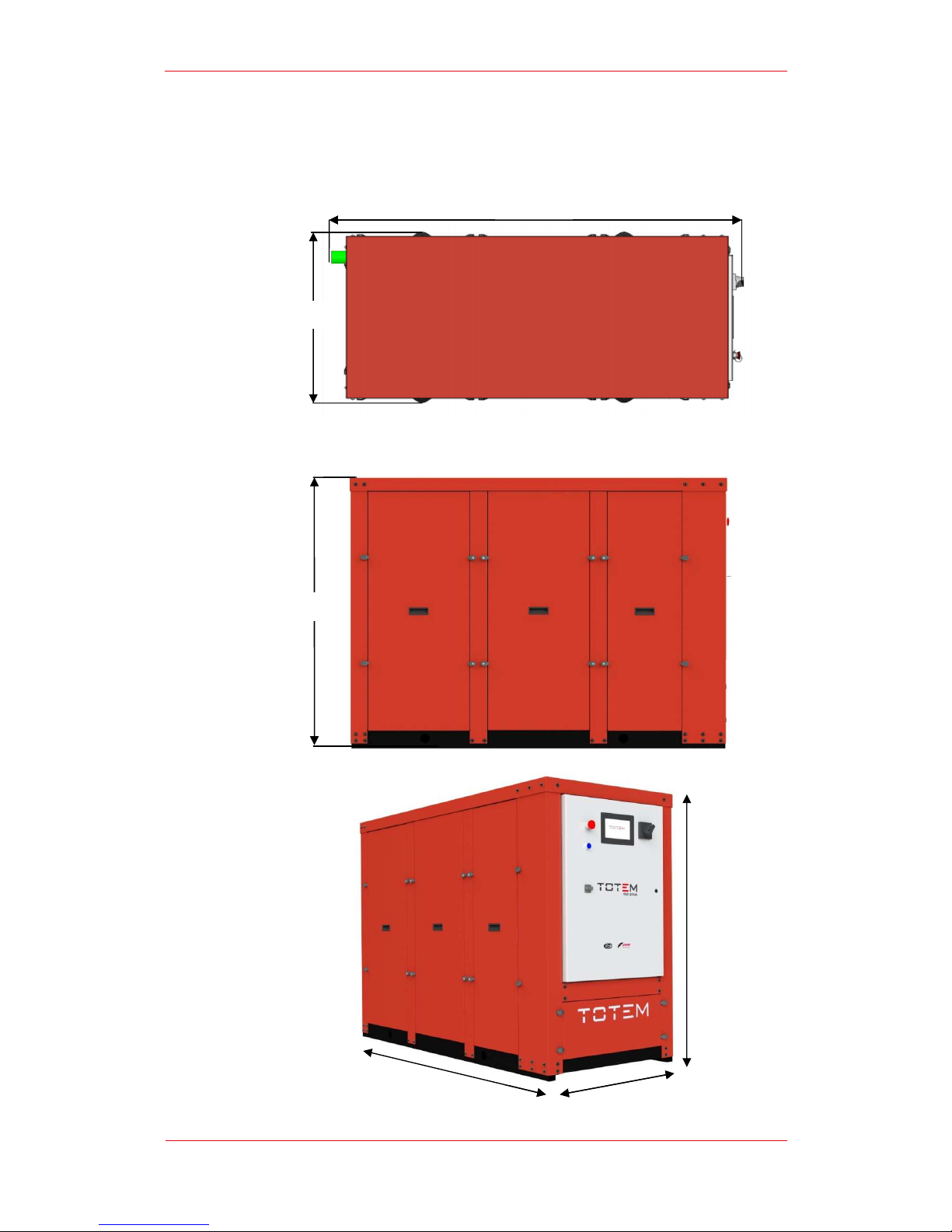
F.
Size and
770 mm
1.280 mm
User’s Guide | TOTEM 10
Size and
Overall Dimensions
1,810 mm
1,810 mm
770 mm
User’s Guide | TOTEM 10
- TOTEM 20
17 of 30
1.
280
mm
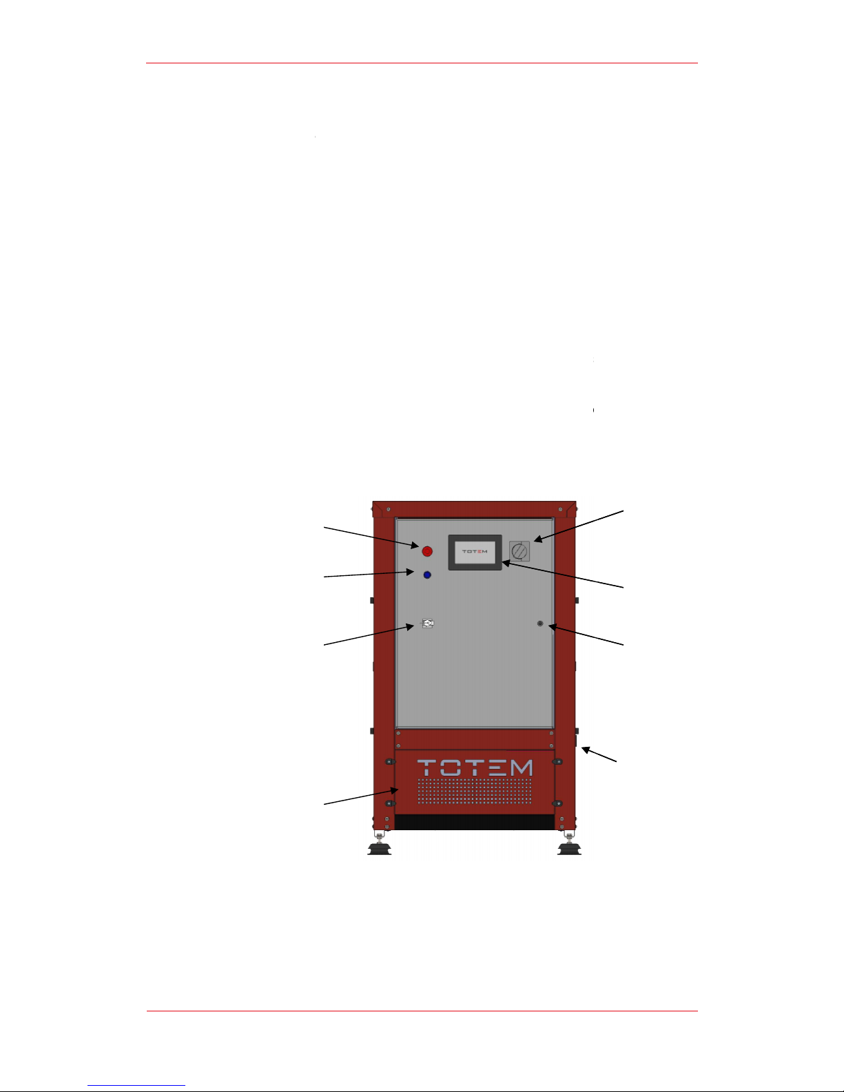
G.
Control Switchb
Machine Operators can operate the machine solel b using the controls available on
the control
remains strictl forbidden due to the presence of energized and hot parts.
The Control switchb
G
E
C
B
User’s Guide | TOTEM 10
Control Switchb
oard
Machine Operators can operate the machine solel b using the controls available on
the control
switchboard; acces
s to the inside of the Control switch
remains strictl forbidden due to the presence of energized and hot parts.
The Control switchb
oard features the following control devices:
Main Switch (A): b operating the Main Switch
, an so
suppl is interrupted and the unit i
s disconnected from the power grid
Emergenc pushbutton (B):
in the event of an emergenc , the unit can
be switched off b pressing the emergenc pushbutton;
Emergenc rela manual reset pushbutton (C):
if the unit is switched
off b means of the emergenc pushbutton or following activation of
one of the alarms along the safet chain (high temperature or methane
leak) , the emergenc rela must be manuall reset b pressing the
reset button before restarting the unit;
Operator Panel (D): it consists of a LCD
7” touchscreen
displa s all the unit’s operating info and enabling operators to enter all
relevant commands;
LAN connection (E): the LAN port enables con
nection to other devices
providing access the operator panel.
A: Main Switch
B: Emergenc Pushbutton
C: Emergenc Rela Manual Reset Button
D: Operator Panel
E: LAN connection
User’s Guide | TOTEM 10
- TOTEM 20
18 of 30
Machine Operators can operate the machine solel b using the controls available on
s to the inside of the Control switch
oard cabinet
remains strictl forbidden due to the presence of energized and hot parts.
, an so
urce of power
s disconnected from the power grid
;
in the event of an emergenc , the unit can
be switched off b pressing the emergenc pushbutton;
if the unit is switched
off b means of the emergenc pushbutton or following activation of
one of the alarms along the safet chain (high temperature or methane
leak) , the emergenc rela must be manuall reset b pressing the
7” touchscreen
monitor that
displa s all the unit’s operating info and enabling operators to enter all
nection to other devices
H
F
D
A

The Electrical Board and Air intake compartment can be opened with a special ke
solel b authorized personnel.
H.
Connection
All process connec
side,
opposite to the Control Switchb
The c
onnection
In
a standard configuration, process connections must fulfill the following
requirements:
A
: Fumes discharge
B:
Fuel gas suppl (natural gas
C:
User water outlet
D: User water inlet
E: Condensate drain
A
B
C
D
E
User’s Guide | TOTEM 10
F: Control switchboard lock
G: Air intake compartment
H: Power cable entr
The Electrical Board and Air intake compartment can be opened with a special ke
solel b authorized personnel.
Connection
Panel
All process connec
tions are located on one of the vertical members of the unit’s back
opposite to the Control Switchb
oard.
onnection
s’ position is shown in figure.
a standard configuration, process connections must fulfill the following
requirements:
Fumes discharge :2” GTAS female
Natural gas connection: ¾” GAS female
User Water outlet: 1” ¼ GAS female
User Water inlet : 1” ¼ GAS female
Condensate Drain: ¾” GAS female
: Fumes discharge
Fuel gas suppl (natural gas
)
User water outlet
D: User water inlet
E: Condensate drain
A
B
C
D
E
User’s Guide | TOTEM 10
- TOTEM 20
19 of 30
The Electrical Board and Air intake compartment can be opened with a special ke
tions are located on one of the vertical members of the unit’s back
a standard configuration, process connections must fulfill the following

User’s Guide | TOTEM 10 - TOTEM 20
20 of 30
I.
Noise Emissions and Vibrations
Thanks to its high-qualit technical solutions and its high-performing sound insulation
materials, the TOTEM® units feature low noise emissions.
The data shown in the technical datasheet are measured at 1 m distance, free-field,
as per standards.
Despite its carefull selected sound-insulating, vibration-damping materials, when in
operation the TOTEM® unit can generate small vibrations that ma in some cases be
transferred to surrounding structures.
For extremel sound sensitive applications, additional solutions ma be necessar to
further reduce noise and vibrations.
4.
Use of the Micro Cogenerator
A.
Preparing the Unit for Use
Before starting the unit, ensure that all connections described in the Installation
Guide have been performed correctl .
All installation procedures must be performed solel b Qualified Technicians.
A description of said procedures is provided in the Installation Guide.
In all cases, commissioning must be performed solel b authorized Totem Energ
personnel b calling the Technical Support Service. Carr ing out commissioning
without the supervision of Totem Energ authorized personnel will nullif the
warrant .
In the event that the unit has to be restarted after prolonged inactivit , we
recommend calling the Technical Support Service.
Once all connections to the User s stems have been checked, it is possible to
operate the Main Switch thus powering the Electrical Board and switching the
Touchscreen Operator Panel on. the Panel’s displa will become operational after a
few minutes.
TOTEM units use air for combustion. The proper amount of air for recirculation in the
room - 600 m
3
/hour - must also be provided through suitabl sized openings in the
building envelope. Such airflow inlets must not interfere with pre-existing openings, if
an , created for other devices or heat generators.
To ensure the unit’s proper functioning, the ambient operating temperature must
range between 1°C and 40°C.
For applications with ambient temperatures that ma , even occasionall , be equal to
or lower than 0°C, it is mandator to treat the user s stem’s water properl and add
an anti-freeze solution in suitable concentration.
For applications in areas with ambient temperatures that ma , even occasionall , get
lower than -15°C, it is mandator to properl treat the micro cogenerator’s internal
circuit coolant, too. Please contact TOTEM ENERGY’s Technical Support Service.
This manual suits for next models
1
Table of contents
Popular Inverter manuals by other brands

LG
LG LGXXXN1T-V5 installation manual

Status
Status SEM1600T User instructions

Cherokee
Cherokee TS-300 user manual

Sinexcel
Sinexcel PWS2-30K-NA user manual

Generac Power Systems
Generac Power Systems 004090-2, 004091-2, 004092-2, 004093-2, 004094-2, 004095-2, 004096-2, 004097-2, 004474-0, 004124-1, 004125-1, 004126-1... owner's manual

Tsun
Tsun TSOL-MS400 Quick installation


AIMS Power
AIMS Power PWRINV150W instruction manual

Winco
Winco WC6000HE/F Installation and operator's manual

Solectria Renewables
Solectria Renewables SGI 225 Installation and operation manual

BRIGHT
BRIGHT Home 800 user manual

Njoy
Njoy Astris 3K/1P1T1 installation manual

Velleman
Velleman SOL30UC12V user manual