manuals.online logo
Brands
  1. Home
  2. •
  3. Brands
  4. •
  5. Guardian
  6. •
  7. Inverter
  8. •
  9. Guardian 004988-4 User manual

Guardian 004988-4 User manual

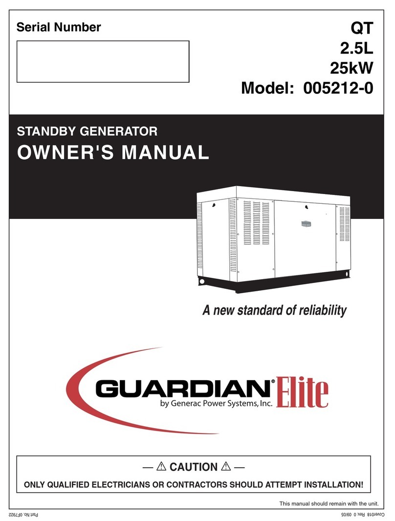
Owner’s Manual
ONLY QUALIFIED ELECTRICIANS OR CONTRACTORS
SHOULD ATTEMPT INSTALLATION!!
This manual should remain with the unit.
Liquid-cooled, Prepackaged
Standby Generators
Model Number: 004988-4
27kW NG, 30kW LP Vapor
2
INTRODUCTION
Thank you for purchasing this model of the standby
generator set.
Every effort was expended to make sure that the
information and instructions in this manual are both
accurate and current at the time the manual was writ-
ten. However, the manufacturer reserves the right to
change, alter or otherwise improve this product(s) at
any time without prior notice.
READ THIS MANUAL THOROUGHLY
If any portion of this manual is not understood, con-
tact the nearest Authorized Service Dealer for start-
ing, operating and servicing procedures.
Throughout this publication, and on tags and
decals affixed to the generator, DANGER, WARNING,
CAUTION and NOTE blocks are used to alert person-
nel to special instructions about a particular service
or operation that may be hazardous if performed
incorrectly or carelessly. Observe them carefully. Their
definitions are as follows:
DANGER
After this heading, read instructions that, if not
strictly complied with, will result in personal injury
or property damage.
After this heading, read instructions that, if not
strictly complied with, may result in personal injury
or property damage.
After this heading, read instructions that, if not
strictly complied with, could result in damage to
equipment and/or property.
NOTE:
After this heading, read explanatory statements
that require special emphasis.
These safety warnings cannot eliminate the hazards
that they indicate. Common sense and strict compli-
ance with the special instructions while performing the
service are essential to preventing accidents.
Four commonly used safety symbols accompany the
DANGER, WARNING and CAUTION blocks. The type
of information each indicates is as follows:
This symbol points out important safety informa-
tion that, if not followed, could endanger personal
safety and/or property of others.
This symbol points out potential explosion hazard.
This symbol points out potential fire hazard.
This symbol points out potential electrical shock
hazard.

The operator is responsible for proper and safe use
of the equipment. The manufacturer strongly recom-
mends that the operator read this Owner's Manual
and thoroughly understand all instructions before
using this equipment. The manufacturer also strong-
ly recommends instructing other users to properly
start and operate the unit. This prepares them if they
need to operate the equipment in an emergency.
OPERATION AND MAINTENANCE
It is the operator's responsibility to perform all safety
checks, to make sure that all maintenance for safe
operation is performed promptly, and to have the
equipment checked periodically by an Authorized
Service Dealer. Normal maintenance service and
replacement of parts are the responsibility of the
owner/operator and, as such, are not considered
defects in materials or workmanship within the terms
of the warranty. Individual operating habits and usage
contribute to the need for maintenance service.
Proper maintenance and care of the generator ensures
a minimum number of problems and keep operating
expenses at a minimum. See the Authorized Service
Dealer for service aids and accessories.
Operating instructions presented in this manual
assume that the standby electric system has been
installed by an Authorized Service Dealer or other
competent, qualified contractor. Installation of this
equipment is not a “do-it-yourself” project.
HOW TO OBTAIN SERVICE
When the generator requires servicing or repairs,
contact an Authorized Service Dealer for assistance.
Service technicians are factory-trained and are capa-
ble of handling all service needs.
When contacting an Authorized Service Dealer about
parts and service, always supply the complete model
number of the unit as given on the front cover of this
manual or on the DATA LABEL affixed to the unit.


AUTHORIZED SERVICE
DEALER LOCATION
To locate the nearest AUTHORIZED
SERVICE DEALER, please call this number:
1-800-333-1322
OR
Locate us on the web at:
www.generac.com

Table of Contents
Liquid-cooled 30 kW Generators
1
INTRODUCTION ............................................... IFC
SAFETY RULES ....................................................2
Section 1 — GENERAL INFORMATION............. 4
1.1 Generator..............................................................4
1.2 Transfer Switch.....................................................4
1.3 Automatic System Operation.................................4
1.4 Generator AC Connection Systems........................4
1.5 Main Circuit Breaker.............................................4
1.6 Generator Fuel System..........................................5
1.7 Engine Protective Devices......................................5
1.8 Unpacking .............................................................6
1.9 Lifting the Generator.............................................6
1.10 Specifications ........................................................7
1.11 Fuel Consumption .................................................7
1.12 Reconfiguring the Fuel System ..............................7
1.13 Torque Specifications ............................................8
1.14 Engine Oil Recommendations ...............................8
1.15 Coolant Recommendations....................................8
1.16 Before Installation .................................................8
Section 2 — INSTALLATION............................. 8
2.1 Standby Generator Installation .............................8
2.2 Generator Location ...............................................9
2.3 Generator Mounting and Support .........................9
2.4 Basic Standby Electric System..............................9
2.5 Emergency Circuit Isolation Method ...................10
2.6 Total Circuit Isolation Method.............................10
2.7 Grounding the Generator ....................................10
2.8 Generator AC Neutral Connections .....................10
2.9 Transfer Switch Start Signal Connections...........10
2.10 Battery Installation..............................................11
2.11 Preparation Before Start-Up................................11
Section 3 — OPERATION................................ 12
3.1 Using a Standard “GTS” Transfer Switch ...........12
3.2 Control Console Components..............................13
3.3 Manual Transfer and Startup..............................14
3.4 Engine Governor Adjustments ............................14
3.5 Retransfer and Shutdown ...................................14
3.6 Automatic Operation ...........................................14
3.7 Weekly Exercise Cycle .........................................15
Section 4 — MAINTENANCE........................... 15
4.1 Maintenance Performed by Authorized
Service Facilities..................................................15
4.2 Cooling System....................................................15
4.3 Overload Protection for Engine DC
Electrical System.................................................16
4.4 Checking Fluid Levels .........................................16
4.5 Maintenance Owner/Operator
Can Perform........................................................16
4.6 Miscellaneous Maintenance .................................18
4.7 Scheduled Maintenance.......................................20
Section 5 — TROUBLESHOOTING ................. 23
Section 6 — NOTES........................................ 24
Section 7 — INTALLATION DIAGRAM ............ 25
Section 8 — ELECTRICAL DATA .................... 26
Section 9 — EXPLODED VIEWS AND
PARTS LISTS ............................. 30
Section 10 — WARRANTY .................Back Cover
MOUNTING BASE
CONTACTOR
WIRE
HARNESS
7
5
6
16
ENGINE
FOOT
2
4
3
41
40
16
7
6
5
35
9
13
17
12
8
18
16
43
BLOCK
ENGINE
30
TO 44
35
34
39
36
33
44
42
22
20
32
38
18
31
20
21
TO
STARTER
STARTER
BOLT
TO
BLOCK
ENGINE
18
TO
11
1
12
10
14
REAR BEARING
13
15
37
14
CARRIER
3
4
16
2
30
Section 9 - Exploded Views and Parts
Liquid-cooled 30 kW Generators
Mounting Base — Drawing No. 0E6266-F
ITEM PART NO. QTY. DESCRIPTION
1 0E5822 1 BASEFRAME, WELDMENT 3.0L FORD
2 052860 4 NUT FLANGED HEX M12-1.75
3 052251 4 DAMPENER VIBRATION 40 BLUE
4 052257 4 SPACER .49 X .62 X 1.87 PWDR/ZNC
5 052252 4 DAMPENER VIBRATION
6 052259 4 WASHER FLAT M12
7 052891 4 SCREW HHC M12-1.75 X 80 G8.8
8 0536210213 1 ASSY GRNDWIRE 11"/3/8 & 5/16 LUG
9 074906 1 SCREW HHTT M6-1.0 X 20 BP
10 047411 1 SCREW HHC M6-1.0 X 16 BP
11 055414 1 LUG SLDLSS #2-#8 X 17/64 CU
12 026850 2 WASHER SHAKEPROOF EXT 1/4 STL
13 022097 1 WASHER LOCK M6-1/4
14 022473 2 WASHER FLAT M6-1/4 ZINC
15 049813 1 NUT HEX M6 -1.0 G8 YEL CHR
16 0A1694 4 1-1/2" BUTTON PLUG
17 052213 1 SCREW HHC M10-1.25 X 20 G8.8
18 025507 3 WASHER SHAKEPROOF EXT 7/16 STL
20 027482 2 WASHER SHAKEPROOF EXT 5/16 STL
21 022129 1 WASHER LOCK M8-5/16
22 045771 1 NUT HEX M8-1.25 G8 YEL CHR
23 * 051756 1 SCREW HHC M10-1.5 X 20 G8.8
24 * 046526 1 WASHER LOCK M10
25 * 022131 1 WASHER FLAT 3/8-M10 ZINC
26 * 055934M 1 CLAMP VINYL .75 X .343 Z
30 077483 REF. BATT 12VDC 75-AH 26
058665 REF. BATT 12VDC 90-AH 27F
31 038804D 1 CABLE BATT RED #4 X 20.00
32 038805AA 1 CABLE BATT BLK #4 X 30"
33 021991 1 EARTH STRAP
34 049814 1 SCREW HHC M10-1.5 X 25 G8.8
35 046526 2 WASHER LOCK M10
36 022131 1 WASHER FLAT 3/8 ZINC
37 075763 1 BOOT BATTERY CABLE
38 050331 1 BATTERY POST COVER BACLK -
39 050331A 1 BATTERY POST COVER RED +
40 0A4010 2 SCREW HHC M8-1.25 X 60 G8.8 FT
41 052858 2 NUT TOP LOCK FL M8-1.25
42 061902 1 HOLD DOWN BATTERY
43 059473 1 HOLD DOWN BATTERY
44 049820 2 NUT HEX LOCK M8-1.25 NY INS
* NOT SHOWN-USED TO HOLD DOWN I/N 32
Section 9 - Exploded Views and Parts
Liquid-cooled 30 kW Generators
Mounting Base — Drawing No. 0E6266-F
31
32
3
7
S
TATE
S
F
O
AM I
S
O
N FAR
S
IDE
S
TATE
S
F
O
AM I
S
O
N NEAR
S
IDE
17
L
AT
C
H DETAIL
30
3
1
3
4
38
2
3
2
3
4
27
43
18
40
4
7
"B
"
11
S
EE LAT
C
H
DETAIL
25
5
2
9
6
49
48
5
TO
"A"
T
YPI
C
AL
O
F R
OO
F PANEL THAT
R
E
Q
UIRE INSULATION.
S
E
CU
RE A
S
S
H
O
WN.
4
4
49
35
R
ADIAT
OR
SU
PP
O
R
T
33
25
47
7
4
49
4
36
4
18
4
26
44
4
4
4
8
4
2
9
"A"
"A"
"A""A"
12
13
53
17
5
2
48
"B
"
20
11
1
0
14
15
19
16
28
4
1
24
17
42
41
9
53
18
23
45
4
4
4
45
45
17
40
4
26
(
2-PLCS
)
TO
"B"
10
18
39
Section 9 - Exploded Views and Parts
Liquid-cooled 30 kW Generators
Enclosure — Drawing No. 0F1142-B
33
ITEM PART NO. QTY. DESCRIPTION
1 0E8411 1 INTAKE DUCT HSB
2 0E8042 1 DUCT DISCHARGE RH FRONT
3 0E8041 1 DUCT DISCHARGE LH FRONT
4 0C2454 62 SCREW TH-FRM M6-1 X 16 N WA Z/JS
5 0E8402 1 BAFFLE REAR BOTTOM
6 0E7808 1 POST CORNER LH REAR
7 0E7809 1 POST CORNER RH REAR
8 0E8387 1 BAFFLE REAR TOP
9 0E6986 2 DOOR COMPARTMENT SIDE
10 0F5552 1 SUPPORT R/H SIDE
11 089961 2 FOAM STRIP 3/4" WIDE X 3/16" THK (40" LG)
12 0A2115 4 WASHER NYLON .257
13 0E8404 1 BRACKET STIFFENER RH FRONT
14 0D2538A 1 HINGE LIFT OFF TYPE B KNUCKLE
15 0D2538 1 HINGE LIFT OFF TYPE B PIN
16 078115 8 WASHER SELF LOCKING DOME
17 022097 12 WASHER LOCK M6-1/4
18 022473 12 WASHER FLAT 1/4-M6 ZINC
19 0E7570 2 GASSPRING
20 0E7571 4 BALL STUD GASSPRING MOUNT
21 070015 4 NUT HEX 5/16-18 LOCK
22 0E7662 4 SCREW WING M6-1.00 X 25
23 0D2537A 1 HINGE LIFT OFF TYPE A KNUCKLE
24 0D2537 1 HINGE LIFT OFF TYPE A PIN
25 0D2023 3 GASKET CLIP-ON SELF GRIPPING (84" LG)
26 0E7869 2 BRACKET STIFFENING BACK
27 0E8001 1 MUFFLER BOX
28 0F5551 1 ROOF, W/SHOCK MOUNT
29 0E8406 1 BRACE FRONT TOP
30 0D3037A 1 LATCH 1/4 TURN NONLOCKING
31 0C7781 2 PAWL DOOR HSB
32 0E7794 1 SUPPORT LH SIDE
33 0E8052 1 MUFFLER BOX TOP
34 0D3037 1 LATCH QUARTER TURN LOCKING
35 0E8007 1 POST CORNER LH FRONT
36 0E8008 1 POST CORNER RH FRONT
37 0F1130 1 BRACE, FRONT BOT 3.0L FD STEEL
38 0E8055 1 DUCT DISCHARGE MID FRONT
39 026850 4 WASHER SHAKEPROOF EXT 1/4 STL
40 0912970063 2 ASSY WIRE 14AWG 7.5 #0 GRN/YEL
41 0912970064 2 ASSY WIRE 14AWG 7.5 #0 GRN/YEL
42 049813 2 NUT HEX M6 X 1.0 G8 YEL CHR
43 0E8665 1 BRACKET STIFFENER LH FRONT
44 0E7829U 2 AI BRACE PANEL
45 0E7829N 2 AI ROOF PANEL 2
46 0E7829T 1 AI SUPPORT RH PANEL
47 0E7829S1 AI SUPPORT LH PANEL
48 0E7829R 2 AI CORNER POST PANEL 2
49 0E7829P 4 AI CORNER POST PANEL 1
50 * 0E8441 1 KIT INSULATION 3.0L HSB
51 0E7829A 1 AI ROOF PANEL 1
52 0E7829B 2 AI DOOR PANEL
53 043116 8 SCREW HHC M6-1.0 X 12 G8.8
* ALL ITEMSNOTATED WITH "AI" ARE COMPONENTSOF 0E8441
Section 9 - Exploded Views and Parts
Liquid-cooled 30 kW Generators
Enclosure — Drawing No. 0F1142-B
34
Section 9 - Exploded Views and Parts
Liquid-cooled 30 kW Generators
Control Panel — Drawing No. 0E7118-K
35
ITEM PART NO. QTY. DESCRIPTION
1 0E7195 1 CONTROL BOX HSB
2 0E7196 1 COVER FRONT PANEL HSB
3 0E7197 1 COVER TOP PANEL HSB
4 0E7193 1 DECAL WARNINGSHSB
5 0E7194 1 DECAL CONTROLSHSB
6 0E4494 1 SWITCH ROC DPDT ON-OFF-ON
7 082573 1 SWITCH ROCKER DPST 125V SPD
8 032300 2 HOLDER FUSE
9 022676 1 FUSE 15A X AGC15
10 067682B 1 FUSE 4A SLO BLO GLASS
11 060015 1 FITTING CONDUIT 90D 3/8"
12 054199 1 DECAL DANGER HIGH VOLTAGE
13 0C2657 1 TRANSFRMR 16V 6VA
14 099076 1 TRANSFORMER 16V 56VA
15 040213 2 PCB SUPPORT SNAP-IN 1/4"
16 0E9668 1 ASSY PCB HSB CONTROLLER
17 067680 1 ASSY VOLTAGE REGULATOR 60HZ
18 0E6875A 1 RELAY 12VDC C FORM W/DIODE
19 0E6881 * REF. SOCKET RELAY
20 0C5139 * REF. CONN DEUTSCH RECEPT GY/FLN
21 0C5142 * REF. CONN DEUTSCH RECEPT WDGE
BLKHD
22 0E3161 1 ASSY BOSCH GOV DRIVER
23 054450 1 CIRCT BRK 5.5 X 1 ETA 46-500-P
24 0D5070A 1 ASSY 2A 12V UL BATTERY
CHARGER
25 0E2514 1 FITTING CONDUIT STR 1-1/2"
26 0A9457 1 DECAL NEUTRAL
27 0E7539 1 DECALCUSTOMER CNNCTN XFER
SW
28 046357 * REF. BLOCK TERM 20A 6 X 6 X 1100V
29 0D3719B 1 DECAL CUSTOMER CNNCTN
30 057073 1 JUNCTION BLOCK 3/8-16
31 0E7283 1 CB 0150A2P240V SQN2 LL
0E3628 1 CB 0200A2P240V SQN2 LL
32 0E3664 1 BASE QN CIRCUIT BREAKER
33 0E7539A 1 DECAL TB1 HSB CONTROL PANEL
34 0D4698 * REF. BLOCK TERM 20A 6 X 3 X 1100V
35 0E7252 1 BRACKET CB 221.5 X 10²
36 0C1229 1 DECAL WARNING ELECTRICAL
SHOCK
ITEM PART NO. QTY. DESCRIPTION
37 0C1127 1 DECAL AVR COVER
38 0A1441B 1 COVER PLATE, AVR
39 0E7128 1 HARNESS CNTRL PNL (NOT
SHOWN)
40 0E7358 8 SCREW PPPH HI-LO #4-24 X 3/8
41 074908 6 SCREW HHTT M5-0.8 X 10 BP
42 0C5141 1 CONN DEUTSCH GASKET 8/12 POS
DT
43 0C2699 11 SCREW PHTT #6-32 X 3/8 ZYC
44 0C2323 4 SCREW PHTT #6-32 X 5/8 ZYC
45 022155 15 WASHER LOCK #6
46 0C2265 4 SCREW PHTT M4-0.7 X 12 ZYC
47 022264 4 WASHER LOCK #8-M4
49 020911 2 SCREW PPHM M5-0.8 X 30 ZINC
50 066849 2 SCREW HHTT M5-0.8 X 16
51 022152 4 WASHER LOCK #10
52 023897 3 WASHER FLAT #10 ZINC
53 051716 2 NUT HEX M5-0.8 G8 YEL CHR
54 090388 2 SCREW HHTT M6-1.0 X 12 ZINC
55 042568 4 SCREW HHC M6-1.0 X 20 G8.8
56 022097 8 WASHER LOCK M6-1/4
57 022473 6 WASHER FLAT 1/4-M6 ZINC
58 0441140187 2 WIRE ASSY 3" X (2) 3/16" TABS
59 070370 2 WASHER MICA .203
60 023762 1 WASHER SHAKEPROOF EXT #10
STL
61 055444 1 HEATSINK
62 030468 1 WASHER STEP NYLON .20
63 049939 1 RECTIFIER MSC 12A 600V 1N1206R
64 022158 1 NUT HEX #10-32 STEEL
65 022985 1 WASHER FLAT #6 ZINC
66 038750 2 SCREW HHC M6-1.0 X 30 G8.8
67 0A2115 4 WASHER NYLON .257
68 0C2454 4 SCREW THF M6-1 X 16 N WA Z/JS
69 0F6146 1 HANG TAG 2 WIRE START (NOT
SHOWN)
* ITEMSINCLUDED ASPART OF I/N 39
Section 9 - Exploded Views and Parts
Liquid-cooled 30 kW Generators
Control Panel — Drawing No. 0E7118-K
11
65
17
57
24
61
60
30
25
58
35
39
36
WIRE
GROUND
39
32
31
35
79
24
50
54
53
43
2
42
38
61
53
51 14
55
60
25
85
57
58
87
69
36
& REPLACE
REMOVE
35
39
86
68
66
67
32
16 18
19
80
48
47
42
41
44
45
31
30
81
88
84
42
78
49
21
49
46
20
47
47
46
4
43
64
38
42
63
1
26
42
15
47
43
81
238 42
28
34
REAR UPPER
BAFFLE
40
42
36
5
6
7
35 37
89
36
43
3
8
35
83
12
29
74
72
73
38
10
82
33
36
42
84
34
35
27
Section 9 - Exploded Views and Parts
Liquid-cooled 30 kW Generators
Engine — Drawing No. 0F6836-B
36
ITEM PART NO. QTY. DESCRIPTION
1 0E6201 1 ENGINE 3.0L FORD (FD) (MAKE)
2 0E8824 2 STAMPING ENG FOOT 3.0L FORD
3 0E8963 1 PULLEY CRANKSHAFT 3.0L FORD
RD
4 0E9020 1 BRACKET DC ALT 3.0L FORD
5 0A1232 1 D.C. ALTERNATOR ASSY
6 0A7801B 1 PULLEY POLY-V 82 OD.
7 0A5610 1 BRACKET ALTERNATOR
8 0E6308 1 PULLEY WATERPUMP 3.0L FORD
(RD)
9 ** 0E7804 1 HARN IGNITION 3.0L FORD (NOT
SHOWN)
10 0D3488F 1 BELT SERPENTINE 38.35
11 0E7996 1 CLUTCH COOLING FAN FORD
12 0E8006 1 FAN 18" 7 BLADE STEEL ECS
14 0A6751 1 SWITCH HI-TEMP 245D X 3/8NPT
15 0E0561 1 ASSY WATER LEVEL SENSOR C/E
PL
077043H 1 CONDUIT FLEX .25"ID (6"LG) (NOT
SHOWN)
16 0E6729 1 STARTER DELCO-REMY 12V
17 0E6703 1 COVER FLYWHEEL ACCESS 3.0L
HSB
18 0E6667 1 ENGINE ADAPTER 3L FORD
19 0E5048 1 FLEXPLATE 3.0L FORD
20 035579 1 BUSHING REDUCER 1/4 TO 1/8
21 0A8584 1 SWITCH OIL PRESSURE 10PSI
2POL
24 083896 6 WASHER LOCK 1/4-M6 SS
25 084929 6 WASHER FLAT 1/4 SS
26 055597 1 SCREW HHC M12-1.75 X 85 G8.8
27 0F6151 1 CAP RUBBER
28 057823 1 CLAMP HOSE #10 .56-1.06
29 056739 1 RELAY SOLENOID 12VDC PNL MNT
30 047411 6 SCREW HHC M6-1.0 X 16 G8.8
31 022097 6 WASHER LOCK M6-1/4
32 022473 6 WASHER FLAT 1/4-M6 ZINC
33 047411 4 SCREW HHC M6-1.0 X 16 G8.8
34 040976 8 SCREW SHC M8-1.25 X 20 G12.9
35 022129 28 WASHER LOCK M8-5/16
36 022145 22 WASHER FLAT 5/16-M8 ZINC
37 045771 1 NUT HEX M8-1.25 G8 YEL CHR
38 049814 6 SCREW HHC M10-1.5 X 25 G8.8
39 049821 16 SCREW SHC M8-1.25 X 30 G12.9
40 059980 4 SCREW HHC M10-1.5 X 25 G10.9
41 0D5417 REF. SCREW HHC M10-1.0 X 25 G10.9
42 046526 18 WASHER LOCK M10
43 022131 11 WASHER FLAT 3/8-M10 ZINC
44 059982 4 SCREW SHC M12-1.75 X 45 G10.9
45 098780 2 SCREW HHC M12-1.75 X 65 G8.8
46 051769 3 WASHER LOCK M12
ITEM PART NO. QTY. DESCRIPTION
47 049808 4 WASHER FLAT M12
48 051430 4 WASHER SHAKEPROOF INT 1/2
49 045773 3 NUT HEX M12-1.75 G8 YEL CHR
50 0E6203C 1 COIL IGNITION 3.0L FORD
51 0E6679 2 BRACKET IGN COIL 3.0L FORD
53 049226 7 WASHER LOCK M5
54 091526 3 SCREW PPHM M5-0.8 X 12 ZNC
55 093278 4 SCREW HHTT M5-0.8 X 25 BP
56 0F7000 1 HARN ENGINE 3.0L FORD HSB CAR
(NOT SHOWN)
57 0E7163 2 GASKET EXHAUST 3.0L FORD
58 0E5527 2 MANIFOLD EXHAUST 3.0L FORD
60 0E7202 2 HEAT SHIELD 260 X 80 HOT
61 085296 6 SCREW HHC 1/4-20 X 1/2 SS
62 0E6203D 1 WIRE SET 3.0L FORD (NOT
SHOWN)
63 057772 1 WASHER NYLON .565
64 057765 1 ADAPTER M14-1.50 X 3/8 NPT
65 055596 1 BARBED STR 3/8NPT X 3/8
66 069860C 1 HOSE OIL DRAIN ASSY 21"
67 057822 2 CLAMP HOSE #8 .53-1.00
68 069811 1 CAP HEX 1/4 NPT BRASS
69 061012 1 PLUG STD PIPE 1/8 SOCKET HEAD
70 * 065852 1 SPRING CLIP HOLDER .37-.62
71 * 0A2111 1 SCREW SWAGE 10-32 X 5/16 Z/YC
72 057073 1 JUNCTION BLOCK 3/8-16
73 066849 2 SCREW HHTT M5-0.8 X 16
74 022152 2 WASHER LOCK #10
75 0E7880 2 CLIP SPARK PLUG 3P
SCREWMOUNT (NOT SHOWN)
76 0E7880A 4 CLIP SPARK PLUG 2P
SCREWMOUNT (NOT SHOWN)
77 0E7880B 1 CLIP SPARK PLUG 3P FREEHANG
(NOT SHOWN)
78 055934C 1 CLAMP VINYL .5 X .406 Z
79 027482 1 WASHER SHAKEPROOF EXT 5/16
STL
80 0E8940 1 SPACER FLEXPLATE HSB
81 0A7387 2 SCREW HHC M10-1.5 X 40 G10.9
82 022097 4 WASHER LOCK M6-1/4
83 022473 4 WASHER FLAT 1/4-M6 ZINC
84 055934H 2 CLAMP VINYL .62 X .406 Z
85 0F5966 1 REFLECTIVE HEAT SHIELD 3.0L FD
86 022985 3 WASHER FLAT #6 ZINC
87 036261 3 RIVET POP .125 X .275 SS
88 0F6658 1 COVER EGR
89 0F6809 1 ADAPTER, WATER PUMP
* NOT SHOWN-USED TO HOLD OIL DRAIN ASSEMBLY.
** NOT SHOWN
Section 9 - Exploded Views and Parts
Liquid-cooled 30 kW Generators
Engine — Drawing No. 0F6836-B
37
38
27
FRAME
11
10
9
12
3
8
9
26
25
"A"
20
21
TO WATER
12
4
PUMP
6
15
17
713
1
15
35
24
22
23
2
24
12
31
28
32
12
TO "A"
18
14
HOUSING
THERMOSTAT
TO
29
12
33
35
30
ENGINE
12
TO
Section 9 - Exploded Views and Parts
Liquid-cooled 30 kW Generators
Radiator — Drawing No. 0F6848-B
39
ITEM PART NO. QTY. DESCRIPTION
1 0E9947 1 RADIATOR R-IN,L-OUT 658X489X49
2 0E6340 1 VENTURI 3.0L FORD HSB
3 0E8531 2 SIDE SUPPORT RADIATOR HSB
4 0E6398 1 TUBE LOWER RAD 3.0L FORD HSB
5 0F6630 1 HOSE RADIATOR UPPER
6 080713 1 BRACKET COOLANT TANK
7 076749 1 TANK COOLANT RECOVERY
8 049814 4 SCREW HHC M10-1.5 X 25 G8.8
9 022131 8 WASHER FLAT 3/8-M10 ZINC
10 046526 4 WASHER LOCK M10
11 045772 4 NUT HEX M10-1.5 G8 YEL CHR
12 035685 6 CLAMP HOSE #28 1.32-2.25
13 0E8562 1 FAN GUARD HSB
14 058443 4 SCREW CRIMPTITE 1/4-20 X 5/8
15 0C2454 9 SCREW TH-FRM M6-1 X 16 N WA Z/JS
17 048031C 1 CLAMP HOSE BAND 1/4
18 029032 1 HOSE 9/32 ID (30" LG)
20 046627 1 CAP RADIATOR
21 069811 1 CAP HEX 1/4 NPT BRASS
22 065852 1 SPRING CLIP HOLDER .37-.62
23 0A2111 1 SCREW SWAGE 10-32 X 5/16 Z/YC
24 052250 2 TAPE FOAM 1 X 1 (27" LG)
25 035461 1 BARBED STR 1/4 NPT X 3/8
26 0C7649 1 CLAMP HOSE .38-.87
27 069860C 1 HOSE OIL DRAIN ASSY 21"
28 0F6746 1 TUBE UPPER COOLANT C4 3.0L
29 0F6631 1 HOSE RADIATOR ENGINE
30 0F6657 2 SUPPORT TUBE RADIATOR
31 055934N 2 CLAMP VINYL 1.31 X .281 Z
32 092079 2 SCREW HHTT M6-1.0 X 25 BP
33 022097 2 WASHER LOCK M6-1/4
35 047411 2 SCREW HHC M6-1.0 X 16 G8.8
Section 9 - Exploded Views and Parts
Liquid-cooled 30 kW Generators
Radiator — Drawing No. 0F6848-B
40
28
"B"
31
10
16
4
2
17
5
9
1
7
6
29
32
30
11
29
13
15
8
3
12
6
13
AIR
TO
CLEANER
34
33
29
14
TO "B"
19
26
27
18
43
41
40
21
28
20
26
25
42
39
Section 9 - Exploded Views and Parts
Liquid-cooled 30 kW Generators
Fuel System — Drawing No. 0F6849-A
41
ITEM PART NO. QTY. DESCRIPTION
1 * --------- 1 WELDMENT MOUNTING BASE
2 075580 1 FLANGE FUEL INLET
3 0E7691 1 ASSY REGULATOR 3.0L NG OR LPV
4 039253 2 SCREW HHC M8-1.25 X 20 G8.8
5 022145 2 WASHER FLAT 5/16 ZINC
6 022129 4 WASHER LOCK M8-5/16
7 045771 2 NUT HEX M8-1.25 G8 YEL CHR
8 042907 2 SCREW HHC M8-1.25 X 16 G8.8
9 0C2454 2 SCREW TH-FRM M6-1 X 16 N WA Z/JS
10 026307 1 ELBOW 90D STREET 3/4
11 0E1056 1 FUEL HOSE ASSY NAT.GAS/L.P.V.
12 0E6584 1 BRACKET REGULATOR 3.0L FORD HSB
13 057823 2 CLAMP HOSE #10 .56 - 1.06
14 059194 1 HOSE 5/8 ID LPG & NG (20" LG)
15 044117 1 BARBED STR 3/8 NPT X 5/8
16 0D1509 1 DECAL INLET PRESSURE
17 050279 1 DECAL FUEL INLET NG
18 0E6123 1 INTAKE ADAPTER 3.0L FORD-BOSCH
19 0E6586 1 GASKET BOSCH 32
20 0E4395 1 ACTUATOR BOSCH 32 GOVERNOR
21 057753B 1 HOSE 1.5 ID X 2 LG 20R4
25 047487 4 SCREW SHC M6-1.0 X 18 G12.9
26 022097 8 WASHER LOCK M6-1/4
27 051751 4 SCREW HHC M6-1.0 X 50 G8.8
28 035685 2 CLAMP HOSE #28 1.32-2.25
29 0C7649 4 CLAMP HOSE .38-.87
30 047290 1 HOSE 3/8 ID SINGLE BRAID (305mm [22"] LONG)
31 047290 1 HOSE 3/8 ID SINGLE BRAID (432mm [13"] LONG)
32 0A4121 1 VALVE PCV
33 0E6609 1 GROMMET ROCKER COVER 3.0LFORD
34 049099 1 BARBED EL 90 3/8 X 3/8 PLST
35 ** 055934M 1 CLAMP VINYL .75 X .343 Z
36 ** 047411 1 SCREW HHC M6-1.0 X 16 G8.8
37 ** 022097 1 WASHER LOCK M6-1/4
38 ** O22473 1 WASHER FLAT 1/4-M6 ZINC
39 0E9295A 1 ASSY THROTTLE 27MM
40 0E6382A 1 VENTURI HOLDER W/32MM ACTUATOR
41 0E7121 1 O-RING 47.625 ID X 2.38 WIDTH
42 0E6376A 1 VENTURI, 27 ID THROTTLE W/CHOK
43 0F2119 1 O-RING 45.63 ID X 2.62 WIDTH
* SHOWN IN OTHER VIEW
** NOT SHOWN-USED TO HOLD #31 IN PLACE
Section 9 - Exploded Views and Parts
Liquid-cooled 30 kW Generators
Fuel System — Drawing No. 0F6849-A
42
3
LOCKTIGHT
LOCKTIGHT
7
15
17
8
7
6
18
4
16
LEADS
5
2
9
13
21
19
20
14
10
11
12
30
1
31
Section 9 - Exploded Views and Parts
Liquid-cooled 30 kW Generators
Alternator — Drawing No. 0F5092-B
43
ITEM PART NO. QTY. DESCRIPTION
1 0F1659A 1 ROTOR 390 15KW 1P DIRECT HSB (2.5L FORD)
0F1657A 1 ROTOR 390 20KW 1P DIRECT HSB (2.5L FORD)
0F1655A 1 ROTOR 390 25KW 1P DIRECT HSB (2.5L FORD)
0F5073A 1 ROTOR 390__30AD1 HSB TECUM
0E7413A 1 RTR 390 40KW 1P DIRECT HSB
2 0F1660A 1 STR 390 15AD HSB (382MM LONG) (2.5L FORD)
0F1658A 1 STR 390 20AD HSB (382MM LONG) (2.5L FORD)
0F1656A 1 STR 390 25AD HSB (382MM LONG) (2.5L FORD)
0F5074A 1 STR-390__30AD1 HSB TECUM
0E7412A 1 STR-390--40AD HSB (433MM LONG)
3 0E5706 1 REAR BEARING CARRIER 390/DRCT
4 0E5048 REF FLEXPLATE 3.0L FORD
0E5048B REF FLEXPLATE 2.5L FORD
0E5048A REF FLEXPLATE HSB 3.9L CHRYSLER
5 0E6668 1 FLYWHEEL ASSY 3.0L HSB LG GEAR
6 0E6076 1 REVCOR FAN 10.75 X 2 W/PRESS DIS
7 046526 8 WASHER LOCK M10
8 051755 4 SCREW HHC M10-1.5 X 16 G8.8
9 04576100BK 4 STUD M14-2.0 X 490 G5 ZINC (3.0L FORD & 2.5L FORD)
04576100BF 4 STUD M14-2.0 X 540 G5 ZINC
10 043123 4 WASHER LOCK M14
11 051779 4 NUT HEX M14-2.0 G8 YEL CHR
12 0E7587 1 ASSY BRUSH HOLDER 390/HSB
13 023365 1 WASHER SHAKEPROOF INT #8
14 092980 4 SCREW PPHM M4-0.7 X 25
15 057192 4 SCREW SHC M10-1.5 X 30 G12.9
16 0A2602 1 WASHER FLAT .688 ID X 3.25 OD
17 042558 1 KEY SQ 3/8 X 1 STEEL
18 0A2601 1 SCREW HHC M16-2.0 X 45 G8.8
19 022264 4 WASHER LOCK #8-M4
20 038150 4 WASHER FLAT #8 ZINC
21 077043F 1 CONDUIT FLEX 1-1/4" (30" LG - 3.0L FORD & 3.9L CHRYSLER)
077043F 1 CONDUIT FLEX 1-1/4" (18" LG - 2.5L FORD)
ROTOR REPLACEMENT PARTS
30 047248 1 BALL BEARING-45 MM
31 070892 1 SLIP RING -MACHINED-
Section 9 - Exploded Views and Parts
Liquid-cooled 30 kW Generators
Alternator — Drawing No. 0F5092-B
ITEM PART NO. QTY. DESCRIPTION
1 0F0738 1 MUFFLER 7"X9"-(2)2"IN/2.5"OUT
2 0F6258 1 PIPE MUFFLER OUT
3 044149 2 GASKET EXHAUST RING
4 0F1008 1 EXHAUST PIPE LH 3.0L HSB
5 0F1009 1 EXHAUST PIPE RH 3.0L HSB
6 039288 1 SCREW HHC M8-1.25 X 55 G8.8
7 0E5914 1 BRACKET MUFFLER 3.0L FORD
HSB
8 0E8726 2 STRAP MUFFLER
9 0E0170 2 EXHAUST BLANKET 750MM
10 036797 2 BOLT U 5/16-18 X 2.25
11 080762 1 BOLT U 3/8-16 X 2.62
ITEM PART NO. QTY. DESCRIPTION
12 0E8816 2 EXHAUST FLANGE 2" PIPE
13 085917 8 WASHER LOCK 3/8 SS
14 0D2611 4 SCREW HHC 3/8-16 X 1-3/4 SS
15 039253 2 SCREW HHC M8-1.25 X 20 G8.8
16 022145 4 WASHER FLAT 5/16-M8 ZINC
17 022129 7 WASHER LOCK M8-5/16
18 045771 3 NUT HEX M8-1.25 G8 YEL CHR
19 0C2454 4 SCREW TH-FRM M6-1 X 16 N WA
Z/JS
20 022259 4 NUT HEX 5/16-18 STEEL
21 022241 2 NUT HEX 3/8-16 STEEL
44
M
ANIF
O
L
D
1
0
1
6
1
5
6
2
0
8
1
6
1
0
17
2
1
MANIF
O
L
D
4
3
12
9
CO
MPARTMEN
T
1
8
1
9
2
0
17
T
O
1
3
11
17
8
1
6
21
T
O
1
6
5
17
1
8
7
1
9
3
T
O
14
1
3
12
9
Section 9 - Exploded Views and Parts
Liquid-cooled 30 kW Generators
Exhaust — Drawing No. 0F0968-B
45
ITEM PART NO. QTY. DESCRIPTION
1 0E5193 1 PLATE AIR CLEANER ADAPTER
2 0E0519A 1 ADAPTER CARBURETOR W/PVC CONN
3 049226 4 WASHER LOCK M5
4 049815 4 SCREW HHC M5-0.8 X 16 G8.8
5 0C8127 1 ELEMENT AIR CLEANER
6 022127 1 NUT HEX 1/4-20 STEEL
7 062974 1 STUD TH 1/4-20 X 4-1/2 G2 ZNC
8 0A5547 1 COVER - AIR CLEANER
9 037561 1 NUT WING 1/4-20 NYLK
4
7
1
6
2
5
3
9
8
Section 9 - Exploded Views and Parts
Liquid-cooled 30 kW Generators
Air Cleaner — Drawing No. 0F6850-A

Other Guardian Inverter manuals

Guardian 004700-0 Installation instructions

Guardian

Guardian 004700-0 Installation instructions

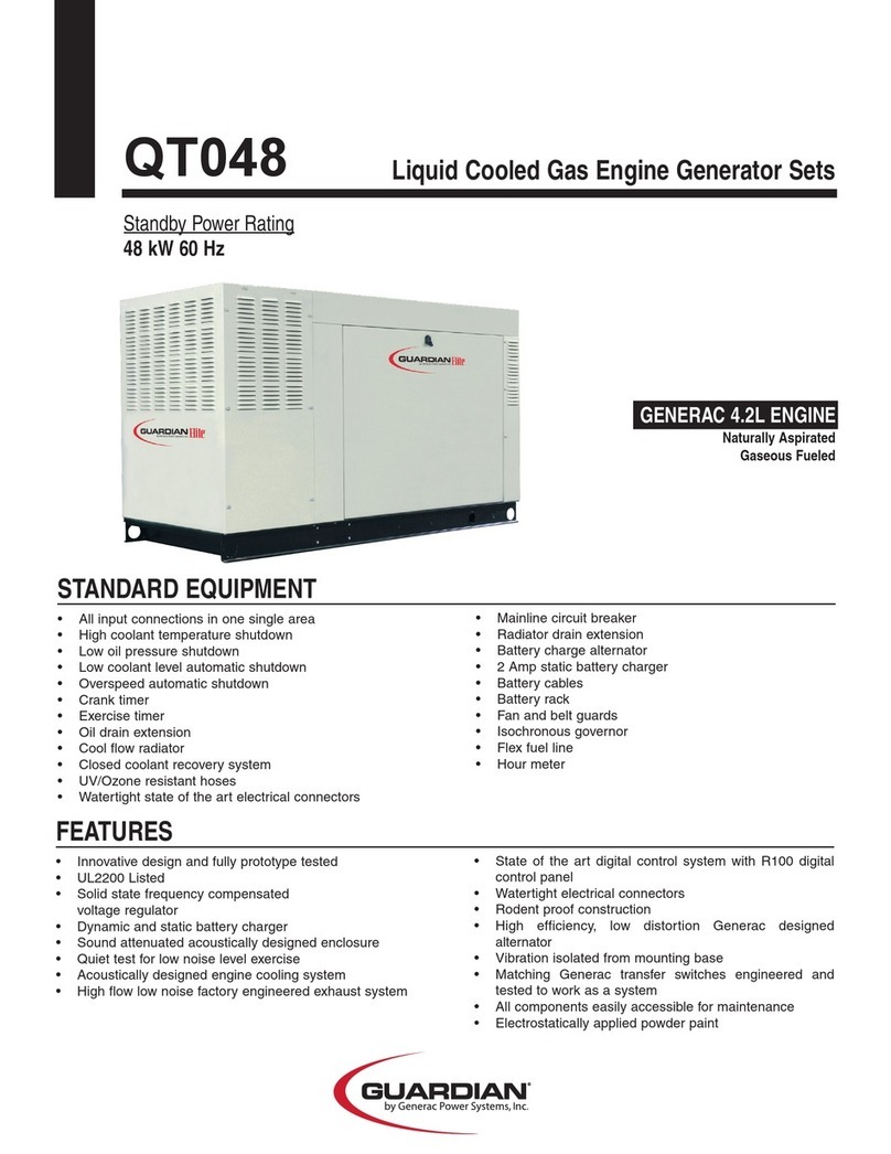
Guardian QT048 User manual

Guardian

Guardian QT048 User manual

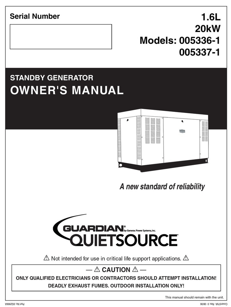
Guardian QuietSource 005336-1 User manual

Guardian

Guardian QuietSource 005336-1 User manual

Guardian 4389 Operating instructions

Guardian

Guardian 4389 Operating instructions

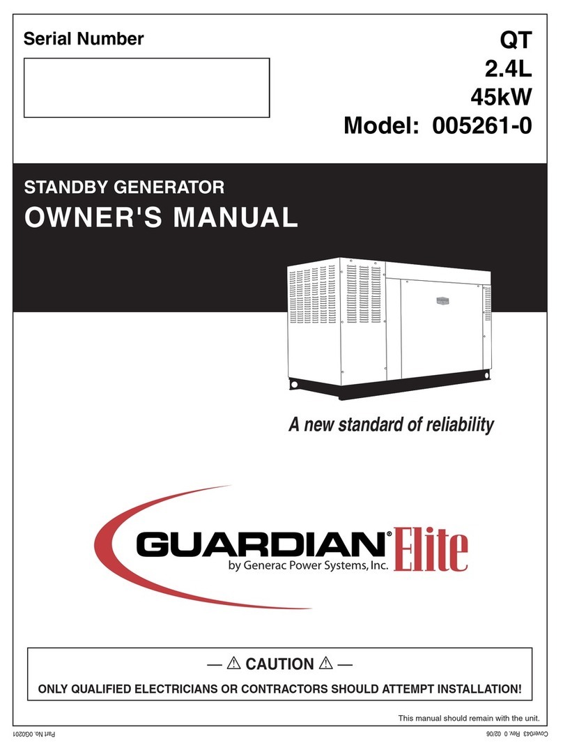
Guardian 005261-0 User manual

Guardian

Guardian 005261-0 User manual

Guardian 4700 Operating instructions

Guardian

Guardian 4700 Operating instructions

Guardian 005212-0 User manual

Guardian

Guardian 005212-0 User manual

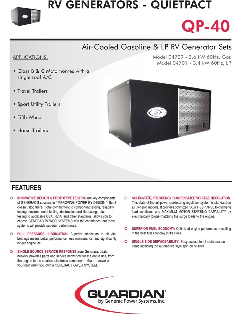
Guardian QP-40 User manual

Guardian

Guardian QP-40 User manual

Guardian QUIETPACT 85D Operating instructions

Guardian

Guardian QUIETPACT 85D Operating instructions

Guardian 4270 Operating instructions

Guardian

Guardian 4270 Operating instructions

Guardian QT060 User manual

Guardian

Guardian QT060 User manual

Guardian QT027 User manual

Guardian

Guardian QT027 User manual

Guardian 04389-3 Installation instructions

Guardian

Guardian 04389-3 Installation instructions

Popular Inverter manuals by other brands

HP 33120A installation instructions

HP

HP 33120A installation instructions

Trannergy TRM025KTL user manual

Trannergy

Trannergy TRM025KTL user manual

EPC Inverta Series user manual

EPC

EPC Inverta Series user manual

SMA 3000TL-US installation manual

SMA

SMA 3000TL-US installation manual

Heinner VGEN002 instructions

Heinner

Heinner VGEN002 instructions

2hp Brst manual

2hp

2hp Brst manual

SOLIS Solis-75K-5G Installation and operation manual

SOLIS

SOLIS Solis-75K-5G Installation and operation manual

Power Science CF-1500-12 Series user manual

Power Science

Power Science CF-1500-12 Series user manual

Good Will Instrument GFG-3015 Operation manual

Good Will Instrument

Good Will Instrument GFG-3015 Operation manual

IOTA IIS-35-HE instruction manual

IOTA

IOTA IIS-35-HE instruction manual

CE+T Power Bravo 10 - 48/230 user manual

CE+T Power

CE+T Power Bravo 10 - 48/230 user manual

Gardigo 70015 instruction manual

Gardigo

Gardigo 70015 instruction manual

Goodwe GW009K-DT user manual

Goodwe

Goodwe GW009K-DT user manual

Yamaha EF2000iS - Inverter Generator owner's manual

Yamaha

Yamaha EF2000iS - Inverter Generator owner's manual

Anern 3.2KW user manual

Anern

Anern 3.2KW user manual

Toshiba TOSVERT VF-AS1 Series instruction manual

Toshiba

Toshiba TOSVERT VF-AS1 Series instruction manual

SolarVu AE 500NX installation guide

SolarVu

SolarVu AE 500NX installation guide

Kostal PLENTICORE BI Short manual

Kostal

Kostal PLENTICORE BI Short manual

manuals.online logo
manuals.online logoBrands
  • About & Mission
  • Contact us
  • Privacy Policy
  • Terms and Conditions

Copyright 2025 Manuals.Online. All Rights Reserved.