- 2 - tousek / E_TX-310_03 / 21. 03. 2019
GENERAL WARNING AND SAFETY NOTES for installation
• These installation and operating instructions form an integral part of the product TX310 and they have been
specically written for professional installers trained and skilled in the trade and should be carefully read in
their full length before carrying out the installation. This is for Radio transmission system TX 310, and not
for the complete installaion of automatic gate. After the installation this manual has to be handed over to the
user.
• Installation, connection, adjustments, putting into operation, and servicing may only be carried out by trained
professionals in full accordance with these installation- and operating instructions.
• Before carrying out works at the gate-system, the power supply has to be turned o.
• The arrangement of the components is dependent on the structural conditions and the gate design.
• The switching device may only be used to hedge dangers at crushing and shearing points on automatic sliding
gates (specications regular use). Any other use is prohibited.
• When using non-original components (including safety edges) any warranty or liability expires.
• The national and international regulations for gate safety must be observed. The safety function of the applica-
tion must always be considered as a whole and never referred only to the individual plant part.
• Connections must be observed and complied with in accordance with the applicable EC or national standards
in their current version.
• The current in the specic case OVE / VDE regulations and standards must be observed.
• The EU Machine Directive, laws and rules concerning the prevention of accidents, and laws and standards which are in
force in the EU and in the individual countries have to be strictly followed.
• The packaging materials (cardboard, plastic, EPS foam parts and lling material etc.) have to be properly disposed of
in accordance with the applying recycling- and environmental procection laws. They may be hazardous to children and
therefore have to be stored out of children´s reach.
• The product is not suitable for installation in explosion-hazardous areas.
• The product may only be used in accordance with its original purpose, for which it has been exclusively designed, and
which is described in these installation and operating instructions. The TOUSEK Ges.m.b.H. rejects any liability if the
product is used in any way not fully conforming to its original purpose as stated herein.
• Children have to be instructed, that the gate facility as well as the belonging parts may not be used improperly, e.g. for
playing. Furthermore handheld transmitters have to be kept in safe places and other impulse emitters as buttons and
switches have to be installed out of children‘s reach.
• The TOUSEK Ges.m.b.H. rejects any liability for claims resulting from usage of the product in combination with compo-
nents or devices which do not fully conform to the applying safety laws and rulesvorschriften entsprechen.
• Only original spare- and replacement parts may be used for repair of the product.
Declaration of Conformity:
The company TOUSEK Ges.mbH, Zetschegasse 1, 1230 Vienna, declares that the radio transmission system TX 310
following directives:
- Machinery Directive 2006/42 / EC, the R & TTE Directive 1999/5 / EC
It was here applied the following standards: EN ISO 13849-1, EN 12978
October 2013
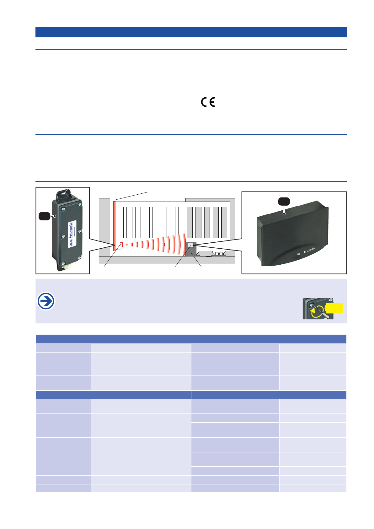
Important
The radio transmission system TX 310 is only suitable for use with tousek products!
This manual is the sole property of the TOUSEK Ges.m.b.H. and may not be made available to competitors. All rights reserved. No part of it may be reproduced without our prior
written permission. We will not accept liability for any claims resulting from misprints or errors. This edition of the manual replaces all earlier publications of the same.