manuals.online logo
Brands
  1. Home
  2. •
  3. Brands
  4. •
  5. Vertex Standard
  6. •
  7. Transceiver
  8. •
  9. Vertex Standard Pilot VXA-210 User manual

Vertex Standard Pilot VXA-210 User manual

©2002 VERTEX STANDARD CO., LTD. Printed in Japan.
EC016N95A
Service Manual
Air Band Transceiver
Operating Manual Reprint ...................................2
Specifications ..........................................................6
Installation of the SU-1..........................................7
CE41 Programming Software ...............................8
Exploded View & Miscellaneous Parts ..............9
Block Diagram.......................................................10
Circuit Description ...............................................11
Alignment ............................................................. 13
Board Unit (Schematics, Layouts & Parts) ...... 17
Main Unit ......................................................... 17
Contact Unit..................................................... 31
VR Unit............................................................. 32
SW Unit ............................................................ 33
The Vertex Standard VXA-210 Pilot is a compact, stylish, solid hand-held transceiver providing communication (transmit
and receive) capability on the International Aircraft Communication Band (“COM” band: 118 ~ 136.975 MHz), and it addi-
tionally provides VOR and CDI navigation features on the “NAV” band (108 ~ 117.975 MHz).
The VXA-210 includes Temperature display with our exclusive Omni-GlowTM display back-light for minimal degrada-
tion of your night vision, NOAA weather band monitoring, 8-character Alpha/Numeric Display, 50 Memory Channels, and
100 “Book Memory” Channels. And the optional Barometric Pressure Unit (SU-1) provides readout of barometric pressure,
altitude, and density altitude.
The following pages describe the Controls & Connectors, Accessories & Options, and Specification of the VXA-210.
With proper care and operation, the transceiver will provide many years of reliable communications.
VXA-210
VERTEX STANDARD CO., LTD.
4-8-8 Nakameguro, Meguro-Ku, Tokyo 153-8644, Japan
VERTEX STANDARD
US Headquarters
17210 Edwards Rd., Cerritos, CA 90703, U.S.A.
International Division
8350 N.W. 52nd Terrace, Suite 201, Miami, FL 33166, U
YAESU EUROPE B.V.
P.O. Box 75525, 1118 ZN Schiphol, The Netherlands
YAESU UK LTD.
Unit 12, Sun Valley Business Park, Winnall Close
Winchester, Hampshire, SO23 0LB, U.K.
VERTEX STANDARD HK LTD.
Unit 5, 20/F., Seaview Centre, 139-141 Hoi Bun Road,
Kwun Tong, Kowloon, Hong Kong
1
4
7
MW
3
6
9
2
5
8
0
F
Contents
2
Operating Manual Reprint (Partial)
CONTROLS & CONNECTORS
Antenna Jack
This SMA jack accepts the supplied flexible antenna,

or another antenna designed to provide 50 Wimped-
ance on the Aircraft Communication Band.
POWER/VOLUME Knob
Turn this control clockwise to turn the radio on and to
increase the volume. Counterclockwise rotation into the
click-stop will turn the radio off.
BUSY/TX Indicator Lamp
This lamp glowsgreen when a signal is being received
and red when transmitting.
DIAL Selector Knob
This 20-position detended rotary switch tunes the op-
erating frequency or selects the memory channels.
Pressing this knob downward momentarily selects the
tuning methods among the VFO (Variable Frequency
Oscillator), MR (Memory Recall), BOOK (Pre-Pro-
grammed Memories), and WX (Weather Channel
Memories) mode.
Note: The WX mode is available in the USA version
only.
LCD (Liquid Crystal Display)
The display shows the selected operating conditions
as indicated on the next page.
Loudspeaker
The internal speaker is located in this position.
Microphone
Speak across this opening in a normal voice level while
pressing the PTT switch, to transmit.
Keypad
Several keys have dual functions.
The primary functions are labeled on the key top (ac-
tivated by simply pressing the key momentarily), while
the secondary functions are labeled in yellow above
the top edge of the key (activated by pressing the [F]
key first, then the indicated key).
These functions are described in detail on next page.
Battery Pack Latch
Open this latch for battery removal.
1
4
7
MW
3
6
9
2
5
8
0
F
VOL
DIAL
3
LCD DISPLAY
Primary Function
(Press Key)
Secondary Function
(Press +)
Primary Function
(Press Key)
Primary Function
(Press Key)
Primary Function
(Press Key)
Frequency Entry
Digit 1 Frequency Entry
Digit 2 Frequency Entry
Digit 3
Frequency Entry
Digit 4 Frequency Entry
Digit 5 Frequency Entry
Digit 6
Frequency Entry
Digit 7 Frequency Entry
Digit 8 Frequency Entry
Digit 9
Frequency Entry
Digit 0
Selects Memory
Display Type
Locks the Keypad
Selects Emergency
Channel (121.5 MHz)
Activates the
Altimeter Set function Activates the Sensor
Function None
None
NoneNone
Activates Automatic
Noise Limiter
Activates Split (Duplex)
mode On/Off Switch for
Keypad Beeper Allows Skipping of
Channel during Scan
Activates Scanning Activates “Secondary”
Key mode
Activates Dual Watch
Memory “Write”
Command
Split-Memory “Write”
Command
Secondary Function
(Press +)
Secondary Function
(Press +)
Secondary Function
(Press +)
Selects
“FROM” VOR mode
Selects
“TO” VOR mode
Activates DVOR mode
Activates Course
Deviation Indicator mode
g ual Reprint (Par
This field displays the course
heading in degrees. This is the Course Deviation Indicator, used
during VOR Navigation.
This icon indicates that
the “Book” Memory Bank
is in use.
This icon is the “Low Bat-
tery” indicator, which
blinks when the battery
voltage becomes too low
for proper operation. These digits provide frequency or alphanumeric
information about the channel you are using.
This indicator confirms
that Secondary Key Func-
tion is active.
This icon is used
during VOR naviga-
tion, to indicate that
the displayed infor-
mation is based on
a course from the
VOR station.
This icon is used
during VOR naviga-
tion, to indicate that
the displayed infor-
mation is based on
a course to the VOR
station.
This indicator con-
firms that the AUTO-
MATIC NOISE LIMITER is
activated.
This indicator con-
firms that the “Split”
(Duplex) mode is
activated during
VOR operation.
This indicator con-
firms that DUAL
WATCH is active.
This indicator confirms
that this channel will be
skipped during scan.
KEYPAD

Other manuals for Pilot VXA-210

2

Other Vertex Standard Transceiver manuals

Vertex Standard VXA-150 User manual

Vertex Standard

Vertex Standard VXA-150 User manual

Vertex Standard VX-920 series User manual

Vertex Standard

Vertex Standard VX-920 series User manual

Vertex Standard VX-210AV User manual

Vertex Standard

Vertex Standard VX-210AV User manual

Vertex Standard Pilot VXA-210 User manual

Vertex Standard

Vertex Standard Pilot VXA-210 User manual

Vertex Standard FT-8800R User manual

Vertex Standard

Vertex Standard FT-8800R User manual

Vertex Standard HX750S User manual

Vertex Standard

Vertex Standard HX750S User manual

Vertex Standard VX-1210 User manual

Vertex Standard

Vertex Standard VX-1210 User manual

Vertex Standard FT-7800R User manual

Vertex Standard

Vertex Standard FT-7800R User manual

Vertex Standard Spirit VXA-700 User manual

Vertex Standard

Vertex Standard Spirit VXA-700 User manual

Vertex Standard VX-1700 Series User manual

Vertex Standard

Vertex Standard VX-1700 Series User manual

Vertex Standard VX-2500V User manual

Vertex Standard

Vertex Standard VX-2500V User manual

Vertex Standard VX-350 series User manual

Vertex Standard

Vertex Standard VX-350 series User manual

Vertex Standard VX-6000L User manual

Vertex Standard

Vertex Standard VX-6000L User manual

Vertex Standard VX-1210 User manual

Vertex Standard

Vertex Standard VX-1210 User manual

Vertex Standard VX-2100 Series User manual

Vertex Standard

Vertex Standard VX-2100 Series User manual

Vertex Standard VX-1400 User manual

Vertex Standard

Vertex Standard VX-1400 User manual

Vertex Standard VX-820ATEX User manual

Vertex Standard

Vertex Standard VX-820ATEX User manual

Vertex Standard VX-4000V User manual

Vertex Standard

Vertex Standard VX-4000V User manual

Vertex Standard VX-5500V User manual

Vertex Standard

Vertex Standard VX-5500V User manual

Vertex Standard VX-2200 Series User manual

Vertex Standard

Vertex Standard VX-2200 Series User manual

Vertex Standard VX-7200 User manual

Vertex Standard

Vertex Standard VX-7200 User manual

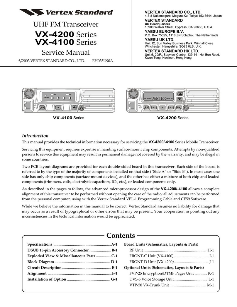
Vertex Standard VX-4200 Series User manual

Vertex Standard

Vertex Standard VX-4200 Series User manual

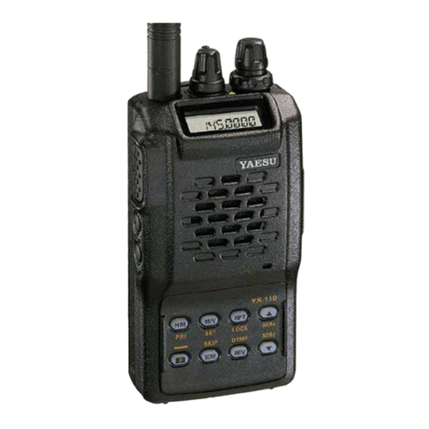
Vertex Standard VX-110 User manual

Vertex Standard

Vertex Standard VX-110 User manual

Vertex Standard VX-410 Series User manual

Vertex Standard

Vertex Standard VX-410 Series User manual

Popular Transceiver manuals by other brands

Yaesu FT-817ND Brochure & specs

Yaesu

Yaesu FT-817ND Brochure & specs

Yaesu FT DX 3000 operating manual

Yaesu

Yaesu FT DX 3000 operating manual

CIRCUIT DESIGN STD-302S Operation guide

CIRCUIT DESIGN

CIRCUIT DESIGN STD-302S Operation guide

Key Digital KD-PVB operating instructions

Key Digital

Key Digital KD-PVB operating instructions

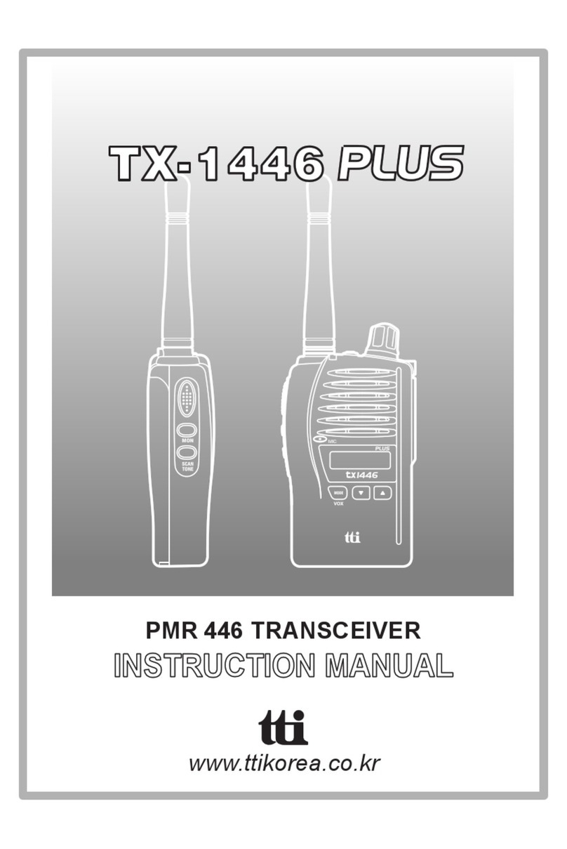
TTI TX-1446 Plus instruction manual

TTI

TTI TX-1446 Plus instruction manual

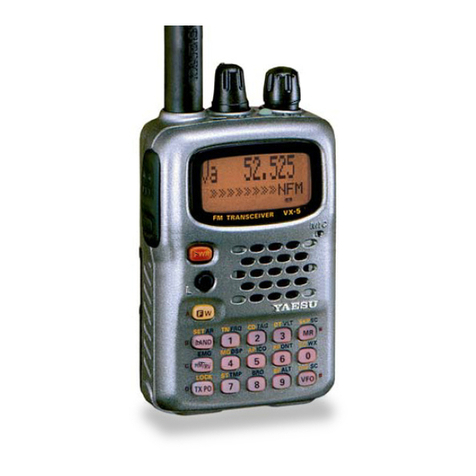
Yaesu VX-5R operating manual

Yaesu

Yaesu VX-5R operating manual

Intek seatec-5 owner's manual

Intek

Intek seatec-5 owner's manual

Yaesu FT-101E instruction manual

Yaesu

Yaesu FT-101E instruction manual

Yaesu FT-847 Technical supplement

Yaesu

Yaesu FT-847 Technical supplement

Yaesu Mark-V FT-1000MP Technical overview

Yaesu

Yaesu Mark-V FT-1000MP Technical overview

Kenwood Nexedge NX-5200 Service manual

Kenwood

Kenwood Nexedge NX-5200 Service manual

Kenwood TK-5210 instruction manual

Kenwood

Kenwood TK-5210 instruction manual

Maxon SMX-4150 Operator's manual

Maxon

Maxon SMX-4150 Operator's manual

Alinco DR-140T Service manual

Alinco

Alinco DR-140T Service manual

Yaesu FT-209R Technical supplement

Yaesu

Yaesu FT-209R Technical supplement

Alinco DR-510T Service manual

Alinco

Alinco DR-510T Service manual

Garmin G60 Important Safety and Product Information

Garmin

Garmin G60 Important Safety and Product Information

GEMTRONICS GTX-3325 Operation manual

GEMTRONICS

GEMTRONICS GTX-3325 Operation manual

manuals.online logo
manuals.online logoBrands
  • About & Mission
  • Contact us
  • Privacy Policy
  • Terms and Conditions

Copyright 2025 Manuals.Online. All Rights Reserved.