AnaCom AnaSat-Ku Series User manual

Standard-Ku
Extended-EKu
Super Extended-SEKu
Ku-Band Transceiver
Operating Manual
Rev 04
ANASAT®-Ku Series
ANACOM, INC

Ku-Band Transceiver
Operating Manual
ANACOM
Standard-Ku
Extended-EKu
Super Extended-SEKu
ANASAT®-Ku Series

©
2004 AnaCom, Inc. All rights reserved. The information furnished by AnaCom, Incorporated, in this publication is
believed to be accurate and reliable. However, no responsibility is assumed by AnaCom for its use, nor any
infringements of patents or other rights of third parties resulting from its use. No license is granted by implication or
otherwise under any patent or patent right of AnaCom, Inc. AnaCom reserves the right to change circuitry and
specifications at any time without prior notice.
The following terms are trademarks of their respective holders:
AnaSat, AnaCom, Inc.
Polyswitch
Teflon
Duroid
VT52, VT100 Digital Equipment Corp.
INTELSAT
ANACOM Inc.
150 Knowles Drive
Los Gatos, CA 95032
Tel: (408) 379-7482
Fax: (408) 379-7483
You have just received an AnaSat®-Ku Transceiver, a cost-effective product with no
compromise on quality and reliability. This product should provide tireless
performance in any reasonable operating environment.
We, at ANACOM, have taken great care to provide a convenient, easy-to-use product
in a single package. Our powerful Monitor and Control enables you to set transmit and
receive frequencies and gains and monitor numerous major and minor operational
parameters using a “dumb terminal” interface. There’s no need to worry about
available voltages; the internal universal power supply can automatically accommodate
virtually allAC voltage possibilities.
Should a situation arise beyond the operator’s control, just give us a telephone call.
Many situations can be diagnosed and solved by ANACOM’s trained customer-service
personnel over the phone.
If you have any questions, require technical assistance or training please call ANACOM
directly at (408) 379-7482 or FAX to us at (408) 379-7483. You can also send e-mail

ANACOM 3095604
ANACOM ANASAT®–KuTransceiver iii
Operating Manual
for the
ANASAT®-Ku-Series
Ku-Band Transceiver
Table of Contents
Subject Page
Section 1. Product Introduction and Specifications............................................. 1-1
Typical Operating Parameters ..................................................................................... 1-2
Section 2. Installation .............................................................................................. 2-1
Unpacking ................................................................................................................... 2-1
Packing List ................................................................................................................ 2-1
Safety Precautions ...................................................................................................... 2-2
Site Considerations ..................................................................................................... 2-2
Transceiver Mounting Considerations ........................................................................ 2-3
Grounding ................................................................................................................... 2-3
Cable and Waveguide Connections ............................................................................ 2-6
Water Resistance Wrap ............................................................................................... 2-8
Quick Start Guide ....................................................................................................... 2-9
Section 3. Operation ................................................................................................ 3-1
Preliminary Steps ........................................................................................................ 3-1
M & C Operation........................................................................................................ 3-2
GainAdjustments ........................................................................................................ 3-4
150 Knowles Drive, Los Gatosl CA 95032
Tel: (408) 379-7482 Fax: (408) 379-7483

ANACOM 3095604
iv ANACOM ANASAT®–Ku Transceiver
Subject Page
Section 4. Theory of Operation .............................................................................. 4-1
Signal Path .................................................................................................................. 4-1
Control & Power Systems .......................................................................................... 4-1
Low Noise Converter.................................................................................................. 4-1
Converter Module ....................................................................................................... 4-3
PowerAmplifier .......................................................................................................... 4-4
Monitor & Control Unit .............................................................................................. 4-5
Power Supply ............................................................................................................. 4-8
Section 5. Maintenance ........................................................................................... 5-1
LNC Replacement....................................................................................................... 5-2
Limited Warranty ......................................................................................................... 5-3
Appendices
AppendixA M & C Command Set .................................................................. A-1
Appendix B Alarm List ...................................................................................... B-1
Appendix C Serial Port Wiring ........................................................................ C-1
Appendix D Ku-Band Satellite Channel Frequencies
ANASAT®-Ku Transmit Channels .................................................. D-1
ANASAT®-EKu Transmit Channels ................................................ D-3
ANASAT®-SEKu Transmit Channels .............................................. D-5
ANASAT®-Ku, EKu, SEKu Receive Channels ............................... D-8
Appendix E Converting dBm to Watts and Watts to dBm ............................E-1
Appendix F Transceivers Weights & Dimensions ..........................................F-1

ANACOM 3095604
ANACOM ANASAT®–Ku Transceiver 1-1 Introduction
Section 1. Introduction
The ANASAT®-Ku transceiver upconverts the
modulator’s 70 MHz IF output to an RF signal in the
14 GHz range for transmission, and downconverts
the 12 GHz received RF signal to a 70 MHz IF signal
for use by the demodulator.
The PA uses Internally-Matched Field-Effect
Transistors (IMFET) to achieve highly linear power
and gain with minimal intermodulation distortion
(IMD) products.
High Electron Mobility Transistors (HEMT)
and Gallium-Arsenide Field-Effect Transistors (GaAs
FET) enable the Low-Noise Down-Converter
(LNC) to achieve a noise temperature better than
80ºK.
The transmit (TX) and receive (RX) synthesiz-
ers are locked to an oven controlled, high-stability
crystal oscillator (OCXO) and can provide 1 MHz
frequency selection step sizes over the entire band-
width. TX and RX frequency selection is completely
independent for extra flexibility.
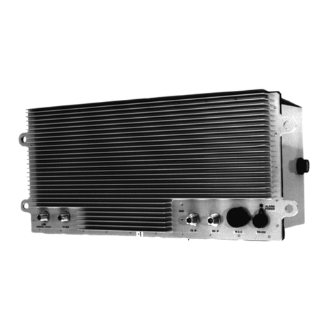
Figure 1-1 The ANASAT®-Ku VSAT transceiver (2W
version shown)
The ANASAT®-Ku VSAT series Ku-band
transceivers are designed for continuous outdoor
duty in all types of environments. Ideally suited for
SCPC, MCPC, and DAMA applications, the ANA-
SAT®-Ku series transceivers transmit in the 14 GHz
frequency range and receive in the 12 GHz range.
The ANASAT®-Ku VSAT transceivers inte-
grate all necessary functions, including the solid-state
power amplifier (PA), into a small, highly integrated
outdoor package. The only cabling required to the
indoor plant are the IF and AC power cables. The
LNC connects to the transceiver with a single co-
axial cable.
Designed to interface with any 70 MHz mo-
dem, the ANASAT®-Ku VSAT transceiver may be
used in a wide variety of communication networks.
The earth stations may be configured in Star, Mesh,
or Ring networks and with the optional Station Man-
agement System (SMS) tied to a PC, you can moni-
tor and control all local transceivers and other net-
work compatible equipment.
Figure 1-2. Another view of the ANASAT®-Ku

Introduction 1-2 ANACOM ANASAT®–Ku Transceiver
ANACOM 3095604
RF ELECTRICAL SPECIFICATIONS
A. FREQUENCIES
Model
(1) Transmit RF Ku 14.0 —14.5 GHz
WR-75 Flange (Threaded & Grooved) EKu 13.75 —14.25 GHz
SEKu 13.75 —14.50 GHz
(1 MHz step size; M & C Controlled)
(2) Receive RF 10.95 —12.75 GHz
(WR-75 Flange on LNC (1 MHz step size; M & C Controlled)
Threaded & Grooved)
(3) Transmit IF (N-connector) 52 to 88MHz (70 ± 18 MHz)
(4) Receive IF (N-connector) 52 to 88MHz (70 ± 18 MHz)
B. RF POWER LEVELS
(1) Receiver Output
Intermod. By-Product –35 dBc max.
with two carriers @ –89 dBm
30 kHz apart
(2) Transceiver Input –40 to –20 dBm; +10 dBm max.
(3) Transceiver Input
(a) + 25ºC at Transmit RF Connector
1dB COMP. PT 1dB COMP. PT
(0 dBm) 0 dBm min. (25 watt) 44 dBm min.
(2 watt) 33dBmmin. (40 watt) 46dBmmin.
(4 watt) 36dBmmin. (50 watt) 47dBmmin.
(8 watt) 39dBmmin. (60 watt) 47.8 dBm min.
(16 watt) 42 dBm min. (80 watt) 49 dBm min.
(20 watt) 43 dBm min. (100 watt) 50 dBm min.
(23 watt) 43.6 dBm min. (125 watt) 51 dBm min.
(b) Gain Variation, –40ºC to +50ºC @ Transmit RF and under all conditions ±1.5 dB
(c) Intermodulation By-Products (IP) (measured at a power
output of 9dB composite below the P–1dB spec) –30 dBc max.
(Two carriers at 9dB back-off)
C.RECEIVERGAIN
(1) Overall Gain (at +25ºC) 85 to 100 dB
(M & C controlled)
(2) Gain Variation under all conditions ±2 dB
Typical Operating Parameters

ANACOM 3095604
ANACOM ANASAT®–Ku Transceiver 1-3 Introduction
RF ELECTRICAL SPECIFICATIONS, (Con’t)
D. RECEIVER NOISE FIGURE (standard) 1.96 dB / 165ºK
(optional) 1.61 dB / 130ºK
(optional) 1.4 dB / 110ºK
E. INSTANTANEOUS BANDWIDTH
(1) Receiver RF to IF + 18 MHz for 70 MHz IF
(optional) + 36 MHz for 140 MHz IF
(2) Transmitter IF to RF + 18 MHz for 70 MHz IF
(optional) + 36 MHz for 140 MHz IF
F. IMPEDANCE
(1) Receiver Output 50W; (75Woptional)
(2) Transmitter Input 50W; (75Woptional)
G. SYNTHESIZERS (Transmitter and Receiver)
(1) Tuning Step Size 1 MHz (M & C controlled)
(2) Phase Noise (offset from carrier) –60 dBc / Hz @ 100 Hz
–70 dBc / Hz @ 1 kHz
–80 dBc / Hz @ 10 kHz
–90 dBc / Hz @ 100 kHz
H. FREQUENCYREFERENCE
Stability over temperature
–40ºC to +50ºC 1 x 10⁻⁸
Aging 1 x 10⁻⁹ / day
RF / IF CONNECTOR DESIGNATIONS
A. Receive Input on LNC WR-75 Flange (Threaded & Grooved)
B. Transceiver LNC Input N-Type-Female
C. LNC Output N-Type-Female
D. Receive IF N-Type-Female
E. Transmit IF N-Type-Female
F. Transmit Output WR-75 Flange (Threaded & Grooved)
INTERFACE ELECTRICAL SPECIFICATIONS
(1) Power Requirement 100 to 240 VAC
47--63 Hz
(2) Typical Power Consumption
0dBm 41VA 25 watt 302VA
2 watt 69VA 40 watt 767VA
4 watt 91VA 50 watt 804VA
8 watt 160VA 60 watt 853VA
16 watt 272VA 80 watt 1446VA
20 watt 294VA 100 watt 1617VA
23 watt 298VA 125 watt 1661VA

Introduction 1-4 ANACOM ANASAT®–Ku Transceiver
ANACOM 3095604
INTERFACE ELECTRICAL SPECIFICATIONS (Con’t)
(3) Prime Power Recommendation
0 dBm 100VA 25 watt 720VA
2 watt 175VA 40 watt 1690VA
4 watt 225VA 50 watt 1768VA
8 watt 400VA 60 watt 1876VA
16 watt 690VA 80 watt 3181VA
20 watt 700VA 100 watt 3557VA
23 watt 710VA 125 watt 3654VA
INTERFACE CONNECTION DESIGNATIONS
(1) Ports (Configurable) 2 each RS-232 or
1 RS-232 & 1 RS-485
(2) Protocol RS-232 port supports any “dumb” terminal orASCII interface
RS-485 port supports addressed packetized data
per ANACOM Supervisor™ software specifications
(3) Alarm Relays Form-C for Major and Minor alarms; isolated.
Independent TX and RX relay alarms in Protection Mode.
(4) Visual Indicators Flashing GREEN LED indicates active power
Flashing RED LED indicates summary alarm
MECHANICAL SPECIFICATIONS
A. WEIGHT
(1) Transceiver
0dBm 22 lbs (10.0 kg) max.
2W 26 lbs (11.8 kg) max.
4W 27 lbs (12.3 kg) max.
8W 28 lbs (12.7 kg) max.
16W 37 lbs (16.8 kg) max.
20W, 23W and 25W 40lbs (18.0 kg) max.
40W, 50W and 60W 67lbs (30.5 kg) max.
80W, 100W and 125W 123 lbs (55.8 kg) max.
(2) LNC 1.75 lbs (0.79 kg) max.
B. SIZE
(1) Transceiver
0dBm, 2W, 4W 21.6" x 9.0" x 7.0" (549 x 229 x 178 mm)
8W 21.6” x 9.0” x 11.6” (549 x 229 x 295 mm)
16W, 20W, 23W and 25W 21.6” x 9.0” x 13.0” (549 x 229 x 330 mm)
40W, 50W and 60W 21.6” x 13” x 13.6” (549 x 330 x 353 mm)
80W, 100W and 125W 34” x 11.5” x 13” (864 x 292 x 330 mm)
(2) LNC 8.4" x 2.9" x 1.75" - (213 x 74 x 44.4 mm)

ANACOM 3095604
ANACOM ANASAT®–Ku Transceiver 1-5 Introduction
MECHANICAL SPECIFICATIONS (Con’t)
C. SURFACE FINISH
Painted Surface
(a) Color (per FED-STD-595A, Spec. # 25630) Light Gray
(b) Final Coating: Powder
Unpainted Surfaces: Chem. Film per MIL-K-5541, Class 3
ENVIRONMENTAL SPECIFICATIONS
A.AMBIENTTEMPERATURE CONDITIONS
(1) Operating –40 to +50°C
(2) Storage –60 to +75°C
B.ALTITUDE 15000'ASLmax. (5000m)
C. RAIN 20" / hour (508mm/hr)
D. WIND 150 MPH (250km/hr)
E.VIBRATION
(1) Operating 1.0 G random
(2) Survival 2.5 G maximum random
F. SHOCK
(1) Operating 10G
(2) Survival 40Gmax.
NOTE: Operating parameters subject to change without notice.

Introduction 1-6 ANACOM ANASAT®–Ku Transceiver
ANACOM 3095604

ANACOM 3095604
ANACOM ANASAT®–Ku Transceiver 2-1 Installation
Section 2. Installation
The ANASAT®-Ku transceiver consists of the
transceiver, the Low Noise Converter (LNC), and
the LNC interconnection cable.
This chapter contains the general requirements
for installing the transceiver and LNC on the antenna
and making the cable and waveguide connections.
Specific mounting methods may vary considerably
depending upon particular antenna and site charac-
teristics. Refer to the antenna manufacturer’s in-
structions for more detailed instructions.
ANASAT®-Ku transceivers are designed for
installation and setup without removing the cover.
The transceiver may be completely initialized for nor-
mal operation using an ASCII
terminal or a local computer.
Table 2-1. ANASAT®-Ku Packing List
!
Removal of any cover may jeopardize
the weather seal which may cause
problems later.
Unpacking
Check to make sure that the transceiver has
not suffered any damage in shipment. Compare con-
tents of the crate to ensure items received match
those listed on the packing slip. Retain all shipping
containers for future use.
Tools and Test Equipment
Have on-hand a standard electrician’s tool kit
and any tools listed in your antenna installation in-
structions.
Unit Part Number Quantity
• Transceiver — 1
• LNC, wide mouth 30784 1
Accessory Kit for Ku-Band:
• 10 ft. (3m) LNC to Transceiver Cable with
male N-connectors (longer cables also available) 31198-010 1
• Power Cable with 4-pin circular connector (one end) 31185 1
• Cable-End Connectors:
6-pin weathertight circular 10614006 1
18-pin weathertight circular 10616018 1
• Supervisor Software CD 30673 1
• 10 ft. (3m) M&C 6 Pin to DB-9 Pin RS232 Cable 30720-010 1
• LNC Screws
Screw, 6-32 x 7/16" 11806007 5
Washer, 6-32, Flat #6 11811001 5
Washer, 6-32, Split #6 11815001 5
Nut, 6-32 11819002 5
O-Ring Gasket 10950 1
• Operating Manual 30956 1
• Quick Start Guide 1
Optional Accessories:
• Transceiver Mounting Kit, TX Reject Filter Contact Factory
ANASAT®-Ku Packing List

ANACOM 3095604
Installation 2-2 ANACOM ANASAT®–Ku Transceiver
LNC
Be sure the LNC unit is properly terminated
prior to operation. Ensure all the correct waveguide
gaskets are used to prevent water damage.
Site Considerations
Peculiar installation requirements of any par-
ticular site is the responsibility of the system opera-
tor. ANACOM can engineer an optional installation
mounting kit, customized for your site and hardware.
Contact ANACOM for details.
Antenna
The transceiver must be attached to some form
of mounting structure which is usually the antenna
feed boom or the antenna bracket structure. Specific
mounting procedures will depend on the antenna
used. The transceiver and LNC are designed to be
mounted on most antennas. Locate and install the
antenna according to the antenna manufacturer’s
instructions. Choose an area that is free of extrane-
ous interference from motors and electronic equip-
ment and has a clear line-of-sight from the antenna
to the satellite.
Lightning arrestors should be used at the site to
protect personnel and equipment. Size 3/0 or 4/0
stranded copper wire should be used to bond the
transceiver to the antenna frame and to the lightning
protection ground rod.
Power Requirements
The ANASAT®-Ku transceiver requires a
power source which supplies 110 VAC or 220 VAC
at 50 or 60 Hz, through a circuit breaker. Size of cir-
cuit breaker depends on model. To assure uninter-
rupted service, some method of back-up AC power
is recommended. Installing surge arrestors and AC
power line filters will reduce voltage surges from the
AC power input. Provide an isolation filter to clean
up power line interference and/or voltage variations,
as required.
NOTE: AC TRANSIENTS AND SURGES MAY CAUSE DATA TRANSMISSION ER-
RORS AND LOSS OF SYNCHRONIZATION IN THE TRANSCEIVER SYNTHESIZERS
AND/OR THE EXTERNAL MODEM EQUIPMENT.
Safety Precautions
General
Ensure the ANASAT®-Ku transceiver and
LNC are properly grounded. Do not rely on coaxial
cable shields for the ground connection.
If the cover is removed from any ANACOM
product, ensure that all:
•gaskets are intact and free of damage prior
to reinstallation
•mounting screws are properly installed
Ensure all connectors are properly water-
proofed.
Power Supply
Confirm that AC Power is disconnected before
removing the transceiver or LNC cover.
Transceiver
Take adequate precautions to ensure the
ANASAT®-Ku transceiver does not transmit a signal
until it has been properly connected and set up for
authorized frequencies and power levels. The trans-
mitter is normally shipped from the factory with TX
ON!
!
Observe normal safety precautions
when operating this equipment.
Transmitter RF output power levels
are adequate to cause blindness or
other serious injury to body tissues.
Use caution when working around
the transceiver or antenna when the
transmitter is active.
!
Power Amplifier
Be sure the transceiver TX OUT port is prop-
erly terminated prior to operation. Ensure all the cor-
rect waveguide gaskets are used to prevent water
damage.
TO ENSURE PROTECTION OF PERSONNEL
AND EQUIPMENT, USE CARE DURING AN-
TENNA INSTALLATION AND WHENEVER
WORKING ON OR AROUND THE SYSTEM.

ANACOM 3095604
ANACOM ANASAT®–Ku Transceiver 2-3 Installation
Transceiver Mounting
Considerations
The ANASAT®-Ku transceiver must be
mounted such that:
1. Sufficient support is afforded the transceiver
to minimize the effects of antenna sway in
strong winds.
2. Air movement is possible across the heat
sink fins. Ideally, the fins should be aligned
vertically, but this is not required.
NOTE: The length (and associated RF losses)
of the interconnecting cables must be considered
when determining the location of the transceiver and
LNC.
Transceiver Mounting
The ANASAT®-Ku transceiver is designed for
mounting in any position. For optimal heat sink action,
the heat sink fins should be vertical, or as nearly ver-
tical as is practical. For transceivers equipped with a
fan, this suggestion does not apply.
Figure 2-1 shows a common installation ex-
ample where the transceiver is mounted on the an-
tenna feed support arm.
When mounting the transceiver, allow enough
room to adjust the antenna’s azimuth and elevation.
Throughout installation and during any polarization,
azimuth, or elevation adjustment, ensure the cables
and waveguide are not crimped or pinched.
Figures 2-1a and 2-1b in next pages shows the
transceiver mounting for single thread.
Grounding
Electrical bonding (grounding) of the trans-
ceiver is required to prevent possible damage from
lightning or other induced electrical surges.
The transceiver is provided with both an M3,
and a #8 ground point. It is recommended that 000
AWG copper wire or copper braid be used to bond
this unit to the earth ground (grounding rod) using the
most direct (shortest) route possible.
LNC/TR Filter Mounting
The LNC is shown in Figure 2-2. The LNC is
directly bolted to the antenna RX feed. An appropri-
ate waveguide gasket must be included at the feed
point. Connect one end of the coaxial cable with
male N-connectors (included) to the LNC. Refer to
the note at the end of this section regarding water-
tight connections. Route the 10-foot cable to the
transceiver and connect to the LNC N-connector.
Longer cable lengths may be used under certain cir-
cumstances; contact ANACOM for details.
Caution: Never touch the ground-plane an-
tenna pin found inside the wave-guide flange of the
LNC. The front-end preamp is susceptible to static
discharge.
Figure 2-1. Typical transceiver mounting.
Ku-BAND FEED
TRANSCEIVER
MOUNTING KIT
2.4m 2-piece 0.6 f/d
antenna

ANACOM 3095604
Installation 2-4 ANACOM ANASAT®–Ku Transceiver
Figure 2-1a Transceiver Mounting for Single Thread

ANACOM 3095604
ANACOM ANASAT®–Ku Transceiver 2-5 Installation
Figure 2-1b Transceiver Mounting for Single Thread

ANACOM 3095604
Installation 2-6 ANACOM ANASAT®–Ku Transceiver
2. Transmitter Feed
Referring to Figure 2-4, connect a section of
waveguide between the OMT transmit port
and the transceiver’s transmit output, TX
OUT. Waveguide should be attached to the
antenna feed per manufacturer’s instructions.
Ensure a gasket is fitted at each flange and
that the connections are weather-tight.
3. 70MHz Modem
Attach a coaxial cable with male N-connec-
tors between the transceiver’s TX IF (see
Figure 2-5) and the modulator IF OUTPUT.
Make sure that the connections are weather-
tight.
Attach a coaxial cable with male N-connec-
tors between the transceiver’s RX IF (see
Figure 2-5) and the demodulator IF INPUT.
Make sure that the connections are weather-
tight.
Cable and Waveguide
Connections
Cabling Requirements
Local regulations may require that cables in oc-
cupied buildings be installed in steel conduit. Local
government agencies may waive this requirement for
the use of Plenum cables, which are standard cables
entirely encased in solid Teflon. Check the codes in
your area.
NOTE: EQUIPMENT OUTAGES DUE TO FAULTY CABLE
MATERIALS OR INSTALLATION ARE NOT COVERED BY YOUR
WARRANTY.
Figures 2-3, 2-4, and 2-5 provides the cabling
diagram for the ANASAT®-Ku transceiver.
1. AC Power
Attach the AC input cable to the 4-pin con-
nector on the transceiver. Run the AC cable to
the power source but do not attach. The sup-
plied power cable has a four-pin weather-tight
circular connector attached to one end. The
other end is terminated with flying leads. At-
tach the proper AC power connector for your
location to the other end of this cable.
Color code:
Brown..................AC Hot power lead
Blue......................AC Neutral power lead
Green/Yellow......Ground
Figure 2-2. LNC assembly.
Figure 2-3. AC Power Connection.

ANACOM 3095604
ANACOM ANASAT®–Ku Transceiver 2-7 Installation
Waveguide to transmit
antenna interface
(WR-75 flange) AC Power
(side mounted
4-pin circular
connector)
Cable to LNC
LNC Input
(N-female)
Ground Lug See detail, below
Figure 2-5. ANASAT®-Ku Cabling Interconnections M & C and IF Connections close-up.
Ground Lug
RS-232 to terminal
(6-pin circular)
RS-485/RS-232
plus alarm output to terminal
(18-pin circular)
70MHz TX IF Input
(N-female)
70MHz RX IF Output
(N-female)
Status LEDs:
Red—ALARM
Flashing Green—“OK”
Figure 2-4. ANASAT®-Ku Cabling Interconnection Diagram for the entire transceiver.

ANACOM 3095604
Installation 2-8 ANACOM ANASAT®–Ku Transceiver
4. LNC
Attach the RF cable between the LNC con-
nector and the transceiver LNC input
connector(refer to Figure 2-4). If a longer
cable is required, ensure that the replacement
cable is designed for low loss at microwave
frequencies. Maximum loss of the LNC cable
must be 10 dB or less at 10 GHz!
5. Terminal Connections
A data terminal or a computer with terminal
software connects to the ANASAT®-Ku via
either RS-232 or RS-485 serial ports. Appen-
dix C shows the pinout of the serial outputs.
Both 6-pin and 18-pin weather-tight circular
connectors are included. An optional serial
computer cable is available from ANACOM.
Final Check
Recheck all bolts and cabling. Refer to Figures
2-3, 2-4, and 2-5 to verify cable connections.
After all other connections have been made,
connect the AC power cord to an active outlet.
Water Resistance Wrap
The application of moisture-resistant wrap
(mastic tape) to all connectors is recommended to
prevent water entry and resultant water damage.
See Figure 2-6. Apply the mastic tape as follows:
1. Ensure that all connectors are tight.
2. Pre-cut the mastic tape to the desired size
and remove the protective wax liner from
the tape.
3. Center the tape on the connector to be
sealed and wrap the tape tightly around the
connector. Squeeze the tape tightly and en-
sure that both ends of the tape have formed
around the connector and the cable.
4. Apply the mastic tape to all connectors that
may be exposed to moisture.
Figure 2-6. Mastic Tape application

ANACOM 3095604
ANACOM ANASAT®–Ku Transceiver 2-9 Installation
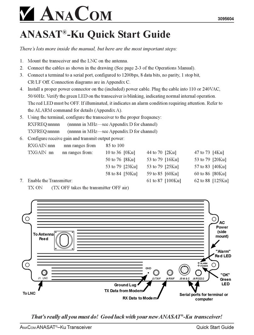
ANASAT®-Ku Quick Start Guide
There’s lots more inside the manual, but here are the most important steps:
1. Mount the transceiver and the LNC on the antenna.
2. Connect the cables as shown in the drawing (See page 2-3 of the Operations Manual).
3. Connect a terminal to a serial port, configured to 1200bps, 8 data bits, no parity, 1 stop bit,
CR/LF Off. Connection diagrams are in Appendix C.
4. Install a proper power connector on the (included) power cable. Plug the cable into 110 or 240VAC,
50/60Hz. Verify the green LED on the transceiver is blinking, indicating normal internal operation.
The red LED must be OFF. If illuminated, it indicates an alarm condition requiring attention. Refer to
the ALARM command for details (Appendix A).
5. Using the terminal, configure the transceiver to the proper frequency:
RXFREQ nnnnn (nnnnn in MHz—see Appendix D for channel)
TXFREQ nnnnn (nnnnn in MHz—see Appendix D for channel)
6. Configure receive gain and transmit output power:
RXGAIN nnn nnn ranges from 85 to 100
TXGAIN nn nn ranges from: 10 to 36 [0Ku] 44 to 70 [2Ku] 47 to 73 [4Ku]
50 to 76 [8Ku] 53 to 79 [16Ku] 53 to 79 [20Ku]
53 to 79 [23Ku] 53 to 79 [25Ku] 57 to 83 [40Ku]
58 to 84 [50Ku] 59 to 85 [60Ku] 60 to 86 [80Ku]
7. Enable the Transmitter: 61 to 87 [100Ku] 62 to 88 [125Ku]
TX ON (TX OFF takes the transmitter OFF air)
J3 TXIF J4 RXIF J5 M & C J6 R S232
ALARM
POWER
J1 LNB
GND
AC
Power
(side
mount)
To LNB
To Antenna
Fe e d
TX Data from Modem
RX Data to Mode m Serial ports for terminal or
computer
Ground Lug
"OK"
Gr e e n
LED
"Alarm"
Re d LED
To LNC
J1 LNC
This manual suits for next models
3
Table of contents
Other AnaCom Transceiver manuals