TowerIQ GuardianB 1/2W User manual

Document 5403795 Rev A
5/23
GuardianB™1/2W (3996134)
Class B Public Safety BDA
For First Responders
Long Island City, NY, 11101
https://toweriq.nyc
© 2021 TowerIQ, Inc.

FCC NOTICE
The TowerIQ GuardianB 1/2W" signal booster is Class B booster. Under Section 90.219(d)(5) of the Commission’s rules, all Part 90 Class B signal
booster installations must be registered with the FCC.
NOTE: This equipment has been tested and found to comply with the limits for a Class A digital device, pursuant to part 15 of the FCC Rules.
These limits are designed to provide reasonable protection against harmful interference in a commercial environment. This equipment generates,
uses and can radiate radio frequency energy and, if not installed and used in accordance with the instructions, may cause harmful interference to
radio communications. Operation of this equipment in a residential area is likely to cause harmful interference in which the user will be required to
correct the interference at his own expense.
Filing Registrations. To register a Part 90 Class B signal booster, go to the Part 90 Signal Booster Registration and Discovery page at www.fcc.
gov/signal-boosters/registration. Enter an FCC Registration Number (FRN) and Password in the upper-right corner of the screen. Then click on
“LOGIN.”
On the Signal Booster Information page, enter either (1) latitude and longitude (in decimal degrees) of the booster location and click on the “Get
Address Info” button; or (2) the booster, city, and state, and click on the “Get Lat/Long button. The registration tool will provide a map of the booster
location to verify the location is correct. Next, check the box(es) for the frequencies within the operating range of the signal booster and enter at
least one call sign associated with the booster. Then enter the filer’s Company Information (Company Name, Company Attention, Address, Email
registration, enter Signature Information (Title, Name), and click “Submit.” The system will generate a confirmation, including a booster ID number,
which you may print for your records. Each booster must be submitted separately. Using the links in the upper-right corner of the Signal Booster
Confirmation page, you can “Add a Booster,” “View Your Boosters” or “Log out.”
Accessing Registrations. Each registration will be available to the public on the same day it is filed with the Commission. Registrations may be
accessed at: www.fcc.gov/signal-boosters/registration. Click on “View All Boosters” from the Part 90 Signal Booster Registration and Discovery
page. The registrations can be searched and sorted by booster ID number, name of the filer, city, county, state, zip code, latitude/longitude, or call
sign.
For further information please contact the FCC Licensing Support Hotline at (877) 480-3201 or submit an online help request at https://esupport.
fcc.gov/onlinerequest.htm. Support hours are Monday thru Friday, 8:00–6:00 p.m. Eastern Time, except for Federal holidays.
Applicant's name: TowerIQ, Inc.
Address: 13723 Riverport Drive
C/O Potter Electric Signal Company
Saint Louis, MO 63043
FCC Contact information is https://signalboosters.fcc.gov/signal-boosters/ Federal Communications Commission
45 L Street NE Washington, DC 20554
Phone: 1-888-225-5322
TTY: 1-888-835-5322

GUARDIANB 1/2W" • 5403795 REV A • 5/23
3
Table of Contents
Chapter 1: Introduction & Overview....................................................................................................................... 4
1.1 Product Overview......................................................................................................................................... 4
1.2 Package Contents........................................................................................................................................ 4
1.3 Additional Items Needed .............................................................................................................................. 4
1.4 Key Features & Benefits ............................................................................................................................... 4
1.5 Optional Accessories.................................................................................................................................... 5
1.6 How it Works ............................................................................................................................................... 6
1.7 A Word About Safety.................................................................................................................................... 6
Chapter 2: BDA Interface & Connections .............................................................................................................. 7
2.1 GuardianB 1/2W BDA Interface Overview ..................................................................................................... 7
2.2 ON/OFF Switch............................................................................................................................................ 8
2.3 RF Interfaces (A6 & A1) ................................................................................................................................ 8
2.4 Power Wiring for AC and DC Power for 24V UPS/Battery Backup ................................................................. 8
2.5 GUI Interface................................................................................................................................................ 9
2.6 Fire Alarm I/O Interface................................................................................................................................. 9
2.7 VSWR Alarm Trigger Criteria ....................................................................................................................... 10
2.8 Oscillation Detected Alert Trigger Criteria .................................................................................................... 10
2.9 Component Alert Trigger Criteria................................................................................................................. 12
2.10 Load Restrictions ..................................................................................................................................... 12
2.11 Ethernet Interface .................................................................................................................................... 12
2.12 USB Interface .......................................................................................................................................... 12
2.13 Alarm LEDs ............................................................................................................................................. 12
Chapter 3: Planning the Installation..................................................................................................................... 14
3.1 Installation Overview................................................................................................................................... 14
3.2 Exterior Antenna Overview.......................................................................................................................... 14
3.3 Interior Antenna Overview........................................................................................................................... 15
3.4 Antenna Separation.................................................................................................................................... 16
3.5 BDA Location ............................................................................................................................................ 16
3.6 Accessories ............................................................................................................................................... 17
3.7 Need Help?................................................................................................................................................ 17
Chapter 4: Installation ......................................................................................................................................... 18
4.1 Soft Installation .......................................................................................................................................... 18
4.2 Exterior Antenna ........................................................................................................................................ 18
4.3 Interior Antennas........................................................................................................................................ 19
4.4 Mounting the BDA...................................................................................................................................... 20
Chapter 5: Configuration & Testing...................................................................................................................... 20
5.1 Powering on the BDA................................................................................................................................. 20
5.2 DIP Switch Configuration............................................................................................................................ 21
Chapter 6: Testing And Troubleshooting.............................................................................................................. 23
6.1 Band LED Conditions ................................................................................................................................. 23
6.2 LED Conditions.......................................................................................................................................... 23
6.3 Testing & Troubleshooting........................................................................................................................... 23
Chapter 7: Sentry Configuration & Monitoring..................................................................................................... 24
7.1 Sentry Software Introduction ...................................................................................................................... 24
7.2 Software Installation ................................................................................................................................... 24
7.3 Hardware Installation.................................................................................................................................. 24
7.4 User Registration ....................................................................................................................................... 25
7.5 Device Registration .................................................................................................................................... 26
7.6 Device Configuration .................................................................................................................................. 26
7.7 Sentry Operation........................................................................................................................................ 27
Chapter 8: Specifications .................................................................................................................................... 29
Chapter 9: Safety And Compliance ..................................................................................................................... 30
9.1 FCC Compliance ....................................................................................................................................... 30
Chapter 10: Warranty .......................................................................................................................................... 31
10.1 Warranty Periods .......................................................................................................................................... 31
10.2 Three-Year Product Warranty.................................................................................................................... 31
10.3 Limitations of Warranty, Damages and Liability .......................................................................................... 31

GUARDIANB 1/2W" • 5403795 REV A • 5/23
4
Introduction & Overview
CHAPTER 1: INTRODUCTION & OVERVIEW
1.1 Product Overview
GuardianB 1/2W is a Class B, "1/2"-watt, bi-directional amplifier with a maximum gain of 80 dB supporting both the 700 and 800 MHz Public Safety frequency
bands.
In the majority of cases, newly constructed buildings with considerable size, or existing buildings that increase capacity by expanding the building footprint are
required to have signal strength of -95 dBm or better in designated critical areas – Emergency Command Centers, Fire Pump Rooms, stairwells, standpipe,
cabinets, etc. – in order to receive a certificate of occupancy. Guardian B meets the code for NFPA 72/1221 and IFC 510 and features a Type 4 rated amplifier
housing.
Additionally, the GuardianB comes equipped with integrated alarming compatibility, UPS and Ethernet enabled remote monitoring. TowerIQ provides an industry
leading 3-year warranty
1.2 Package Contents
Your BDA box contains the following items:
• GuardianB bi-directional amplifier with Type 4 rated housing and mounting kit
• Integrated alarm cable (5 ft)
1.3 Additional Items Needed
The GuardianB needs the following additional components for a complete install:
• One External antenna (directional Yagi)
• Multiple Inside antennas (omnidirectional domes and/or directional panels)
• Cable splitter for inside antennas
• Sufficient lengths of ultra-low loss interior/exterior cable, 50-ohm
• Lightning surge arrestor
• Grounded surge suppressor for DC power supply
• Ethernet cable
Note: Some component options are listed in table below. Not all accessories are listed.
1.4 Key Features & Benefits
• Improves coverage for Public Safety Band cellular network frequencies: (UL: 788-805, 806-816MHz | DL: 758-775, 851-861MHz)
• 80 dB gain, 1/2 W system
• UL2524 Certified
• Meets the code for NFPA 72/1221 and IFC 510
• Type-4 rated amplifier housing. No additional Type 4 enclosure needed
• Supplementary ethernet port with built-in TowerIQ Sentry™ remote monitoring hardware
• Integrated alarming
• Connects to UL2524 LIsted UPS for external battery backup
• Automatic gain control (AGC) and Oscillation Detection
• Energy-saving operation allows bands to remain dormant when not in use
• A/C 110V and D/C 24V power option
• Independently adjustable frequency attenuation for uplink and downlink (Reduce gain in -1 dBm increments)
• Industry leading 3-year warranty
GUARDIANB 1/2W" • 5403795 REV A • 5/23
5
1.5 Optional Accessories
TowerIQ provides many optional features and accessories for the GuardianB Amplifier. Note, some component options are listed in table below. Not all
accessories are listed.
See your TowerIQ sales person for all compatible part numbers
Outdoor Antenna Options
3996048 - Directional Wide Band 50Ω Yagi Antenna (698-960 MHz); N-Female connectors; 8 dBi. Note: Must use at least 2 dB insertion loss
Inside Antenna Options
3996140 - Omni-directional Wide Band 50 Ω Dome Antennas (698 -960 MHz); N-Female connectors; 3 dBi
3996141 - Directional Wide Band 50 Ω Panel Antennas (698-960 MHz); N-Female connectors; 6 dBi. Note: Must use at least 4 dB insertion loss cable for this option
Note: The sum of antenna gain (dBi) and cable loss (dB) cannot exceed 2.
Ultra Low-Loss Coaxial Cable
3996129 - Trilogy 1/2 inch air dielectric plenum rated cable
Splitters, Couplers & Accessories
Wide Band Couplers (698-2700 MHz)
Wide Band Splitters (698-2700 MHz)
TQ-LP Lightning Protector
5 dB; 10 dB; 20 dB RF Attenuator
TQ-Mount-Pole: L Bracket mount with U bolt hardware for donor antenna mount to J-bar
TQ-Mount-JBar: Steel 1 inch J-Bar mount for donor antenna. Antenna mount not included
TowerIQ’s fire-rated plenum cable is UL-rated for plenum ceilings (UL E473791)
Introduction & Overview
GUARDIANB 1/2W" • 5403795 REV A • 5/23
6
1.6 How it Works
The GuardianB amplifies signals that reach a building from the nearest radio tower, and from radios inside the building going back to the tower. This compensates
for weak reception caused by distance, topography, building structure, etc. The BDA receives the signal from an outside antenna, amplifies that signal, and then
rebroadcasts it via antenna(s) inside the building, where it can then be picked up by radios inside. In the reverse direction, interior antennas also pick up signals
coming from radios, where they are amplified by the BDA, and then passed to the exterior antenna for rebroadcast back to the tower.
1.7 A Word About Safety
Follow all safety precautions in this manual. This information is designed to prevent personal injury, equipment malfunction, and/or radio interference. You are
responsible for ensuring a safe installation.
Your installation may require working in high locations such as roofs and/or ladders. Follow applicable safety regulations and best practices to avoid falling.
Take care not to drop objects from any high area. Cordon off ground areas directly below the section of roof you are working on, or below your ladder whenever
possible.
In addition, as a qualified installer, you are responsible for knowing and following all applicable codes and regulations and for obtaining all required permits and
inspections.
Always use appropriate personal protective equipment such as goggles, gloves, hard hat, etc. as needed, and as required. Failure to exercise caution when
working in high areas could cause a fall and personal injury.
.
RF SAFETY WARNING: ANY ANTENNA USED WITH THIS DEVICE MUST
BE LOCATED AT LEAST 8 INCHES FROM ALL PERSONS.
CHANGES OR MODIFICATIONS NOT EXPRESSLY APPROVED BY
TOWERIQ COULD VOID THE USER’S AUTHORITY TO OPERATE THE
EQUIPMENT.
1.8 Warning Notices:
Caution: notices may also be used in this manual to draw attention to matters that do not constitute a risk of causing damage to the equipment but where there
is a possibility of seriously impairing its performance, e.g. by mishandling or gross maladjustment. Warnings and Cautions within the main text do not incorporate
labels and may be in shortened form.
These draw the attention of personnel to hazards that may cause damage to the equipment. An example of use is the case of static electricity hazard.
Caution: Risk of explosion if battery is replaced by an incorrect type. Dispose used batteries according to the instructions.
Disconnection of the 2 RF connectors may cause damage to the equipment when power is on. The application antenna and RF cable are not provided. The sum
of antenna gain (dBi) and cable loss (dB)should not exceed 3 dB for inside antenna and 9 dBi for outside antenna, shortest distance from human is 0.805m
Important: Unauthorized antenna cables and/or coupling devices may not be used. Changes or modifications not expressly approved by the TowerIQ could void
the user’s authority to operate the equipment.
Use of unauthorized antennas, cables, and/or coupling devices not conforming with ERP/EIRP and/or indoor only restrictions is prohibited
Home/ personal use are prohibited.
Note: If the insertion loss of the outside cable exceeds 3dB, the VSWR alarm will be affected.
Introduction & Overview

GUARDIANB 1/2W" • 5403795 REV A • 5/23
7
CHAPTER 2: BDA INTERFACE & CONNECTIONS
2.1 GuardianB 1/2W BDA Interface Overview
Interface Type Description
A1 INSIDE N Female for INSIDE cable and antenna
A2 ETHERNET Cat5e Standard Ethernet Cable Device
A3 ALARM I/O To Fire Department Control Box
A4 DC INPUT Connect UPS, voltage range is 18.5-29V; DC power is the secondary power supply, and secondary
power (DC input) source shall be UL2524 listed.
A5 OUTSIDE N Female for OUTSIDE cable and antenna
A6 USB Used to initialize the network connection devices
A7 GROUNDING LUG Grounding lug
A8 POWER 110 VAC Connect to 110VAC or 110V of UL2524 listed UPS
A9 ALARM LEDs Indicate an alarm condition
BDA Interface & Connections
GUARDIANB 1/2W" • 5403795 REV A • 5/23
8
BDA Interface & Connections
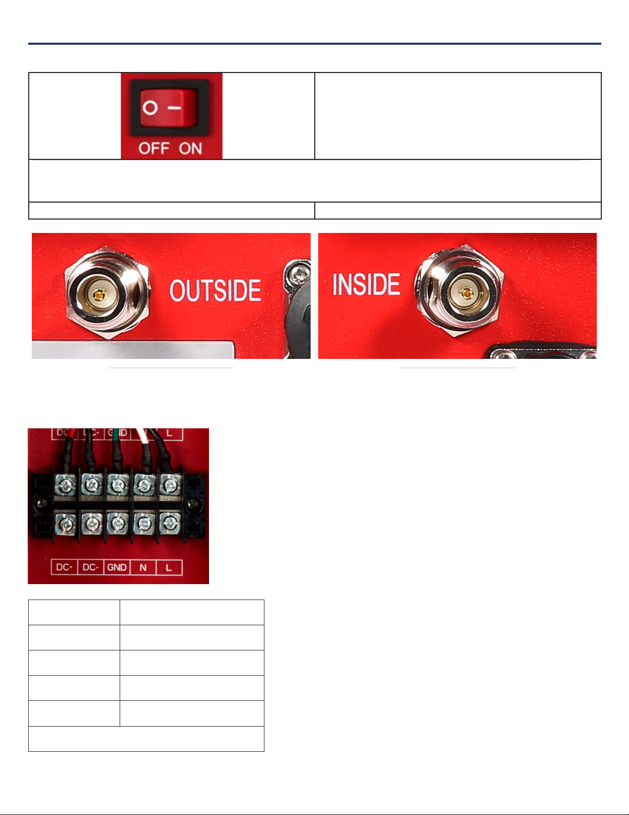
2.2 ON/OFF Switch
An ON/OFF switch is used to cut off the connection between RF module and both the DC input and the power supply output." with a
ON/OFF switch picture.
2.3 RF Interfaces (A6 & A1)
A6 — N-type Female for OUTSIDE
cable and antenna
A1 — N-type Female for INSIDE
cable and antenna
2.4 Power Wiring for AC and DC Power for 24 UPS/Battery Backup
DC+ Battery positive input (Red)
DC- Battery negative input (Black)
GND Ground (Green)
NAC N input (White)
LAC L input (Black)
Wire Gauge: 14 to 22 AWG
Note: 1/4" spacing is to be maintained between power limited and non-power limited Circuits
BDA Interface & Connections

GUARDIANB 1/2W" • 5403795 REV A • 5/23
9
2.5 GUI Interface
GUI interfaces are for firmware update.
GUI1 is for Sentry Board; GUI2 is for RF board.
2.6 Fire Alarm I/O Interface
Number Definition
Wire Color on Cable
1VSWR Alert (N.O.) Black
2VSWR Alert (COM) Red
3VSWR Alert (N.C.) White
4Oscillation Detected Alert (N.O.) Green
5Oscillation Detected Alert (COM) Brown
6Oscillation Detected Alert (N.C.) Blue
7Component Alert (N.O.) Yellow
8Component Alert (COM) Purple
9Component Alert (N.C.) Gray
BDA Interface & Connections
Note: these connections need to be made to Power Limited sources.
GUARDIANB 1/2W" • 5403795 REV A • 5/23
2.7 VSWR Alarm Trigger Criteria
The VSWR Alarm is triggered under the following:
• VSWR Alarm caused by outdoor VSWR abnormal
N.C.
N.O.
COM
N.C.
N.O.
COM
Relay Shown In Non-Alarm Condition for N.C. Alarm Condition for N.C.
N.C.
N.O.
COM
N.C.
N.O.
COM
Relay Shown In Non-Alarm Condition for N.O. Alarm Condition for N.O.
10
BDA Interface & Connections
GUARDIANB 1/2W" • 5403795 REV A • 5/23
11
BDA Interface & Connections
2.8 Oscillation Detected Alert Trigger Criteria
The Oscillation Detected Alert is triggered undeR the following conditions:
• The isolation between outside antenna and inside antenna is not enough.
N.O.
N.C.
COM
Alarm Condition for N.C.
N.O.
N.C.
COM
Relay Shown In Non-Alarm Condition for N.O.
N.O.
N.C.
COM
Alarm Condition for N.O.
N.O.
N.C.
COM
Relay Shown In Non-Alarm Condition for N.C.
GUARDIANB 1/2W" • 5403795 REV A • 5/23
12
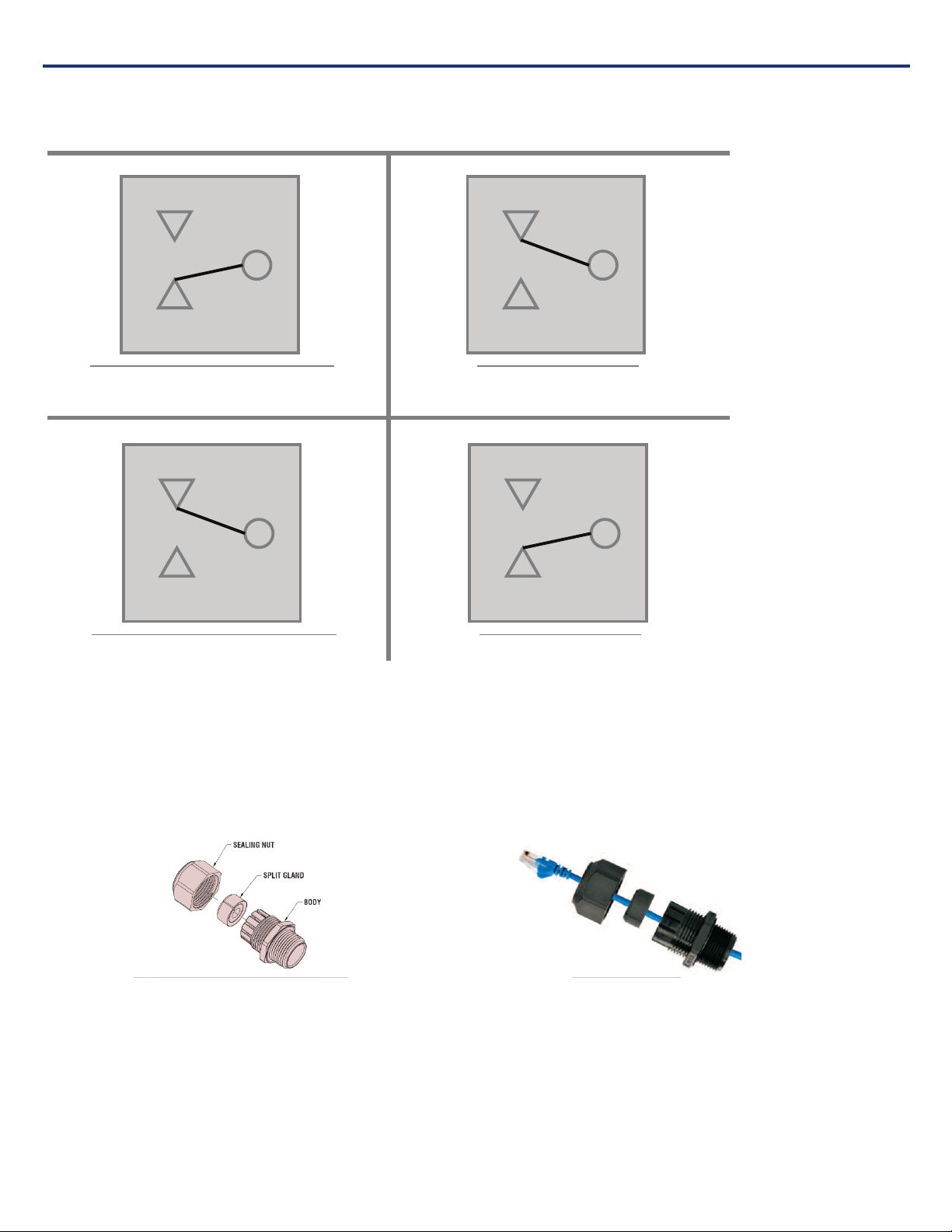
2.11 Ethernet Interface
Ethernet Connector Assembly Drawing Ethernet Connector
BDA Interface & Connections
2.9 Component Alert Trigger Criteria
The Component Alert is triggered under the following:
• Repeater current is abnormal
2.10 Load Restrictions
Alarm Dry Contact Output Restrictions: 1 A at 30 VDC (Resistive)
Note: these connections need to be made to Power Limited sources.
N.O.
N.C.
COM
Alarm Condition for N.C.
N.O.
N.C.
COM
Relay Shown In Non-Alarm Condition for N.O.
N.O.
N.C.
COM
Alarm Condition for N.O.
N.O.
N.C.
COM
Relay Shown In Non-Alarm Condition for N.C.
GUARDIANB 1/2W" • 5403795 REV A • 5/23
13
BDA Interface & Connections
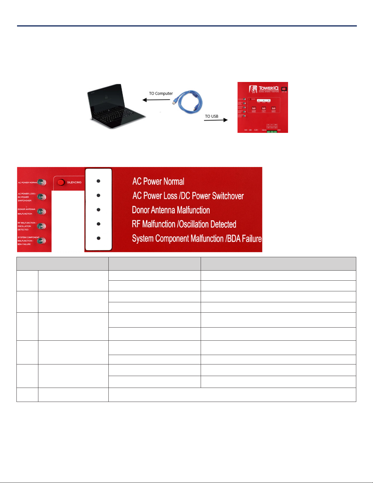
2.13 Alarm LEDs
Status Description
1 AC Power Normal
Green ON AC Power is working properly
OFF
2AC Power Loss /DC Power
Switchover
Red ON AC Power is not working, and BDA has switched to DC Power.
OFF
3 Donor Antenna Malfunction
Red ON Connection to the donor antenna has been interrupted or is not
present. Possible bad connector or cable termination.
OFF
4RF Malfunction /Oscillation
Detected
Red ON RF emitting device can’t function because oscillation is happening,
often caused by indoor and outdoor antennas being too close.
OFF
5System Component
Malfunction /BDA Failure
Red ON Some system components failing. Overpowering has occurred.
Off
6 Silencing (button) If the trouble is triggered, press this button to silence the audible alarm. It needs to be pressed once every 22 hours
when it’s in silencing position or the booster will sound.
Note: Dedicated building annunciation shall provide to indicate DC loss or low DC secondary power source. Secondary power source
annunciator needs to be installed adjacent to the BDA system and the BDA shall be located in close proximity to the FACP. Please refer to the
wiring instruction provided by the secondary power source.
2.12 USB Interface
The USB connector is on top of the GuardianB unit, below the DIP switches, as shown below.
Only when initializing the network connection equipment, after initialization unplug the USB cable.
As shown, the Type 4 housing must be open to gain access to this port. The interface is used to initialize network connections using a computer. Be sure to
unplug the USB cable after the network initialization is completed.
GUARDIANB 1/2W" • 5403795 REV A • 5/23
14
Planning the Installation
CHAPTER 3: PLANNING THE INSTALLATION
3.1 Installation Overview
Typically, a BDA installation follows these steps:
1. Choose a mounting location for the exterior antenna. The recommended Yagi directional antenna is, pointed directly at the radio tower (line of sight). The
antenna is typically mounted on the wall or roof of the side of the building with the strongest signal. A grounded lightning protector is required between the
exterior antenna and the BDA.
2. Next, choose the mounting location of the interior antenna(s), being sure to take separation requirements into account. Long, narrow spaces benefit most from
directional flat-panel antennas, while more square spaces benefit more from omnidirectional dome antennas.
3. Choose where to mount the BDA. This should be in a secure indoor location near a grounded power source.
4. Map the cabling route between the exterior antenna and the BDA and between the BDA and interior antennas.
5. Proceed with a ‘soft installation’ connecting components without securing their placement until testing can be completed.
6. Power on the BDA and perform configuration and testing explained in Chapter 5.
7. Complete installation by securing the placement of the BDA, antennas and other components,
Important Installation Safety Precautions:
• The exterior antenna must not be co-located or operating in conjunction with any other antenna.
• Always use a properly installed TowerIQ lightning protector between the exterior antenna and the BDA.
• Always power off the BDA before working on the roof of the building, or anywhere in close proximity to the external antenna.
• Comply with all antenna separation requirements to prevent signal oscillation.
CAUTION: FAILURE TO PROPERLY INSTALL A LIGHTNING PROTECTOR CAN
RESULT IN DAMAGE TO THE BDA, ANTENNAS, AND WIRING.
CAUTION: SIGNAL OSCILLATION CAN CAUSE RADIO INTERFERENCE WITH
RADIO TOWERS AND RESULT IN CIVIL AND/OR CRIMINAL PENALTIES.
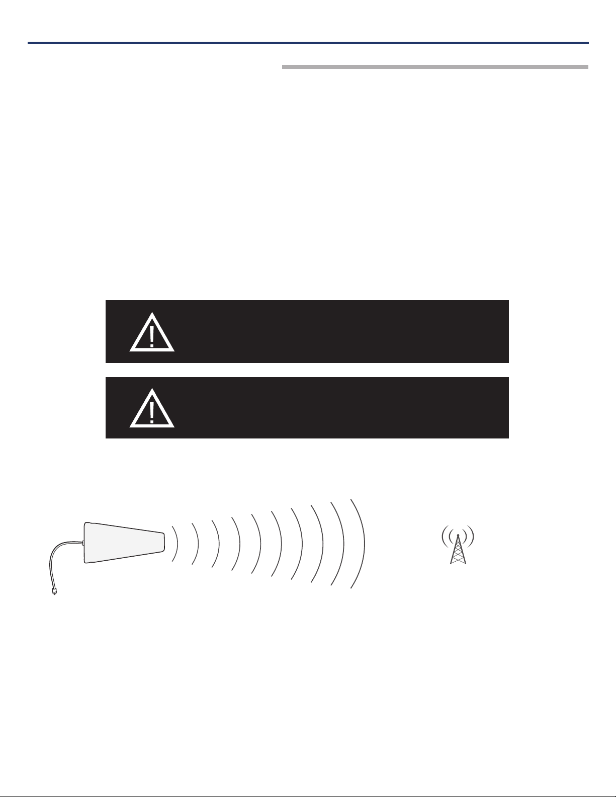
3.2 Exterior Antenna Overview
The Yagi antenna receives and transmits signals over a focused area. It must be aimed directly (line of sight) toward the radio tower that provides the strongest
signal to the building. The exterior antenna and mast (if any) must be mounted in a location that meets all of the following criteria:
• Best signal strength.
• Not co-located with other antennas or used in conjunction with other antennas.
• Away from all power lines.
• At least 6 ft. from lightning rod antennas.
• At least 32 in. from any person.
These distances are general guidelines only. Refer to the applicable building and electrical codes in your area to determine specific local requirements.
Planning the Installation

GUARDIANB 1/2W" • 5403795 REV A • 5/23
15
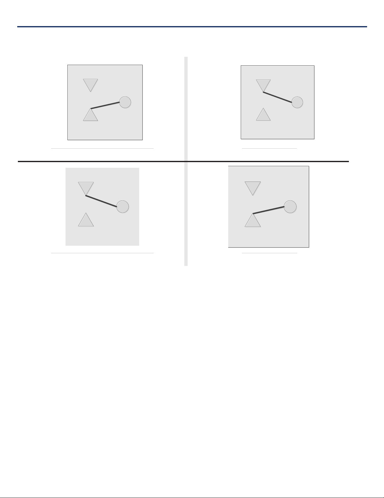
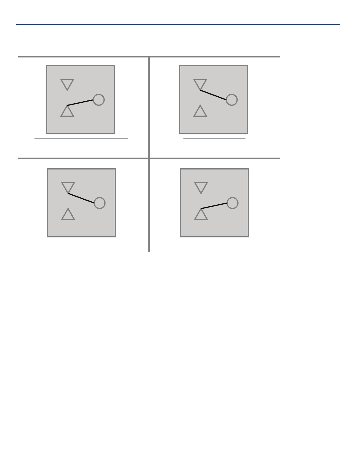
3.3 Interior Antenna Overview
You may use any combination of omnidirectional (dome) and/or directional (flat panel) interior antennas to obtain balanced signal strength throughout the
structure.
Dome antennas provide 360-degree hemispherical coverage suitable for mostly square areas, while flat panel antennas provide a focused zone of coverage
suitable for long narrow areas. The example above uses two dome antennas and one panel antenna to provide full coverage
Keep in mind that floor structures in multistory buildings can cause significant signal loss, which means that you may need to install interior antennas on more
than one floor. Here is an example of a multistory installation:
Note: You may not need antennas on every floor of a multistory building, depending on factors such as building material, BDA gain, etc.
Planning the Installation

GUARDIANB 1/2W" • 5403795 REV A • 5/23
16
3.4 Antenna Separation
Proper antenna separation prevents signal oscillation (feedback) that can interfere with the radio tower. Separation is measured in a straight line from the
exterior antenna to the closest interior antenna. The closest allowable distance depends on a number of factors, such as BDA gain level, building material, etc.
Recommended separation distances are:
Amplifier gain Min. separation (ad)
40 dB 5’-6’
45 dB 15’-20’
50 dB 50’
55 dB 60’
65 dB 75-80’
70 dB 100’
75 dB 100’-120’
80 dB 120’-180’
Vertical separation is more important than horizontal separation. If you are unable to obtain the required separation horizontally, try raising the exterior antenna.
You may also try reducing the BDA gain as described in Chapter 5 of this manual.
Antenna Safety Precautions:
You can mix and match dome and directional antennas as needed to obtain proper coverage throughout the building or area where you need to boost the signal.
If you use a Yagi exterior antenna, you should normally aim it away from all interior antennas, regardless of separation, to prevent oscillation.
3.5 BDA Location
Select an indoor location for the BDA that meets the following criteria:
• Indoor dry
• Ambient air temperature is 25°C
• Away from tightly enclosed or overly hot spaces
• Power and warning lights are easily visible
• Shortest possible cable runs to all antennas
Planning the Installation
CAUTION: SIGNAL OSCILLATION CAN CAUSE RADIO INTERFERENCE
WITH RADIO TOWERS AND RESULT IN CIVIL AND/OR CRIMINAL
PENALTIES.
OK
Antenna Aiming
Planning the Installation
GUARDIANB 1/2W" • 5403795 REV A • 5/23
17
Planning the Installation
3.6 Accessories
The final step in the planning process is to make sure you have all of the necessary accessories to complete the installation. You will need all of the items listed in
Chapter 1 of this manual plus some or all of the following:
• Cable clips: Use these to secure the cables to interior and exterior walls/ceilings.
• Appropriately rated sealant/caulking to waterproof exterior cable entry points
• Hand and/or power tools as needed to complete the installation
• Personal Equipment (PPE): Use all PPE required by local codes and/or best practices to help ensure personal safety during installation.
Note: You may need to obtain a permit from your local building department to install the BDA and antennas. Check your local building and/or electrical codes.
3.7 Need Help?
If you need help planning your installation, contact a qualified installer, the reseller who supplied you with the BDA, or TowerIQ:
Call: 844-626-7638, 7 a.m. to 5 p.m. PST, Monday – Friday
Email: cs-guardian@tower-iq.com
CAUTION: YOU ARE RESPONSIBLE FOR ENSURING THAT THE
INSTALLATION MEETS ALL APPLICABLE CODES.
GUARDIANB 1/2W" • 5403795 REV A • 5/23
18
Installation
CHAPTER 4: INSTALLATION
4.1 Soft Installation
Perform a “soft” installation of all components to test signal coverage and oscillation before making the installation permanent. Avoid making holes or other
permanent attachments during this phase. Refer to Chapter 5 for configuration and testing instructions. Proceed with final installation once configuration and
testing are complete.
4.2 Exterior Antenna
Mount the exterior antenna in the location you selected during planning. Follow all of the instructions included with the antenna to ensure that your installation is
done properly. Here are a few reminders and essential steps:
• A Yagi antenna is mounted horizontally with drip hole facing down and aimed at the desired radio tower (line of sight).
• Mount the antenna.
• Connect a length of cable to the antenna and hand-tighten.
• Run the cable along the planned route.
• Install a properly grounded TQ-LP lightning protector.
• Seal any exterior cable entry points on building exterior with caulking or sealant.
CAUTION: AVOID AIMING A YAGI ANTENNA TOWARD ANY INTERIOR ANTENNA.
WARNING: DO NOT TOUCH ANY LIVE ELECTRICAL WIRES OR ALLOW THE
ANTENNA OR CABLING TO TOUCH ANY LIVE ELECTRICAL WIRES.
Installation
GUARDIANB 1/2W" • 5403795 REV A • 5/23
19
Installation
4.3 Interior Antennas
Mount the interior antenna(s) in the location(s) you selected when planning. Follow all instructions included with the antenna(s) to ensure the installation(s) are
done properly.
Here are a few reminders and essential steps:
• Dome antennas are mounted on the ceiling as close to the center of the desired coverage area as possible, domed (convex) side pointing down.
• Flat panel antennas should be wall-mounted as close as possible to the center of the wall, or at one end of long narrow space.
• Mount the antenna.
• Connect a length of cable to the antenna and tighten until hand-tight.
• If you are installing multiple antennas, run the cable to the splitter location and connect the cable to one of the outputs on the splitter.
• Connect another length of cable to the input side of the splitter (if used) and run this cable to the BDA location.
• It is important to keep the cable runs equal or use taps to ensure a harmonious install.
CAUTION: VERIFY THAT ALL INTERIOR ANTENNAS MEET THE SEPARATION
REQUIREMENTS DESCRIBED IN THE PREVIOUS CHAPTER, AND THAT NO
ANTENNA IS AIMED TOWARD THE EXTERIOR ANTENNA.
CAUTION: DO NOT CONNECT AN INTERIOR ANTENNA TO THE SPLITTER INPUT.
Installation
GUARDIANB 1/2W" • 5403795 REV A • 5/23
20
4.4 Mounting the BDA
Mount the GuardianB as follows:
• Verify that the selected location meets all criteria described in the previous chapter.
• Mount a 24 inch x 24 inch x 3⁄4 inch thick sheet of plywood on top of sheetrock, secured into wall studs where the Type 4 housing is to be placed. The
plywood should be flush against wall.
• Once the plywood is secure, attach the Type 4 housing to the plywood base using the screws provided. In most installations, the housing will be oriented so
the I/O ports are facing down.
• Connect the outdoor antenna cable to the signal booster connector port marked OUTSIDE and tighten the connection.
• Connect the outdoor antenna cable to the signal booster connector port marked INSIDE and tighten the connection.
CAUTION: DO NOT POWER ON THE BDA UNTIL INSTRUCTED TO DO SO.
CAUTION: NEVER POWER ON THE BDA WHEN ANY ANTENNAS ARE
DISCONNECTED AS THIS COULD DAMAGE THE BDA.
Installation
CHAPTER 5: CONFIGURATION & TESTING
5.1 Powering on the BDA
1. Make sure the exterior and interior antenna cables are firmly connected to their corresponding ports on the Type enclosure.
2. Verify that the green Power light is illuminated.
3. When the booster is turned on, the band lights will flash red and green for approximately 2 seconds.
CAUTION: ONLY USE THE POWER SUPPLY INCLUDED WITH THE BDA. USE
OF ANOTHER POWER SUPPLY COULD DAMAGE THE BDA AND/OR POWER
SUPPLY.
CAUTION: DO NOT PROCEED BEYOND THIS POINT UNTIL THE BDA IS
POWERED ON AND NO RED WARNING LIGHTS ARE ILLUMINATED.
Configuration and Testing
This manual suits for next models
1
Table of contents


