Toyo LA-1041 User manual

LOAD CELL AMPLIFIER BOARD
MODEL LA-1041
OPERATION MANUAL
TOYO SOKKI CO.,LTD.
Head office: 964-24 Nippa-chou, Kouhoku-ku, Yokohama, 223-0057 Japan
TEL +81-45-540-8353
FAX +81-45-544-8354
MA4-00296-R0 (2020/11)

MA4-00296-R0
- 2 -
-- Table of contents -- Page
§1. Summary ........................................................................................ 3
§2. Appearance and Each name ................................................................. 3
§3. Operation ........................................................................................ 4
3-1) SOLDERING JUMPER FOR SETTING EXCITATION VOLTAGE TO LOAD CELL,JP2,3 ................... 4
3-2) SOLDERING JUMPER FOR SETTING AMPLIFICATION RANGE,JP1 ...................................... 4
3-3) SOLDERING JUMPER FOR SETTING A CUT OFF FREQUENCY OF FILTER,JP4,5 ....................... 4
3-4) ZERO ADJUSTMENT TRIMMER ........................................................................... 5
3-5) SPAN ADJUSTMENT TRIMMER ........................................................................... 5
3-6) RT (ADDITIONAL RESISTOR FOR INITIAL TARE SUBTRACTION) ...................................... 5
3-7) RZ (ADDITIONAL RESISTOR TO OFFSET THE OUTPUT VOLTAGE) ..................................... 5
§4. Calibration....................................................................................... 6
4-1) CALIBRATION METHOD WITH ACTUAL LOAD ............................................................ 6
§5. Troubleshooting ................................................................................ 6
5-1) BASIC CHECK POINT ..................................................................................... 6
5-2) WHAT TO DO IF THE DESIRED CALIBRATION IS NOT ACHIEVED ....................................... 6
5-3) JUDGEMENT WHETHER THIS UNIT IS MALFUNCTION ................................................... 7
5-4) CHECK LOAD CELL ....................................................................................... 7
§6. Installation and connection method ....................................................... 8
6-1) INSTALLATION ENVIRONMENT,ETC. .................................................................... 8
6-2) TERMINAL CONNECTION ................................................................................. 8
6-3) HOW TO CONNECT WIRES OF CABLE DIRECTLY......................................................... 9
§7. Specifications .................................................................................. 10
7-1) POWER SUPPLY PART FOR LOAD CELL ................................................................ 10
7-2) AMPLIFIRE PART ........................................................................................ 10
7-3) GENERAL................................................................................................ 10
7-4) INCLUDED ACCESSORIES .............................................................................. 10
7-5) WARRANTY ............................................................................................. 10
§8. Dimensional Drawing ........................................................................ 11
This document is translated from MA4-00221-R4 (Japanese)
MA4-00296-R0
- 3 -
§1.Summary
This unit is a built-in board which amplifies a signal from a strain gauge transducer and can
output voltage signal 0~±5V ( maximum ±10V at specified condition).
This unit is consisted of input signal part, amplification part and power supply part for
transducers.
The power supplied voltage is DC24V and isolated from voltage output signal.
Excitation voltage to Load Cell is selected from 5V or 2.5V at jumper setting.
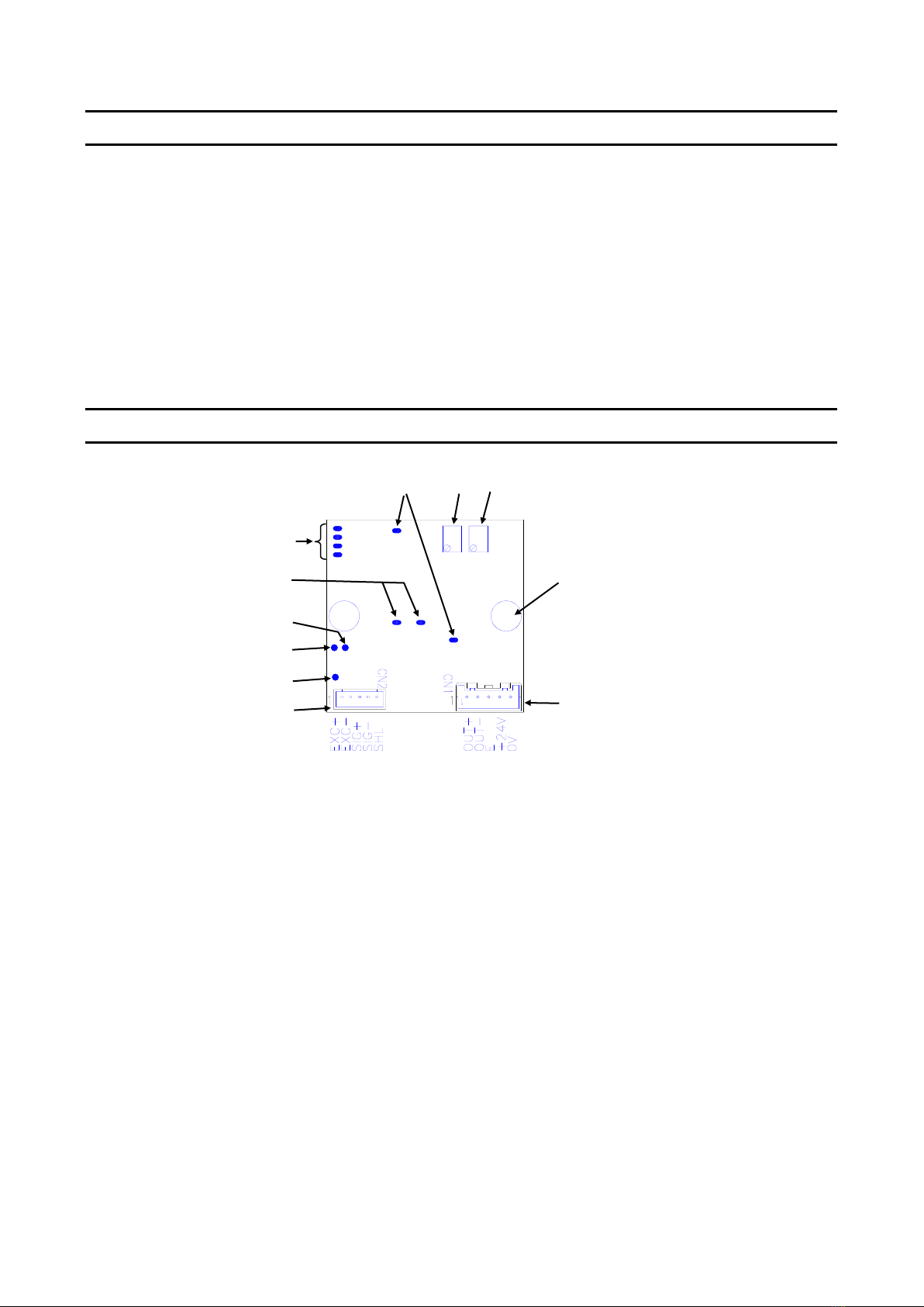
§2.Appearance and Each name
Appearance of this unit
① SPAN TRIMMER
Span adjustment trimmer (14 rotation)
② ZERO TRIMMER
Zero adjustment trimmer (14 rotation)
③ JP 1-1 to 4
Soldering jumper for setting amplification range
④ JP2, 3
Soldering jumper for setting excitation voltage to Load Cell
⑤ JP4, 5
Soldering jumper for setting a cut off frequency of filter
⑥ RT
Land for soldering additional resistor (setting Tare subtraction)
⑦ RZ
Land for soldering additional resistor (setting offset)
⑧C
Common land for soldering RT or RZ
⑨ CN1
Connector of power line and voltage output line.
There are lands on backside for soldering cables directly.
⑩ CN2
Connector of Load Cell line.
There are lands on backside for soldering cables directly.
⑪MOUNTING HOLES
Holes 2-Φ3.2 for fixing this board to the attached hexagonal
post with M3 screw
①
②
③
④
⑤
⑥
⑦
⑧
⑨
⑩
⑪
MA4-00296-R0
- 4 -
§3.Operation
This unit outputs up to ±5V. (Max.±10V depending on intensity of input signal from a sensor)
Recommend to use lead-free (Pb-free) solder because this unit is lead-free.
3-1) Soldering jumper for setting excitation voltage to Load Cell, JP2,3
Excitation voltage is 5V as standard, but 2.5V is available when soldering jumper JP2,3.
When 2.5V is set, amplification range should not be changed, but output voltage becomes
unstable slightly.
Solder jumper JP2,3 according to the following table.
Excitation voltage to
Load Cell
Setting Jumper
EXC = 5V
JP2,3: Not solder (Open)
EXC =2.5V
JP2,3: Solder (Short)
3-2) Soldering jumper for setting amplification range, JP1
By soldering an appropriate jumper, a small signal from Load Cell 0.3~2.2mV/V can be
amplified to output 0 to ±5V. JP1-2 is soldered at the time of shipment. When a input signal
is out of this range(0.7~1.2mV/V), solder jumper according to the following table.
JP 1-1, 1-2, 1-3 or 1-4 should be soldered single, not multiple.
Setting Jumper
JP1-1 to 1-4
Amplification
Span amount
to output 5V
(mV/V)
Span amount
to output 10V
(mV/V)
1-1
1-2
1-3
1-4
EXC=5V
EXC=2.5V
○
×
×
×
439~1047
878~2094
2.27~0.96
―――
×
○
×
×
730~1742
1460~3484
1.36~0.58
2.74~1.15
×
×
○
×
1065~2544
2130~5088
0.93~0.40
1.87~0.79
×
×
×
○
1752~4184
3504~8368
0.57~0.24
1.14~0.48
〇:Solder、×:Not solder
3-3) Soldering jumper for setting a cut off frequency of filter, JP4,5
When an input signal from Load Cell fluctuates due to external vibration, set a cut off
frequency of filter to be lower and make the output voltage becomes less affected from that
fluctuation.
Solder JP4,5 according to the following table
Cut off frequency
Setting Jumper
fc = 100 Hz
JP4,5: Not solder (Open)
fc = 2 Hz
JP4,5: Solder (Short)
Noise level originated from amplifier itself at fc=2Hz decreases half compared to the one at
fc=100Hz. The measured value should be more stable.
MA4-00296-R0
- 5 -
3-4) ZERO adjustment trimmer
Unbalanced voltage of Load Cell or an equivalent voltage of Tare amount can be canceled to
zero by adjusting ZERO trimmer (14 rotation).
If the output voltage cannot be adjusted to be zero, additional resistor, RT or RZ is required
to mount.
3-5) SPAN adjustment trimmer
This is a span adjustment trimmer (14 rotation) to set the output voltage to the desired level.
If the output voltage cannot be adjusted to the desired level, change the amplification range
by soldering jumper, JP1. Refer to 3-2)
3-6) RT (Additional resistor for initial Tare subtraction)
When an equivalent voltage of Tare amount is so large that the output voltage cannot be
adjusted to be zero, mount an additional resistor RT to cancel it. Output voltage decreases
toward minus.
When a resistor value of RT is small, cancellation of Tare amount is larger. Select an
appropriate resistor value according to the following table. Use a metal film resistor with
temperature coefficient 50ppm/℃or less.
Cancellation of
Tare amount
Required resistor value, RT
Load Cell 350Ωtype
Load Cell 700Ωtype
0.2mV/V
about 430kΩ
about 910kΩ
0.4mV/V
about 220kΩ
about 430kΩ
0.6mV/V
about 150kΩ
about 300kΩ
0.8mV/V
about 110kΩ
about 220kΩ
1.0mV/V
about 91kΩ
about 180kΩ
3-7) RZ (Additional resistor to offset the output voltage)
If there is an offset level of output voltage toward minus and output voltage cannot be
adjusted to be zero, mount an additional resistor RZ to increase the output voltage to
cancel the offset level. This operates as an opposite role of RT. Select an appropriate
resistor value according to the above table 3-6). Use a metal film resistor with
temperature coefficient 50ppm/℃or less.

MA4-00296-R0
- 6 -
§4.Calibration
Calibration is done by two steps. One is that set the output voltage to zero when no load
is applied. Two is that set the desired output voltage when an object is loaded, which is
operated by actual load calibration using a reference weight as an actual load.
When this unit and Load Cell are combined to ship from TOYO, calibration has been done
at our factory.
4-1) Calibration method with actual load
1). Put nothing on Load Cell (only the initial Tare load is applied).
2). Turn a ZERO trimmer to adjust the output voltage to 0V.
3). Place a weight such as a reference weight on Load Cell and turn a SPAN trimmer to
adjust the output voltage to the relevant value of the weight.
4). Remove a weight such as a reference weight from Load Cell.
5). Confirm that the output voltage is 0V. If not, repeat from step 2) above.
If calibration cannot be done properly, refer to section §5 Troubleshooting and take
measures to solve a problem.
§5.Troubleshooting
If this unit is malfunctioning, please contact us if the problem cannot be solved by the
following measures. At this time, please inform us of the model name, product serial number,
the malfunction symptoms and usage as much as possible. The model name of Load Cell or
sensor connected to this unit should be also informed.
5-1) Basic check point
1). Check whether the power supplied voltage DC24V is normal and stable
2). Check whether the terminals are connected correctly and firmly
5-2) What to do if the desired calibration is not achieved
1). Zero adjustment cannot be done.
Zero adjustment range is ±15% against rated output voltage
If the output is more than 0V even if ZERO trimmer is turned fully counterclockwise
(CCW), mount an additional resistor, RT, to decrease the output voltage.
If the output is less than 0V even if ZERO trimmer is tuned fully clockwise (CW), mount
an additional resistor, RZ, to increase the output voltage.
2). When span adjustment, the desired output voltage cannot be set.
If the output goes below the desired value even if SPAN trimmer is turned fully clockwise
(CW), solder JP-1 to increase the amplification by one step.
If the output exceeds the desired value even if SPAN trimmer is turned fully
counterclockwise (CCW), solder JP-1 to decrease the amplification by one step.
4 steps can be set according to JP-1 jumper setting. If the desired output is not obtained
even if all the JP-1 jumper setting has been done, check whether Load Cell output satisfies
the sensitivity adjustment range of this unit.
The sensitivity adjustment range of this unit is -2.2mV/V to 2.2mV/V.

MA4-00296-R0
- 7 -
Signal from Load Cell, 0.3 to 2.2mV/V is required to output 0 to 5V. Output 10V is possible
when a signal from Load Cell is more than 0.6mV/V
3). Output voltage is out of range of ±5V even though it is not overloaded.
①When a part of Load Cell cable is disconnected. (Refer: Section 5-4)
②Additional resistor RT, RZ is inappropriate. (Refer: Section 3-6)
③When Load Cell becomes defective. (Refer: Section 5-4)
5-3) Judgement whether this unit is malfunction
1). Check the excitation voltage of Load Cell
Check whether the excitation voltage between #1 (+EXC) and #2 (−EXC) of CN2 is stable
at 5V±0.25V (2.5V±0.13V). If it is not stable, a power supply circuit inside this unit may
be defective.
2). Short the output voltage of Load Cell (making an electric short between terminal #3
(+SIG) and #4 (−SIG)). In other words, the input voltage to this unit is made zero.
In this state, the voltage which adjusted by ZERO trimmer is output, so the output does
not become 0V, but it can be checked whether the output is stable.
If it is not stable, an amplification circuit in this unit may be defective. If it is stable, check
Load Cell side.
5-4) Check Load Cell
Since Load Cell is composed of a bridge circuit, it is possible to make a rough judgement
by measuring the input / output resistance and insulation resistance.
*Please be sure to turn power OFF of this unit before checking Load Cell.
1). Failure judgement method by Load Cell resistance value.
①Remove all Load Cell cables.
②Measure the bridge resistance of Load Cell with a tester and check if there is any
abnormality in the input / output resistance.
2). Failure judgement method based on Load Cell insulation resistance
①Remove all Load Cell cables.
②Measure the insulation resistance between shield and each cable of Load Cell at a
voltage within 50V.
In addition, the insulation resistance between a metal case of Load Cell and each cable
other than shield is also measured at a voltage within 50V.
③If the insulation resistance is 1000MΩ or more, Load Cell is mostly good

MA4-00296-R0
- 8 -
§6.Installation and connection method
6-1) Installation environment, etc.
1) The operating temperature range of this board is 0 ℃ to 40℃.
Consider installing in a place not exposed to the direct sunlight.
2) This board is operated with power supplied voltage DC24V±10%.
Note that connecting to a different voltage may cause failure or damage.
3) Fix this board with holes 2-Φ3.2 using attached hexagonal posts or M3 screw
6-2) Terminal connection
The shield line of each cable shall be grounded by either this unit or each connected
instrument, so that there is no ground loop.
1). Power line and output voltage cable connection (CN1)
Connector: B05B-XASK-1 (JST)
No.
Connection signal
1
OUT+
Output voltage (+)
2
OUT-
Output voltage (-)
3
E
Grounding (Earth)
4
+24V
Power supplied voltage (DC+24V)
5
0V
Power supplied voltage (DC0V)
※#3(E) is connected to one of the fixing holes 2-Φ3.2 inside
※Signal between #2(OUT-) and #5(0V) is isolated. Make them apart when wiring.
※When wiring a cable of output voltage, use a shielded cable and terminate a shield at
the connected unit side.
2). Load Cell cable connection (CN2)
Connector: B5B-PH-K-S (JST)
No.
Connection signal
1
EXC+
Excitation voltage to Load Cell (+)
2
EXC-
Excitation voltage to Load Cell (-)
3
SIG+
Input signal from Load Cell (+)
4
SIG-
Input signal from Load Cell (-)
5
SHL
Shield line of Load Cell cable
※There are lands on backside of this board to solder each wires of cable directly, instead of
use of connector CN1 and CN2

MA4-00296-R0
- 9 -
6-3) How to connect wires of cable directly
V
DC24
V
Wiring as short
as possible
Backside of a board
Load Cell
Shield of this cable should be
grounded at connected unit side
Solder here

MA4-00296-R0
- 10 -
§7.Specifications
7-1) Power supply part for Load Cell
1). Excitation Voltage DC5V±5%as standard
DC2.5V±5%is available when soldering jumper, JP2,3
2). Output current 22mA maximum
able to connect one Load Cell 350Ωtype when EXC=5V,
one Load Cell 350Ω/120Ωtype when EXC=2.5V.
7-2) Amplifire part
1). Zero adjustment Range ±15% against rated output voltage, Max. 5V
Multi-turn trimmer adjustment, 14 rotations
2). Sensitivity Span of input voltage 0.3 to 2.2mV/V can output 0 to 5V
adjustment by 14 rotations trimmer and soldering jumper of range, JP1
RANGE-1: 1.1 to 2.2mV/V
RANGE-2: 0.7 to 1.2mV/V (at the time of shipment)
RANGE-3: 0.45 to 0.8mV/V
RANGE-4: 0.3 to 0.5mV/V
Standard sensitivity : Output 0 to 5V when EXC=5V,
0 to 1mV/V input, Gain=1000
3). Output signal 0 to 5V voltage signal, (Load resistance 2kΩor more)
For span of 0.6mV/V or more, output of 0 to +10V is possible.
4). Non linearity ±0.1%FS
5). Cut-off frequency approx. 100Hz (-3dB)
2Hz (-3dB) is available when soldering jumper, JP4,5
6). Temperature coefficient
Zero ±0.01%FS/℃typ. (standard sensitivity)
(twice the above at EXC=2.5V)
Sensitivity ±0.01%FS/℃typ.
7-3) General
1).Power stability ±0.05%FS (Power supplied voltage fluctuation within±10%)
2).Power supplied voltage DC24V±10%
3).Current consumption 100mA typ.
4).Operating Temp./Humidity 0~+40℃、20~85%R.H. (without condensation)
5).Mass approx. 30g
6).Mounting method Fix by using holes 2-Φ3.2 of this board
7-4) Included Accessories
1). Cable with connector for connecting power line and output line 1 pc
2). Cable with connector for connecting Load Cell 1 pc
3). Operation Manual 1 copy
7-5) Warranty
This board is covered by one year warranty against TOYO’s manufacturing or design fault.
(The board is taken over and repaired)
MA4-00296-R0
- 11 -
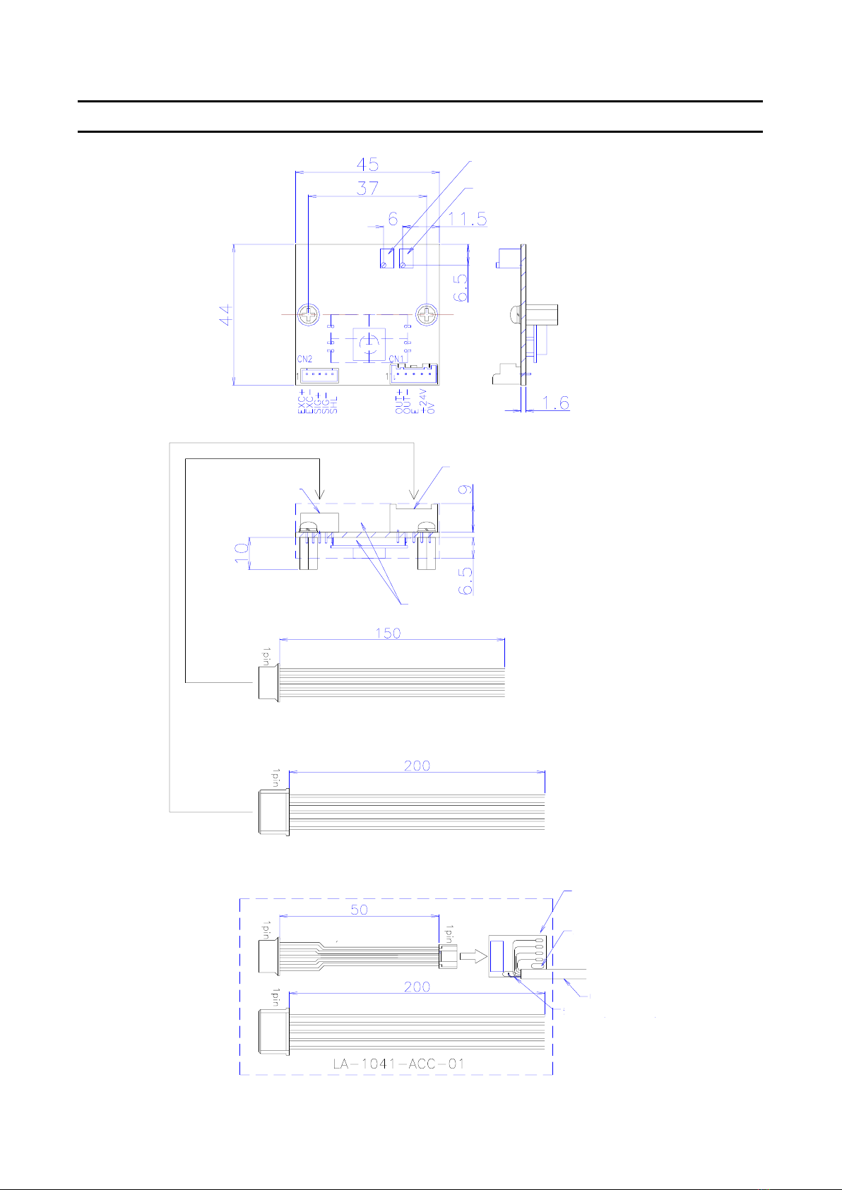
§8.Dimensional Drawing
Zero adjustment trimmer
Span adjustment trimmer
Connector of power line
and voltage output line
Connector of
Load Cell line
Parts mounting area
PH connector
(2mm pitch)
Recommend to use a shielded cable
when extending
XA connector
(2.5mm pitch)
Cable with connector
Connector of Load Cell
Connector of power line and output
(Option)
Board of converting
cable
S o l d e r p a d
Hole of binding band
Load Cell cable
Shield of cable (solder)
Table of contents
Other Toyo Amplifier manuals


