TOYODenki VFDB2009 Series User manual

VFDB2009
Operation Manual

1
Forword
Thank you for choosing Toyo VFDB2009 series dynamic brake unit.
This instruction manual contains information regarding the VFDB2009 series dinamic brake unit. For
correct use, please carefully read this instruction manual prior to using the VFDB2009 series dynamic brake
unit.
In order to accommodate the many special functions to a wide variety of applications in addition to the
inverter functions, please thoroughly read the VF66B inverter manual as well as any other applicable
specialized instruction manuals.
2
Please read before use
For safety
Before installing, operating, maintaining and inspecting VFDB2009 series dynamic brake unit, please read
this manual and all other appendices thoroughly in order to get familiarize with the feature of this option,
safely information and correct handling. In this instruction manual, the safety instructions are classified in to
two levels: DANGER and CAUTION. These signs have important instructions. Please follow the instructions
without fail.
DANGER
Indicates a hazardous situation which may result in death or serious injury if it
is handled improperly.
CAUTION
Indicates a hazardous situation which may result in moderate or minor injury or
only in property damage if it is handled improperly. However, such a situation
may lead to serious consequences depending on circumstances.
CAUTION [Installation]
Mount on the noninflammable material as metal, etc.
Doing so may cause a fire.
Do not place any flammable materials near the DB unit.
Doing so may cause a fire.
DB unit is an open structure, it is put into panel and it is carried out as a turning-on-electricity part.
Failure to do so may cause an electric shock.
Do not carry with the option cover.
Doing so may lead to personal injury by dropping.
Install the DB unit at endurable place ageinst weight.
Doing so may lead to personal injury by dropping.
Do not install or operate the DB unit if it is damaged or has any of its parts missing.
Doing so may lead to personal injury.
DANGER [Wiring]
Before wiring, make sure the power is OFF.
Failure to do so may cause an electric shock or fire.
Make sure that the unit is correctly earthed.
Failure to do so may cause an electric shock or fire.
Wiring must be done by skilled technicians.
Failure to do so may cause an electric shock or fire.
Wire the unit after it is installed.
Failure to do so may lead to personal injury or cause a fire.
CAUTION [Wiring]
Please check that the voltage setting change of DB unit is in agreement with inverter power supply voltage.
5.2.1 Change of a power supply voltageand5.4.3 F20Power supply voltage selection ・Master /
slave selection ・Station number set-up mode are reffer to.
Failure to do so may cause an electric shock or fire.

3
DANGER [Operation]
Turn the power ON after close the panel door. Do not open the panel door while the power is ON.
Doing so may cause an electric shock.
Do not operate any switch with wet hands.
Doing so may cause an electric shock.
Do not touch the DB unit while the power is ON, even if the DB unit is in the idle state.
Doing so may cause an electric shock.
CAUTION [Operation]
The DB unit radiating fin, the radiating resistors and Dynamic brake resistors are hot. Do not touch them.
Failure to follow this warning may cause burns.
DANGER [Maintenance, inspection and parts replacement]
Always turn the power OFF before inspecting the DB unit and passing of 10 minutes or more from
confirmation of stop of motor. Also check DC voltage between P to N and confirm that it is less than 30V.
Failure to do so may cause an electric shock, personal injury or fire.
Unauthorized persons shall not perform maintenance, inspection or parts replacement.
Use insulated tools for maintenance and inspection.
Failure to do so may cause electric shock or personal injury.
DANGER [Other]
Never modify the unit.
Doing so may cause electric shock or personal injury.
CAUTION [General precautions]
Some illustrations given in this manual show the in DB unit from which the option cover or safety shields have
been removed to illustrate the details. Before operating, reinstall these covers and shields to their original
positions and the DB unit according to this manual.
These safety precautions and specifications stated in this manual are subject to change without notice.

4
Table of contents
PLEASE READ BEFORE USE ...................................................................................................................................................2
FOR SAFETY......................................................................................................................................................................................... 2
CHAPTER 1 FUNCTIONAL OUTLINE ...............................................................................................................................6
1.1 OPERATION PRINCIPLE .............................................................................................................................................................. 6
CHAPTER 2 BASIC SPECIFICATION..................................................................................................................................8
2.1 COMMON SPECIFICATION ...................................................................................................................................................... 8
2.2 UNIT SPECIFICATION............................................................................................................................................................... 8
CHAPTER 3 INSTALLATION AND WIRING...................................................................................................................9
3.1 INSTALLATION.......................................................................................................................................................................... 9
3.2 CONNECTION......................................................................................................................................................................... 10
3.3 TERMINAL SPECIFICATIONS........................................................................................................................................................ 13
CHAPTER 4 OUTLINE DIMENSION................................................................................................................................ 14
CHAPTER 5 OPERATION.................................................................................................................................................. 15
5.1 EXPLANATION OF OPERATION .................................................................................................................................................. 15
5.1.1 VFDB2009-Z printed circuit board .......................................................................................................................... 15
5.1.2 Display............................................................................................................................................................................. 17
5.1.3 Operation method of a display for indication...................................................................................................... 17
5.2 SET-UP BEFORE OPERATION...................................................................................................................................................... 19
5.2.2 Set-up of single operation or Master/Slave system paralle operation.......................................................... 21
5.3 DYNAMIC BRAKE OPERATION................................................................................................................................................... 22
5.4 SET-UP ITEMS ........................................................................................................................................................................... 23
5.4.1 List of set-up items...................................................................................................................................................... 23
5.4.2 F10Setting mode of DB operation voltage.................................................................................................... 23
5.4.3 F20Power supply voltage selection ・Master / Slave selection ・Station number set-up mode24
5.4.4 F30The display gain / offset automatic adjustment mode of D.C. voltage........................................ 26
5.4.5 F40The display gain / offset hand adjustment mode of D.C. voltage................................................. 27
CHAPTER 6 SELECTION OF PERIPHERAL DEVICE.................................................................................................... 29
6.1 RESTRICTION IN DB OPERATION .............................................................................................................................................. 29
6.1.1 DB operating time and a quiescent period........................................................................................................... 29
6.1.2 Current value which the transistor built in DBunit permits.............................................................................. 29
6.2 SELECTION OF BRAKING RESISTOR ............................................................................................................................................ 30
6.3 SELECTION OF THERMAL RELAY................................................................................................................................................ 33
6.4 EXAMPLE OF PERIPHERAL EQUIPMENT SELECTION...................................................................................................................... 33
CHAPTER 7 OPTION ....................................................................................................................................................... 34

5
7.1 COMMUNICATION OPTION BOARD [DBIF2009-Z PC BOARD]......................................................................................... 34
7.1.1 Extension of the function by appling of a communication option PC board ............................................. 34
7.1.2 Communication option DBIF2009-Z PC board.................................................................................................... 35
7.1.3 Attachment of a communication option board, connection of a connector .............................................. 36
7.1.4 Connection of a telecommunication cable and a setup of a terminator switch........................................ 38
7.1.5 Station number set-up................................................................................................................................................ 43
7.1.6 Main circuit wiring at the time of communication option PC board attachment...................................... 43
7.1.7 Set-up of the inverter at the time of communication option PC board use................................................ 45
7.2 OPTION COVER........................................................................................................................................................................ 45
CHAPTER 8 REPLACEMENT WITH THE OLD MODEL DB UNIT ........................................................................................... 46
8.1 REPLACEMENT WITH VFDB2002 SERIES.................................................................................................................................46
8.2 REPLACEMENT WITH VFDB5022,VFDB5044,VFDB91-200............................................................................................. 46
8.3 PARALLEL OPERATON METHOD WITH VFDB SERIES.................................................................................................................. 47
8.3.1 Setup of VFDB2009 series......................................................................................................................................... 47
8.3.2 Connection..................................................................................................................................................................... 47
CHAPTER 9 TROUBLE SHOOTING .............................................................................................................................. 49
9.1 PROTECT DISPLAY.................................................................................................................................................................... 49
9.2 TROUBLE SHOOTING................................................................................................................................................................ 49
9.3 RESET ...................................................................................................................................................................................... 50
9.4 PROTECTION OAT THE TIME OF COMMUNICATION OPTION USE................................................................................................ 51
CHAPTER 10 MAINTENANCE ....................................................................................................................................... 52
10.1 REGULAR CHECK ................................................................................................................................................................... 52
10.2 DISPOSAL.............................................................................................................................................................................. 52

6
Chapter 1 Functional outline
VFDB2009 series dynamic brake system is equipment (DB unit) which controls the regeneration energy for
acquiring brake power. In order to acquire brake power other than DB unit, the braking resistor (DBR) which
consumes regeneration energy as heat, and the protection thermal relay (OCRY) which carries out electrical
overload detection are required.
The brake power gained due to the loss (a total of about 10 to 15%) by inside the inverter and inside the
motor because the inverter unit doesn’t have the ability to process the suppresion energy. When making the
continuous regeneration energy under operation, or the big regeneration energy in a sudden slowdown
consume by resistance and acquiring brake power, VFDB2009 series dynamic brake system is used.
VFDB2009 series dinamic brake system has compatibility in VFDB2002 series dynamic brake system,
attachment, and an operating method. The VFDB2002 series dynamic brake system applied to the present
system is exchanged for a VFDB2009 series dynamic brake system, and a simple substance and operation to
mix are possible.
VFDB2009 dinamic brake system is designed so that the content of a lead, mercury, cadmium, sexavalent
chrome, PBB, and PBDE may be based on the RoHS instructions which EU defines in consideration of the
influence on environment.
1.1 Operation principle
The suppression energy returns to the inverter unit when motor becomes the regeneration mode. The DC voltage of
inverter rises, because the inverter doesn't provide the regenerative function to the power supply. The DB unit detects this
DC voltage, operates the switching element (IGBT) in the unit, and consumes the regenarative energy to resistor (DBR)
for power generation. If the regenerative mode became finish,DC voltage returns to a normal value, switching element
(IGBT) becomes an immovable work.
* Regenerative mode *
The case where the torque has been put out the motor to the machine`s called powering mode in the place where the
machine is driven with inverter. The motor rotation frequency rises more than the output frequency of the inverter, it enters
the state to have returned the torque from the machine to the motor under such a condition when the sudden
deceleration or a big load of GD2is naturally decelerated from this state for instance, this is called the regentive mode.
DB UNIT
Figure 1-1 basic circuit
INVERTER
UNIT
DBR
OCRY
DC/DC
IGBT

7
VDC
Input Output
Motor
VDC
Input Output
Motor
Fig1-2 Power flow of powering mode Fig 1-3 Power flow of regenerative mode
CAUTION [Safety precautions]
Carefully read the instruction manual before use, and use the inverter correctly.
Our VFDB2009 series dynamic brake system are not designed or manufactured for the purpose of use in
life-support machines or systems.
If you intend to use the product stated in this document for special purposes, such as passenger cars, medical
devices, aerospace devices, nuclear energy controls and submarine relaying machines or systems, consult our
sales department.
This product is manufactured under strict quality control. However, if it is used in critical equipment in which
VFDB2009 series dynamic brake system failure may result in death or serious damage, provide safeguard to
avoid serious accidents.
To use this product, electrical work is necessary. The electrical work must be done by qualified expert.

8
Chapter 2 Basic Specification
2.1 Common specification
The common specification of VFDB2009 series dinamic brake system (VFDB2009 series DB unit) are shown
in the following table.
Table 2.1 Common specification
DB operation
voltage
(Adustment)
[200V series]DC300V~400V±3%
[400V series]DC600V~800V±3%
Parallel operation
MasterSlave sysytem
Maximum
parallel number
Six sets
Protection
function
Abnormalities of a main circuitFin overhaetAbnormalities of a preset value
200V series over voltage
Correspondence
standard
RoHS instruction conformity
Environmental condition
Temperature
of operation
0~50℃
Preservation
temperature
-20~60℃
Humidity
20~90%Not condensation
Altitude
1000m or less
Atmosphere
No poisonous gas, metal powder, and oil and fat etc.
Protection
structure
IP00JIS C 0920EN/IEC60529
Structure of an open type where the protection to a human body, the protection to
invasion of a solid object, and the protection to invasion of water are not taken into
consideration in particular.
2.2 Unit specification
The specification of each VFDB2009 series DB unit is shown in the following table.
Table 2.2 DB unit specification
Type
VFDB2009-50
VFDB2009-200N
VFDB2009-200F
Rated
current
Peak
current
※1
50[A]1[min]
200A[] 1[min]
200[A] 1[min]
Continuous
current
12[A]
58[A]
120[A]
Cooling sysytem
Air cooling without blower
Air cooling without blower
Air cooling
※1:DB usage rate =10[%]
9
Chapter 3 Installation and Wiring
3.1 Installation
○
1Installation location of unit
The conditions in the installation location affect the life and the reliability of the inverter. Avoid using it in the
following places.
(1) If the DB unit is installed in a highly humid or dusty place, or in a place exposed to water or oil, the
circuit insulation will be deteriorated, and the life of the parts will be shortened.
(2) If the working ambient temperature is too high, the life of the capacitor and cooling fan motor will be
shortened.
(3) In a place with corrosive gas, connector contact failure, breaking of electric wires and damage of parts
may be caused.
(4) In a place with heavy vibration, connector contact failure, breaking of electric wires and damage of parts
may be caused.
(5) If the DB unit is used at an ambient temperature of 0℃or less, use a heater to increase the temperature
to more than 0℃at the start of the DB unit. After the DB unit starts, it generates heat by itself to
more than 0℃and will operate normally.
Installing the unit
To use dynamic brake unit installed in a control panel, install as follows.
DANGER [Mounting]
Improper installation may cause an electric shock or a fire.
(1) Installation direction
VFDB2009 DB unit turns a main circuit terminal down and attaches it perpendicularly. If installed
horizontally, it will not be ventilated sufficiently and will be overheated. Enogh consideration must be
taken to the routes of suction and exhaust of air.
Moreover, the cooling fan of DB unit (VFDB2009-200F) with a cooling fan inhales from the bottom, and
exhausts air to the top. Keep sufficient space above the unit so that ventilation is not prevented by
wiring dusts, etc.
When installing VFDB2009 DB unit, keep cooling spaces as shown in the following figure3.1.
When VFDB2009 DB unit is installed in a control panel, ventilate the panel to keep the temperature in
the panel within 50℃.If the ambient temperature is high, the reliability of the inverter will be
degraded.
(2) Cautions
Surely exhaust the heat generated by the DB unit to the outside of the panel. Prevent the exhaust from
the DB unit to circulate in the panel.
Install the resistor on the outside of the panel as much as possible.
Avoid using the DB unit in a considerably coarse environment.

10
Min100
[mm]
Min100
[mm]
Figure 3.1 DB unit cooling space
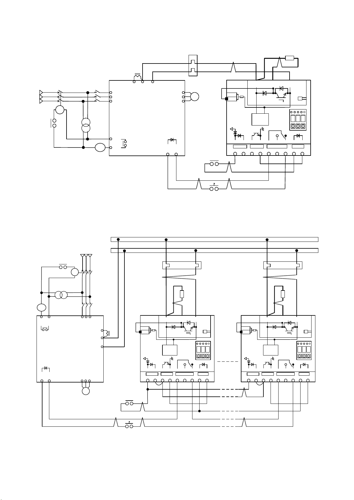
3.2 Connection
A maximum of six sets of parallel runs are possible for VFDB2009 series dynamic brake system. Please
keep in mind that control wiring differs in single operation and parallel operation. Moreover, it is necessary
to change a setup of DB unit in accordance with wiring. refer to "5.2.2 Set-up of single operation or
Master/Slave system paralle operation" for change of a setup. In addition, a parallel operation with
VFDB2002 series is also possible for this VFDB2009 series. Refer to "8.3.2 connection method" for the wiring
at the time of a parallel run with VFDB2002 series.
The parallel operation of DB unit of our company has adopted “Master & Slave system.” “Master & Slave
system” sets to Master DB unit which each DB unit performed DB operation detection and carried out DB
operation detection previously, and takes out instructions of ON/OFF of switching device (IGBT) to other
parallel units. Figure 3.3 shows the connection method and the wiring between each DB unit becomes the
same.
DB unit set up by Master unit performs DB operation detection, and "Master & Slave system" of VFDB2002
series takes out instructions of ON-OFF of switching device (IGBT) of a slave unit. Even when VFDB2009
series DBunit is applied, "Master & Slave system" of VFDB2002 series is possible. Refer to Figure 8.1 for the
connection method in that case.
In accordance with the power supply voltage system of an inverter, a DB unit setup is required before use.
When DB unit is used by mistaken setup, there is fear of breakage and unusual operation. Refer to "5.2.1.
Change of a power supply voltage" and "5.4.3 F20 (Power supply voltage selection and Master/Slave
selection and Station number set-up mode) for a setup of a power supply voltage system.
11
1 2 3 4 5 6 8 97
P PR N
OCRY
DBR
CN2
CN3
400V
200V
TH
52MAX
8 8 8
SHT
OCRY
52MAX
M
TB2
DB
_IN DB_ON 86A 52MA
MCCB MC
R
S
T
12
U
V
W
DCL
RUNNING SIGNAL
INVERTER UNIT
Inverter Operation
Contact (52MA)
400V Line
at
400V/200V
Transfomer
DB Unit
DB Voltage
DC/DC
Converter
Slave Master Protection DB Operation
Inverter Operation command
Figure 3.2 Example of connection of single operation
52MAX
M
U VW
SHT
OCRY
MCCB
MC
R S T
52MAX
1
2
1 2 3 4 5 6 8 97
P PR N
OCRY
DBR
CN2
CN3
400V
200V
TH
8 8 8
TB2
DB
_IN DB_ON 86A 52MA
1 2 3 4 5 6 8 97
P PR N
OCRY
DBR
CN2
CN3
400V
200V
TH
8 8 8
TB2
DB
_IN DB_ON 86A 52MA
DC
L
400V Line
at
400V/200V
Transfomer
Inverter Operation
Contact (52MA)
INVERTER UNIT
RUNNING SIGNAL
Inverter Operation command
D.C. Busbar
DB Unit
DB Voltage
DC/DC
Converter
Slave Master Protection DB Operation
DB Unit
DB Voltage
DC/DC
Converter
Slave Master Protection DB Operation
6parallels
or less
Figure 3.2 Example of connection of parallel operation

12
○Notes at the time of wiring
Lay the main circuit wires and the control signal wires apart from each other.
Wiring of an inverter should follow the instructions manual of inverter each model.
Inside of a figure 3 of a part of the connection example wires for the twist. Please lay out the
equipment to shorten as much as possible and wire for wiring. If the twist line is not used, the surge
voltage is by the twice or more. there is a possibility of damaging the unit.
Please connect input power source (P,N) of DB unit from the middle D.C. power (+2,-) of the Inverter
unit by twist cable. Refer to Table 3-1 for the size of the use cable and number of time to twist .
Change the connector on DB unit according to the voltage system of an inverter. Refer to "5.2.1
Change of power supply voltage" for details.
Wire the DB unit for the interlock relay use doing that operates by the INV RUN signal contact
(52MAX) of the inverter so that the DB unit should not work while the inverter is stopping and wire
use twist cable. The interlock relay must use the lopower relay.
Select braking resistor (DBR) so that required regeneration power is obtained, and take protection
coordination in thermal relay (OCRY). It becomes a cause of a fire when cooperation cannot be taken.
About selection of braking resistor (DBR) and thermal relay (OCRY), refer to "6.2 Selection of braking
resistor" and "6.3 Selection of thermal relay." Thermal relay (OCRY) should use what operates with
direct-current current.
Please shorten wiring to braking resistor (DBR) and thermal relay (OCRY) as much as possible, and
twist it, and the wiring near braking resistor (DBR) should perform heat-resistant processing.
Since braking resistor (DBR) generates heat (200 degrees or more), it is installed in a place with
sufficient ventilation, and does not put combustibles on the surroundings.
By operation of thermal relay (OCRY), the trip of circuit braker (MCCB) or electromagnetic contactor
(MC) by on the inverter input is carried out.
Protection contact(86A) of the DB unit operates by protection of DBunit. Please connect the
protection contact (86A) of the DB unit to the circuit of inverter operation instructions in series as an
interlock of inverter operation.
Main circuit wiring of an inverter and DB unit should set to a maximum of 10m, and please wire as
short as possible.
Please be sure to connect the ground of a DB unit.
When you use DB unit by a parallel operation, please be sure to connect master instructions signal
(DB-IN) and a slave input signal (DB-ON).
13
Table 3.1 Main circuit used cable (DB usage rate 10%ED
Main current[A]
Wiring size[mm2]
Number of times to twist[turn/m]
200
38
5
160
22
7
110
14
8
80
8
10
50
8
10
40
5.5
10
30
3.5
10
18
2
10
※Table 3.1 is the wire size at the time of adopting the fire-resistant poly flex time electric wire.
( Example:MLFC[Hitachi Cable])
※Twist a wire equally so that the length of each wire becomes the same.
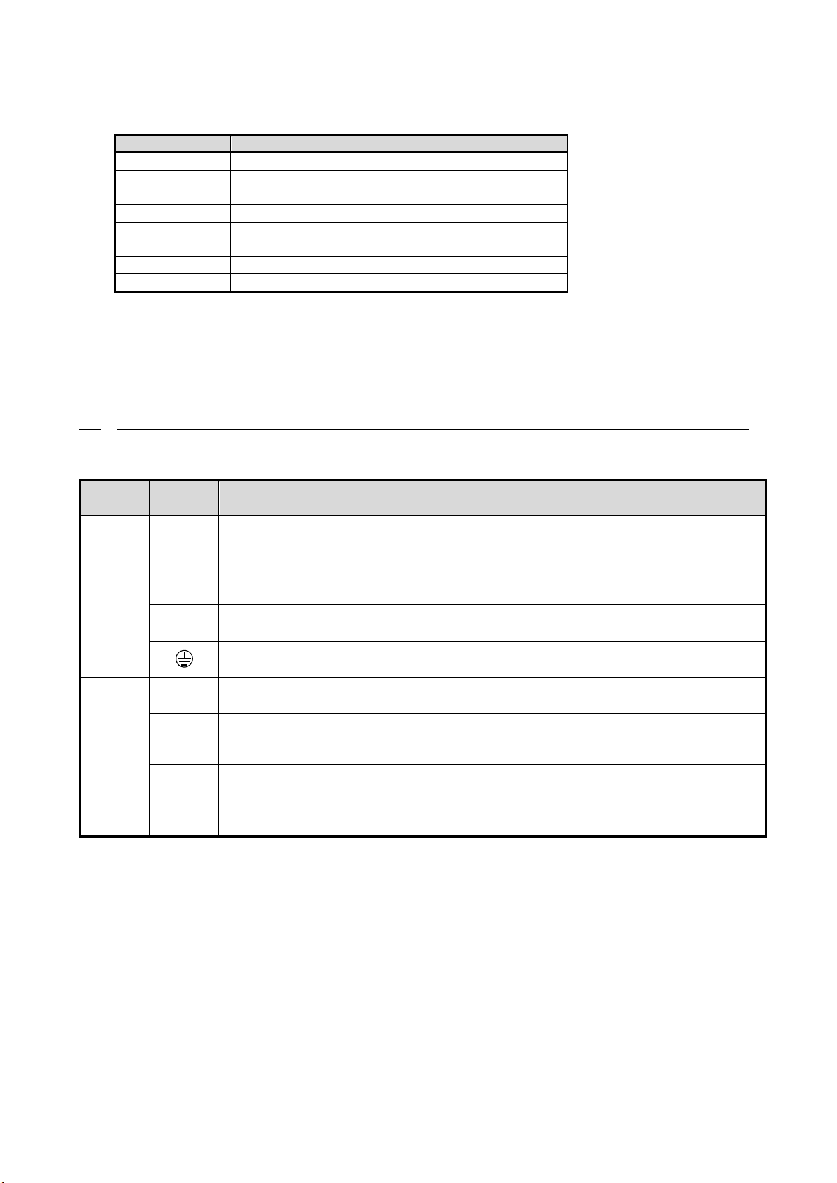
3.3 Terminal specifications
Table 3.2 List of terminal specification
Device
Terminal
number
Use
Description
Main
circuit
P
DC voltage input (+ side)
For DBR connection
For thermal relay (OCRY) connection
Connect the inverter-middle D.C. voltage(○
2)
Connect a braking resistor
Connect the thermal relay(OCRY)
PR
For DBR connection
Connect a braking resistor
N
DC voltage input (- side)
For thermal relay (OCRY) connection
Connect the inverter-middle D.C. voltage(○
)
Connect the thermal relay(OCRY)
Earth
Connect the ground
VFDB
2009-Z
terminal
block
TB2
DB-IN
Slave input
DB operation will be started if a signal is
inputted during DB operation permission.
DB-ON
master instructions
A signal is outputted when the
inverter-middle D.C. voltage exceeds DB
operation starting potential (F10).
86A
Protection contact
DB unit turns on during the protection mode.
(86A:AC230V 0.5A)
52MA
Operation contact
It will be in the state in which DB operation is
possible by ON.
14
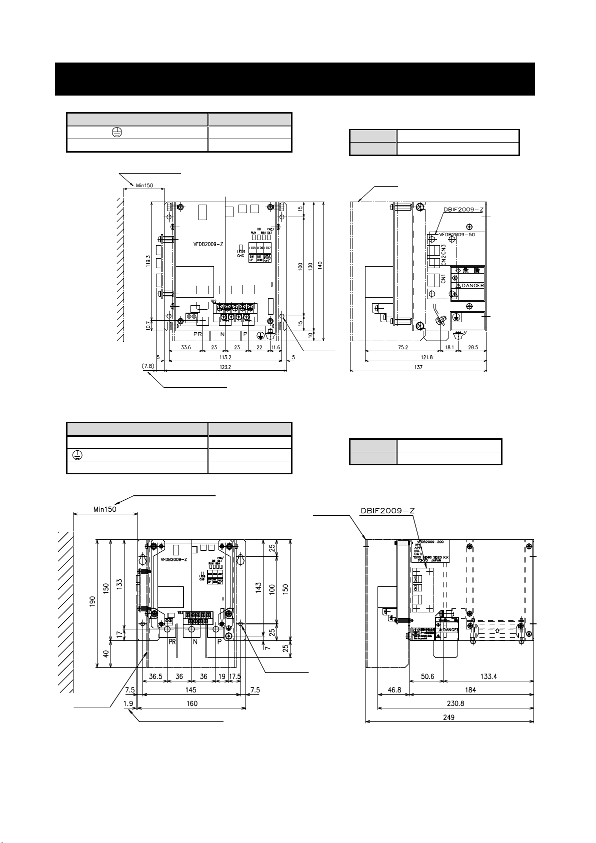
Chapter 4 Outline dimension
○VFDB2009-50
Color
Mansel 5Y7/1
Weight
1.2kg
○VFDB2009-200N
VFDB2009-200F
Color
Mansel 5Y7/1
Weight
4kg
DBIF2009-Z(Option) used
DBIF2009-Z(Option) used
Cover
(Option)
4-M5
Mouting Hole
Cover
(Option) (Option)
Space
Treminal marking
Terminal screws
PR,N,P,
M4
VFDB2009-Z TB2
M3
Treminal marking
Terminal screws
PR,N,P
M8
M5
VFDB2009-Z TB2
M3
DBIF2009-Z(Option) used
Space
DBIF2009-Z(Option) used
Cover
(Option)
4-M4
Mouting Hole
(Option)

15
Chapter 5 Operation
VFDB2009 series Dynamic brake unit operates in the power supply of the middle D.C. voltage of the
inverter. The DB unit becomes a waiting state if the inverter run signal(52MA) is input after the
inverter-middle D.C. voltage rises, and LED “RUN" (Light Emitting Diode) lights. Main switching device(IGBT)
operates when the middle D.C. voltage rises by the regeneration of the inverter, and it rises up to the voltage
set to the DB operating point,and LED “DB" lights. At this time, brake resistor connected to DB unit consumes
regeneration energy, and if inverter-middle D.C. voltage turns into below the voltage that stops DB operation,
a switching device is turned off.
5.1 Explanation of operation
5.1.1 VFDB2009-Z printed circuit board
Figure 5.1 VFDB2009-Z printed circuit board
TB2
DB-IN
DB-ON
86A
52MA
CN1
CN
CN
CN4
CN5
[200V]
[400V]
DB 電圧
CN6
LED1
LED2
LED3
RUN
LED8
LED9
CHG
LED4
DB
86A
FNC/SET
VFDB2009-Z
TB1
LED5
LED6
LED7
SW1
SW2
SW3
UP
DOWN
FNC/SET
DANGER
Hazardous Voltage
RY1

16
Table 5.1 List of parts use and functions on the VFDB2009-Z printed cuicuit board
Name※5
Parts use and functions
CN2
The connector for a change of a power supply voltage system
CN3
CN6
The connector for connection with communication option DBIF2009-Z PC board(※1)
LED8
LED for a normal operation check of CPU (※2)
LED9
CHG lamp (※3)
TB2
The terminal block for DB unit control (※4)
※1: Refer to "7.1 communication option DBIF2009-Z PC board" for a communication option board.
※2: LED8 blinks in a cycle of about 2 seconds, while the VFDB2009-Z board is operating normally. While not
blinking, failure of the loose connection of CN1 or a VFDB2009-Z board can be considered.
※3: The middle D.C. voltage of an inverter turns on LED9 by 30V or more. When the light is not switched on,
failure of the loose connection of CN1 or a VFDB2009-Z board can be considered.
※4: Refer to "3.3 Terminal specifications" for the function of TB2.
※5: Refer to "5.1.2 Display" for LED 1-7 and SW 1-3.
DANGER [VFDB2009-Z PC board]
DB unit cannot be recklessly touched during CHG LED lighting.
Failure to do so may cause electric shock.
Wiring of TB1,CN1,CN4,CN5 are not changed.
Failure to do so may cause electric shock or personal injury and part breakage
17
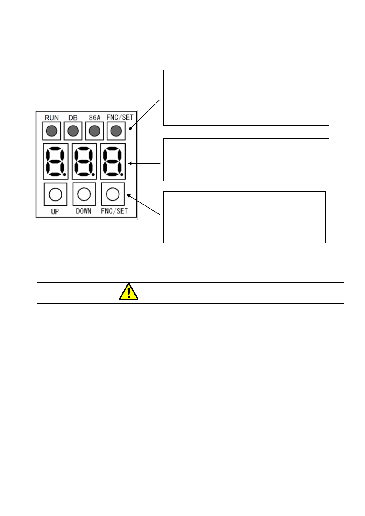
5.1.2 Display
Figure 5.2 Display for indication VFDB2009-Z PC board
DANGER [Operation]
Do not operate any switch with wet hands.
Doing so may expose you to shock hazard.
5.1.3 Operation method of a display for indication
If the power supply of an inverter is turned on, the inverter-middle D.C. voltage will rise and D.C. voltage will
be displayed on the display for indication of DB unit. Setup and adjustment of DB unit are possible by
operating a display for indication.
It changes from the display mode of D.C. voltage to a setup and adjustment of DBunit to setting mode. The
mode can be changed by pushing "FNC/SET" and "UP", and the "DOWN" button.
※"△" in a figure expresses the "UP" button, and "▽" expresses the "DOWN" button.
●Status display LED
RUN:Ligth when DB operation instruction input
DB:Light when during DB unit operation
86A: Light when during protected operation
FNC/SET: Light when setting mode
●Seven segment displays (LED)
Display of D.C. voltage (Vdc) / setting mode / setting
value / protection state
("." Displays a setting item)
●Push button
UP.DOWN:Change of setting mode/setting value
FNC/SET: [Under D.C. voltage display] shifts to another
setting mode.
[Under setting mode] shifts to set-up item.

18
FNC/
SET
FNC/
SET
FNC/
SET
RUN DB 86A FNC RUN DB 86A FNC RUN DB 86A FNC RUN DB 86A FNC
FNC/
SET
FNC/
SET
RUN DB 86A FNC RUN DB 86A FNC RUN DB 86A FNC
△▽
FNC/
SET
FNC/
SET
FNC/
SET
RUN DB 86A FNC RUN DB 86A FNC RUN DB 86A FNC RUN DB 86A FNC
FNC/
SET
FNC/
SET
RUN DB 86A FNC RUN DB 86A FNC RUN DB 86A FNC
△▽
△▽
▽
FNC/
SET
RUN DB 86A FNC
FNC/
SET
FNC/
SET
FNC/
SET
FNC/
SET
△
Power
ON
D.C. Voltage indicate MODE Indicate
MODE Indicate
MODE Indicate
MODE Indicate
DB Operation
voltage
Power supply
voltage Selection
DB Operation Stop
voltage width
Master/Slave
Selection
Station number
Set-up
Low lebel
Calculation
Hight lebel
Calculation
VDC Auto
Calculation
Gain of VDC Offset of VDC
Figure 5.3 The mode change state of a display for indication
If the "FNC/SET" button is pushed during the display of direct-current voltage, it will shift to setting mode
"F10" and LED"FNC/SET" will light up simultaneously. If "UP" or the "DOWN" button is pushed into setting
mode, it will shift to setting mode (F10-F40), and if the "FNC/SET" button is pushed, it will shift to the setting
item in each setting mode.
※If LED"RUN" lights up in set-up mode (DB operation instruction ON), it will switch to D.C. voltage display
mode compulsorily. Moreover, even if it pushes the "FNC/SET" button during lighting of LED"RUN", it does
not switch to setting mode.
Table 5.2 Set-up mode list
Setup mode
Dicription
F10
DB operation voltage setting mode
F20
Power supply voltage selection and Master/Slave selection and Station number set-up
mode
F30
The display gain / offset automatic adjustment mode of D.C. voltage
F40
The display gain / offset hand adjustment mode of D.C. voltage
※Refer to "5.4 Set-up items" for the details in each set-up mode.
19
5.2 Set-up before operation
Please be sure to perform the following setup before using DB unit. DB unit is common use in the power
supply voltage (200V series /400V series) of inveretr and single/parallel operation. Since power supply
voltage is set as 400V series and the mode of operation is set as single operation at the time of shipment, a
setup is changed according to application.
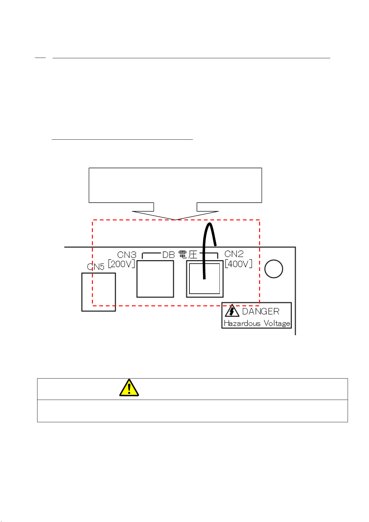
5.2.1 Change of a power supply voltage
Before turing on the power supply of an inverter,please switch connector CN2 and CN3 of
VFDB2009-Z PC board, according to the power supply voltage of the inverter to be used.
Connector is switched corresponding to the power
supply voltage of the inverter to be used.
[400V series]CN2,[200V series]CN3
系 系
Figure 5.4 Power supply voltage change connector
DANGER [Connector]
Before turnig on the power supply of an inverter, the position of a power supply voltage system change
connector is checked.
Failure to do so may cause part breakage.
This manual suits for next models
3
Table of contents
Popular Industrial Electrical manuals by other brands


Murata
Murata GRM0225C1E6R5BA03 Series Reference sheet

Murata
Murata GRT188R61H225KE13 Series Reference sheet

Murata
Murata GRT31CR60J106ME01 Series Reference sheet

HEIDENHAIN
HEIDENHAIN LB 302 Mounting instructions

Murata
Murata GJM1555C1H390JB01 Series Reference sheet

Siemens
Siemens SIVACON 8PS BD01 installation instructions


