Trac Vac CV655-PRO Product guide

8-26-10
Model CV655-PRO
Operating and
Assembly
Manual
Midwest Equipment Mfg.
5225 Serum Plant Road
Thorntown, IN 46071

1
SAFETY RULES
Remember, any power equipment can cause injury if operated improperly or if the user does not understand
how to operate the equipment. Exercise caution at all times when using power equipment.
This symbol means Attention!!!!! It is used to point out safety precautions.
▪ Read and follow all instructions in this manual before assembly or operation of this equipment.
Failure to comply with these instructions may result in personal injury. Keep this manual for future
reference and for ordering replacement parts.
▪Read this instruction manual carefully. Become familiar with the controls and proper use of this
equipment.
▪Read the engine owners manual and safe operation rules before using this equipment.
▪Never allow children less than 16 years of age to operate the Trac-Vac. Children 16 years
and older should operate only under close parental supervision.
▪Do not allow anyone to operate this equipment without proper instruction.
▪Do not allow passengers to ride on the Trac-Vac or on the towing vehicle.
▪Keep children and pets out of area of operation.
▪Check fuel before starting engine. Do Not fill fuel tank indoors, or while engine is running or hot.
Wipe off any spilled fuel before starting engine.
▪Engine and muffler get HOT!Do Not touch! Keep debris from accumulating on or around engine
and muffler to avoid fire hazard.
▪Allow engine to cool before storing in any enclosed area. Never store Trac-Vac with fuel in tank.
▪Do not operate engine if air cleaner or cover is removed, except for adjustments. Removal of the part
could create a fire hazard.
▪Keep hands, feet, face, long hair and clothing out of inlet and discharge areas. There are ROTATING
BLADES inside these openings.
▪Make certain that all moving parts come to a complete stop before cleaning, repairing or inspection.
Disconnect spark plug wire and keep away from plug to prevent accidental starting.
▪If Trac-Vac should become clogged with debris, SHUT OFF ALL ENGINES and wait until impeller
comes to a complete stop before attempting to remove obstruction. Disconnect spark plug wire to
prevent accidental starting.
▪If excessive vibration occurs while operating your Trac-Vac, stop the engine immediately, disconnect
the spark plug wire and allow all moving parts to stop completely before taking the following steps.
A. Inspect for damage.
B. Repair or replace any damaged parts.
C. Check for loose parts and tighten to assure continued safe operation.
▪Check all hardware periodically to insure safe operation.
▪Check cart cover periodically for wear and replace if worn or damaged.
▪Never operate Trac-Vac without intake hose and exhaust hose attached in proper place.
▪Do Not remove exhaust hose or attempt to empty contents of container while engine in running.
▪Keep all shields and guards in place and securely attached.
▪Always wear eye protection (safety glasses or goggles) when operating this equipment.
▪Do Not stand behind unit in exhaust discharge area while engine is running.
▪Do Not operate this equipment while intoxicated or while taking medications that could impair
reactions or senses.
▪Operate this equipment at reduced ground speed on rough terrain, along creeks and ditches and on
slopes to prevent tipping or loss of control.
▪Vehicle stability and braking are affected by the addition of this unit. Do not fill the Trac-Vac to its
full capacity without checking the capability of the towing vehicle to safely pull and stop with the unit
attached.
▪Do Not operate on slopes in excess of 10 degrees. STAY OFF OF STEEP SLOPES!
▪Follow the maintenance instructions outlined in this manual.

2
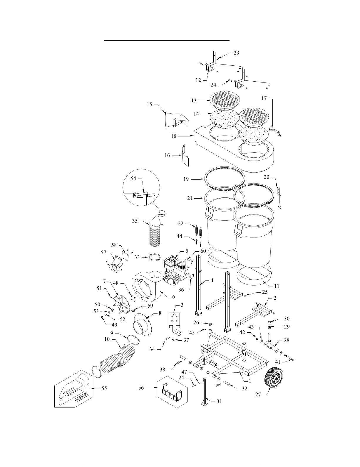
Model CV655-PRO Trac-Vac Parts List
Key Part No. Description Qty.
1 65510 Frame, 655 1
2 47014 Frame, 470-FD 2
3 56510-1 Frame, 565-RH 1
4 47020 Vertical Upright 2
5 56021 Engine, 6.5HP Briggs Intek Pro 1
6 38030 Turbine Housing, Chipper 1
7 56055 Turbine, 1” Bore B/S Chipper 1
8 66010 Inlet, 8”1
9 18119 Hose Clamp, 8” 2
10 86101 Hose, 8” x 60” 1
11 47018 Container Holder, 470 2
12 46217 Top Support 2
13 46227 Filter Support, Double Top 2
14 46228 Filter, Open Mesh 2
15 66238 Exhaust Boot, 662 1
16 46248 Filter Shield 1
17 28104 Handle 1
18 68222 Double Molded Top 1
19 46219 Seal, Molded Top 2
20 46235 Container Latch 2
21 46210 Container, 44 Gallon 2
22 48038 Spring 2
23 56115 Nylon Spacer 6
24 46218 Clevis Pin, Vertical Support 3
25 47019 Bushing, 470 4
26 65032 Bearing, 1” Nylon 8
27 65513 Wheel, 13 x 5.00-6 2
28 65511 Caster Yoke Ass’y 2
29 65514 1” Collar Clamp 2
30 58058 Collar Clamp Cover 2
31 65512 Stand 1
32 28801 Clevis Pin, 1” x 4” 2
33 45101 6” Metal Hose Clamp 1
34 85226 Bent Pin, 5/8” 1
35 66230 Exhaust Hose, 662 1
36 86115 Muffler Deflector (Briggs 5.5 &
6.5HP) 1
37 1101301 Hairpin Cotter, 1/2” 1
38 1101302 Hairpin Cotter, 1” 2
41 6250152 Caster Bolt, 5/8” x 6 ½” 2
42 6251101 Caster Nut, 5/8” Nylon Insert 2
Key Part No. Description Qty.
43 6250800 Caster Washer, 5/8” FLW 4
44 3120518 Eyebolt, 5/16” x 2 1/4” 4
45 3122501 Grease Zerk, 5/16” 2
47 11100 Hairpin Cotter, 5/16” 1
48 3120612 Housing 4
49 3760110 Turbine Bolt (6.5HP Briggs Pro) 1
50 56107 Turbine Washer 1
51 3750238 Turbine Set Screw 1
52 2501716 Key Stock (6.5HP Briggs) 1
53 3750801 Turbine Lock Washer (6.5HP
Briggs Pro) 1
54 56052 Connector Clip, Exhaust Hose 1
55 ***-8 Discharge Chute, 8” (tractor
specific) 1
56 656** Hitch Kit, 655 (tractor specific) 1
57 58035 Chipper Inlet 1
58 38066 Chipper Inlet Guard 1
59 88041 Chipper Knife (included w/turbine) 2
60 58075 Engine Guard 1
45133 Warning, Stop Engine 1
45131 2” x 8” Trac-Vac White on Clear 2
45130 3” x 12” Trac-Vac White on Clear 2
48096 Danger 2
Optional Accessories:
Key Part No. Description
38 190 6” Remote Pickup Assembly for 8” hose
3
CV655 Parts Breakdown

4
Model 655- Trac-Vac Assembly Instructions
1. Slip caster assembly (28) through the receiver tube on the frame (1). Secure with 1” collar clamp, slip plastic
cover over collar clamp. Repeat for the other caster. Slip stand (31) into receiver on main frame and secure with
3/8” x 2 1/4” clevis pin (24) and 5/16” hairpin cotter (47). See Fig 1
2. Attach hitch (56) to rear of tractor as shown in hitch instructions. Hold frame (1) up to hitch (once installed on
tractor) aligning the horizontal receiver tubes up with 1” diameter holes in hitch arms, secure with 1” clevis pins
and hairpin cotter clips. Set FD frame (2) onto main frame (1). Align holes in FD-frame (2) with holes in main
frame (1) as shown and loosely secure with 2-5/16” x 3/4” bolts, flatwashers and whizlock nuts on the “T” side of
FD-frame, and with 5/16” square bend u-bolt and whizlock nuts on the leg of the FD-frame. Do not tighten.
Repeat procedure for second FD-frame. Note: be sure and use the holes on FD-Frame illustrated in Fig. 2 to
secure them to the main frame. See Fig. 2
3. Slip vertical upright (4) over leg in FD-frame (2) align the holes and loosely secure with 3/8” x 2 1/2” bolts
flatwashers and whizlock nuts. Note: eyebolt brackets on the upright should be positioned toward the containers.
Do not tighten. See Fig. 3
4. Set container holder (11) onto “T” side of FD-frame (2) and align holes. Slip Bushings (25) through the mount
holes of both the container holder (11) and the FD-frame (2) and secure with 5/16” x 1” bolt, 5/16” flatwashers
and a 5/16” locknut. Tighten bolts until the holder will support container in a tilted position. See Fig. 4
5. Place containers (21) into container frames, rotate the handles to the inside of the vertical uprights. Spin 5/16” nut
onto the eyebolt (44) about half way. Slip eyebolt with nut through the hole in the bracket on the side of vertical
upright (4) and secure with a 5/16” whizlock nut. See Fig. 5
6. Set top assembly on containers (21) with top support bracket capturing the vertical upright (4). Align 1/2” hole on
top support to 1/2” hole on vertical upright (4). Secure molded top with 1/2" x 2 1/2" HHC’s and nylock nuts.
Tighten until slight drag can be felt when pivoting molded top. See fig. 6
7. Pivot top up and attach springs (22) to eyebolts (44) and spring retainers on top support (12). Lower top assembly
to operating position and immediately slip clevis pin (24) thru locking pinhole on top support. Secure pin with
1/8" x 1" cotter key. Attach container latch (20) to molded top with 1/4” x 1/2” truss head bolt and 1/4” whizlock
nuts. Slip exhaust boot (15) into molded top and secure with 1/4” x 3/4” bolts, 1/4” flatwashers and whizlock nuts.
With molded top assembly setting flat on the containers and latched, tighten all bolts left loose in earlier
assemblies (vertical upright and FD-frame bolts). Once tightened rotate top up and down a few times to see if
proper alignment has been achieved. If proper alignment was not achieved loosen vertical upright and FD-frame
bolts and try again. See Fig. 7
8. Bolt Engine ass’y to frame (3) with 5/16” x 1 1/4” bolts and 5/16” locknuts. Note: bolt the engine assembly into
the holes closest to the end of the engine plate. Slip engine/frame assembly into receiver on main frame (1).
Secure with 5/8” bent pin (34) and 1/2” hairpin cotter (37). See Fig. 8
9. Slip metal hose clamp (33) up onto bottom of exhaust hose (35) and slip both down over exhaust neck on blower
housing. Slip other end of exhaust hose (35) into exhaust boot (15) bolted into molded top assembly. Once
achieved tighten bolts in metal hose clamp securing exhaust hose to the blower housing, if installed properly the
connector clip (54) on the top of the exhaust hose should not have to be clipped to hold the hose into the exhaust
boot on molded top unless unit is running (pressurized). Attach discharge chute to tractor, slip intake hose (10)
over inlet and secure with 8” band clamp (9). Cut hose to fit to discharge chute, slip onto neck on discharge chute
and secure with 8” band clamp. See Fig. 9
10. Read engine operation instructions and service engine before starting

5
Fig . 1 Fig . 2 Fig . 3
Fig . 6
Fig . 5Fig . 4
Fig . 7 Fig . 8 Fig . 9
1 " C o lla r
C la m p (2 x)
C o llar C lam p
C o ve r ( 2x )
H a irp in C o tter
K ey , 5/16 "
3/8" x 2 1/4"
C l ev is P in
5/16 " x 3 /4 " H exb olt (4 x)
5 /1 6 " S q u a re B e nd U - b ol t ( 2x )
5/16 " W h izlo ck nu t (8 x)
H a irp in C o tter, 1" (2 x)
1" x 4" C lev is Pin (2 x)
3/8" x 2 1 /2 " H exb olts (4 x)
3/8" W hizloc k n uts (4 x)
5 /1 6 " F la tw a sh e r (4 x )
3 /8 " F la tw a sh e r (4 x )
5/16 " x 1 " H e xbo lt (4 x)
5 /1 6 " L o ck nu t ( 4x )
S p a ce r (4 x )
5/16 " W h izloc k N ut (4x )
5 /1 6 " F r ee n u t ( 4x )
E yeb olt, 5/1 6" x 2 1/4 (4 x)
1/2" x 2 1/2"
H ex bo lt (2 x)
1/2" N ylo ck (2 x)
1/4" x 1/2" T russ hea d S cre w (4 x)
1/4" x 3 /4 " H ex bolt (4 x)
1/4" W hizloc k
N ut (8x )
S p rin g ( 4 x)
1/8" x 1 "
C o tt er P i n ( 2x )
5 /8 " B e n t P i n
H a irp in C o tter, 1/2 "
M etal H o se C lam p
D is ch arg e C hu te
8 " B a nd C la m p (2x )
In le t
C o nn ec to r C lip
5 /1 6 " F la tw a sh e r (8 x )

6
C A U T IO N !!!!
SP IN N IN G B L A D E
CHIPPER VAC INSTRUCTIONS
The chipper components on your chipper vac have been fully assembled at the factory.
The chipper operates most efficiently at 20% of normal vacuuming air flow. To reduce air flow, you may want to
remove the chute from the mower deck and face its opening to the ground.
Your chipper vac is designed to accommodate limbs up to 2 ½” in diameter.
To remove the chipper blades for sharpening, detach the three 3/8” whizlock nuts and lift off the chipper chute.
Remove the two blades using a 3/16” allen wrench. Sharpen blades and reattach. Make sure blades are fastened
securely.
Keep in mind to periodically tighten all bolts.
Listen for unusual vibration of air turbine. If excessive vibration is present, stop engine and check for damage.
CAUTION!!!
*ROTATING CUTTING BLADES*
*KEEP BODY PARTS AND CLOTHING AWAY FROM DRIVEN PARTS IN MOTION*
*AVOID LOOSE CLOTHING*
*WEAR APPROPRIATE GLOVES, EYE AND HEARING PROTECTON*
*ALWAYS STOP ENGINE AND DISCONNECT SPARK PLUG TO SERVICE*

7
T R O U B L E SH O O T IN G
P R O B L E M P O SSIB L E C A U S E C O R R E C T IV E A C T IO N
E ngin e fails to start 1. Spark p lug w ire discon nected
2. Fuel tank em p ty
3. Faulty spark plug
1. C on nect w ire to spark p lug
2. F ill tank w ith clean fuel
3. C lean, adjust gap or replace
L o ss o f pow er or
erratic o peration 1. Sp ark plu g w ire loose
2. B locked fuel line
3. W ater or d irt in fuel system
4. D irty air cleaner
5. C arb uretor out of adjustm ent
6. U nit running o n ch oke
1. C on nect & tigh ten spark plu g w ire
2. C lean fuel line
3. D isconnect fu el line at carbu retor
d rain fu el tank. R efill w ith fresh
fuel
4. Serv ice air cleaner (refer to engine
m anual)
5. A djust carbu retor (refer to eng ine
m anual)
6. M ove chok e lever to O F F po sition
E ngin e o verheats 1. C arb ureto r n ot ad justed
pro perly
2. E ng ine oil level low
3 . O P era tin g b elo w fu ll R P M
1. A djust carbu retor (refer to eng ine
m anual)
2. F ill crank case w ith proper o il
3. R un th ro ttle full o pen.
E xcessive vibration 1. D am aged turbine or loo se
p arts 1. S top eng ine im m ed iately and
d isconn ect spark p lug w ire. T ig hten
all b olts & nu ts. M ake necessary
repairs. If vibration continu es, have
u nit serviced by an au thorized dealer.
U nit w o n't p ick up. 1. D ischarg e ch ute clogg ed
2. F oreig n object lod ged in
tu rb ine.
3. C on tainer full
1. S top engin e & d isconn ect spark plu g
w ire. C lean inside of disch arge
chute.
2. S top engin e and disconnect sp ark
p lug w ire. R em ov e lo dged object
in tu rbin e.
3. S top engin e and em p ty co ntainer.
N O T E : P lease con tact the nearest authorized serv ice dealer for repairs beyond the m inor adjustm ents abo ve.

8
OPERATING PROCEDURE
1. Follow engine manufacturer's instructions in preparing engine for operation.
2. Inspect area to be vacuumed and pickup all harmful objects and litter. Rocks and other harmful debris can do
serious damage to vacuum assembly and cause bodily injury.
3. For best vacuuming results operate tractor at manufacturer's recommended speed for best cutting. If grass is high,
mow first and vacuum on the second pass.
4. When mowing keep discharge chute to the outside of cutting area for better cut and efficient pickup of grass
clippings and leaves.
5. Your vacuum is preset to run at approximately 3200-RPM at no load. Do not slow down engine.
6. SHUT OFF ENGINE TO UNLOAD.
7. When operating tractor on slope or grade, exercise extreme caution. Do not cut across grade or slope. Mow directly
up and down hills.
8. Periodically check all fasteners for tightness.
9. Listen for unusual vibration of engine or air turbine. If excessive vibration is present, STOP engine and check for
damage to turbine fan.
10.Always shut off tractor engine and vacuum engine before servicing.
11.Replace deflector shield when discharge chute is removed.
12.When removing clogs, SHUT OFF ALL ENGINES.
EXTENDED STORAGE PROCEDURES
1. Wash and clean vacuum, and lubricate any lubrication points.
2. Drain fuel from the tank and run vacuum until fuel is exhausted in carburetor.
3. Drain and change the engine oil.
4. Clean tires and check pressure. Raising and supporting unit with weight off tires is recommended.
5. When storing a unit with Rubbermaidcontainers, leave containers latched to top.
TRAC VAC WARRANTY POLICY
Midwest Equipment Mfg. will repair or replace, free of charge, any part, or parts that are defective
in material or workmanship or both for a period of one year residential use, and 90 days for
commercial and rental use. The purchaser will pay transportation charges on parts submitted for
replacement under warranty. For warranty service, contact your local dealer from whom the unit
was purchased. There are no other express or implied warranties. Some states do not allow
limitations on how long an implied warranty lasts, and some states do not allow the exclusion or
limitation of incidental or consequential damages, so the above limitation and exclusion may not
apply to you. This warranty gives you specific legal rights and you may also have other rights,
which vary from state to state.
MIDWEST EQUIPMENT MFG.-5225 Serum Plant Rd.-Thorntown, IN 46071
Phone: 1-800-Trac-Vac
Table of contents
Other Trac Vac Lawn Mower manuals


Popular Lawn Mower manuals by other brands

MTD
MTD 114-040A Owner's operating service instruction manual

Spearhead
Spearhead RHD Series Handbook & Parts Manual

Craftsman
Craftsman 247.28881 Operator's manual

Yard force
Yard force COMPACT 280R installation guide

Duramaxx
Duramaxx 84881 owner's manual

Craftsman
Craftsman 316.773800 Operator's Operator's manual


Scag Power Equipment
Scag Power Equipment Magnum III Operator's manual

Troy-Bilt
Troy-Bilt RZT SERIES ZT42 Operator's manual

Poulan Pro
Poulan Pro Poulan Pro 961140016 Repair parts manual

Husqvarna
Husqvarna Royal 46 RC Operator's manual

Craftsman
Craftsman EZ3 917.259551 owner's manual

Toro
Toro 30608 30644 Operator's manual