4Installation
4.1 Mechanical Installation
Tracerco Specialist Measurement Project Engineers will work with you to capture your
system requirements. This will include producing a system general arrangement drawing
that will detail the mounting positions of the source container(s) and PRI150 radiation
detectors. Tracerco Project Engineers will also advise on bracket design for mounting the
equipment to the vessel.
Any frameworks and/or structures, both external and internal to the vessel (for example,
stiffening rings, platform supports, agitator, and so on), should be identified and the
details passed on to the Tracerco Project Engineer. The system will have to be designed
to avoid these structures in order to obtain optimum performance and allow delivery of
the correct source size to achieve this performance.
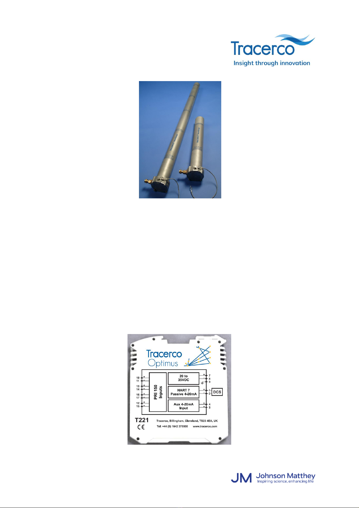
4.1.1 Source Container(s)
The source container is mounted on brackets, typically attached directly to the vessel.
Attention should be made to the following:
•Mounting brackets must be fabricated exactly as shown on the bracket drawings
supplied by Tracerco. Errors in fabrication could lead to significant degradation in
system performance.
•Brackets must be constructed so that the gap between the front face of the source
container and the vessel is fully enclosed. This is to provide the necessary
protection from scattered radiation and also to prevent finger access to the source
beam.
•The front mounting plate must incorporate a hole as advised by Tracerco to avoid
unnecessary attenuation of the radiation beam.
•There must be a clearance of at least 250mm (10”) on the side of the container
that holds the arming rod mechanism. This is to allow the arming rod mechanism
to be opened and closed. If this is not possible, then Tracerco must be contacted
to advise on repositioning whilst maintaining optimum performance.
WARNING! Source containers contain extremely dense materials and therefore are heavy.
Suitable lifting precautions must be taken when mounting.
4.1.2 PRI150 Radiation Detector(s)
The PRI150 radiation detectors are mounted on brackets, typically attached directly to the
vessel. Attention should be made to the following:
•There are labels placed at the end of the detectors (MOUNT BRACKET
ABOVE/BELOW THIS LINE) showing the limits of the sensitive region. Where ever
possible, mounting brackets should be placed outside of the sensitive region.
•Mounting brackets must be fabricated exactly as shown on the bracket drawings
supplied by Tracerco. Errors in fabrication could lead to significant degradation in
system performance.