6.AMD-xx-TD series more than one section high will be
shipped separately in individual sleeves. Using the provided
RJ-45 cable connect the bottom probe on the top section to
the top probe on the bottom section. The bottom section has
the transmitter mounted to it.
Do not twist
or bow. Mount
damper plumb
in the opening.
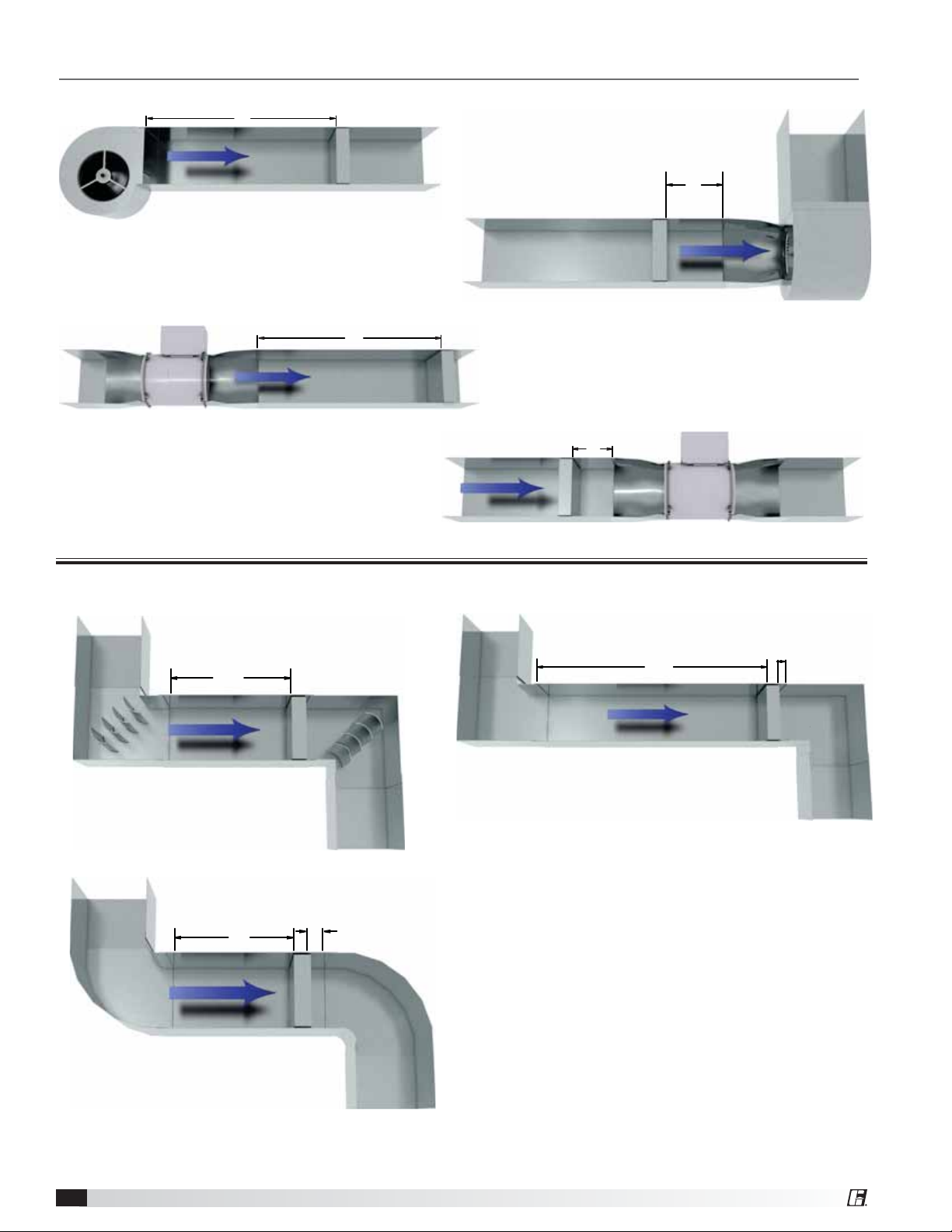
AB
AF = BE
AB = CD
CD
EF
Installation - Failure to follow instructions will
void all warranties
1. Ensure the AMD-XX-TD series dampers is mounted
with measurement probes upstream of the damper.
2. Your duct opening or opening square should measure
1/4 inch (6mm) larger than damper dimension and
should be straight and level.
3. Use shims between damper frame and duct opening
or opening space to prevent distortion of frame by
fasteners holding it in place. Brace at every horizontal
mullion and vertically brace at every 8 feet (2.4m) of
damper width for strength. Dampers in high velocity
(2000 fpm [610m per second]) may require more
bracing.
NOTE: Greenheck dampers are specifically designed
and engineered for structural integrity based on model
and conditions. Attachment, framing, mating flanges,
and anchoring of damper assemblies into openings,
ductwork, or walls is the responsibility of the installer.
Design calculations for these retaining and supporting
members should be determined by field engineers for
that particular installation.
4.Individual damper sections, as well as entire multiple
section assemblies must be completely square and
free from racking, twisting, or bending. Measure
diagonally from upper corners to opposite lower
corners of each section.
5.Damper blades, axles, and linkage must operate
without binding. Before system operation, you can
cycle dampers after installation to assure proper
operation. On multiple section assemblies all sections
should open and close simultaneously.
Setup and Operation for AMD-xx-TD
Series Damper
All AMD-xx-TD’s are supplied with a Vari-Green®
airflow rate transmitter that is factory wired to one or
more Vari-Green airflow measurement probe(s). The
transmitter has been configured at the factory with
customer supplied parameters. For normal applications
the transmitter’s configuration should not need to be
modified in the field. However, if field configuration is
necessary please reference the Vari-Green transmitter
Installation, Operation, and Maintenance Manual
available at www.greenheck.com.
Once electrical power is applied, the transmitter will
go through a standard start-up sequence during which
it will identify and enable each airflow sensor. This will
take approximately 25 seconds. Once the start-up
sequence has been complete, the transmitter’s display
will show the measured volumetric airflow rate, velocity,
and ambient air temperature (see below). Under normal
operation, a blinking green dot in the upper right corner
of the display signifies that the processor is functioning
correctly, and two flashing arrows indicate that the
sensor(s) and transmitter are communicating normally.
You can order AMD-xx-TD’s with or without a factory
supplied controller. When a factory supplied controller
is ordered, the controller can be configured for either
analog operation or operation via a BACnet MS/TP
connection. Setup and operation for these different
options are described on the following pages.
AMD-xx-TD Series 3