TRAILPARTS Credo User manual

INSTALLATION GUIDE
Electric Drums &
Hydraulic Disc or Drum
Please return to customer once install completed
Read instructions before installation
NZ: 3500KG GVM | AU: 4500KG GVM

2
AU Freephone 1300 538 598
E sales@trailparts.com.au
www.trailparts.com.au
Index
Page 7
Page 13
Page 16
Page 9
Page 8
Page 10-12
Page 14-15
Commission / Testing
Troubleshooting
Recoding Touch Screen Controller
Serial Number Locations
Warranty - T&C - Maintenance
Hrdraulic Pre-Assembled Wiring Diagram
Electric Wiring Diagram
Hydraulic Wiring Diagram
Page 6
Pre-Installation
Page 5
Orientation Guide
Page 4
Page 3 Introduction to Credo
Note: This instruction Book is
for Credo units with a serial
number over 4500

3
NZ Freephone 0800 487 245
E sales@trailparts.co.nz
www.trailparts.co.nz
The Credo is a trailer brake controller. It is mounted directly on the trailer for maximum reliability
and transmitts to a wireless controller for universal vehicle compatibility. It receives all the standard
trailer light signals, charges the battery from the tail circuit and switches on the brakes when
the brake circuit is on. The brakes are modulated from the internal accelerometer to the current
settings the user has set on the controller. It provides a breakaway switch circuit and provision for
emergency braking via the in-cab, touch screen controller. The controller provides feedback of any
fault conditions, settings adjustments, and emergency braking control.
Wireless remote design with an encoded
wireless link.
Universal vehicle connection that only
needs standard trailer plug wiring on
the vehicle and no hard-wired controller
permanently mounted in the vehicle.
Internal load resistors to present a load to
bulb sensing circuits in late model vehicles.
Buck/Boost Battery Charger means
trailer battery is always charged correctly
regardless of vehicle voltage.
Output protection to prevent damage from
trailer wiring short circuits.
Can operate both Electric and Electric/
Hydraulic Braking systems.
Real feedback of any trailer faults without
specialist vehicle wiring.
Trailer stop lamps are powered when
breakaway switch is activated.
Controls and eliminates flashing trailer
lights caused by some vehicles when using
LED lamps.
What is the Credo?
Credo Design Features:
4
AU Freephone 1300 538 598
E sales@trailparts.com.au
www.trailparts.com.au
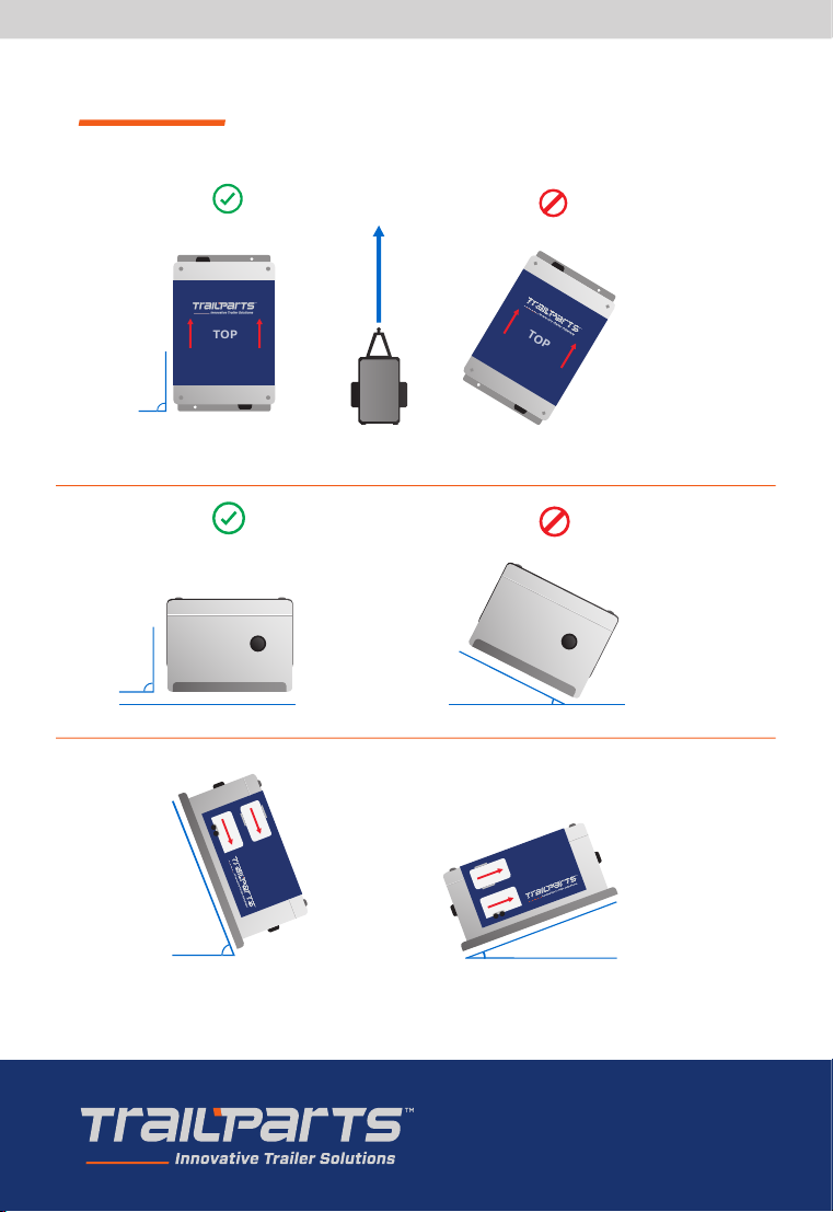
Orientation Guide
SIDE
Direction of Travel
SIDE
Back can be up to
70 Degrees Up
Back can be up to
20 Degrees Down
20
o
70
o
OR
TOP
TOP
Direction of Travel
Must be mounted straight longitudinally, i.e. parallel to direction of travel
INCORRECT
CORRECT
90o
FRONT
FRONT
Unit Must Be Level
Laterally
INCORRECT
CORRECT
90
o
Direction
of travel
Must be
mounted
straight
longitudinally,
i.e. parallel to
the direction of
travel
FRONT
FRONT
Unit Must Be Level
Laterally
INCORRECT
CORRECT
90
o
Unit must be
level laterally
Direction of travel
Back can be up
to 70 degrees up
Back can be up to
20 degrees down
5
NZ Freephone 0800 487 245
E sales@trailparts.co.nz
www.trailparts.co.nz
Unit must be
level laterally
*Extention from supplied length
Do not Earth to Chassis.
Keep any Electric/Hydraulic actuators as close as possible to the controller.
Keep Battery as close as possible to the controller.
Only use LED trailer lights with Credo brake controller.
Use a dedicated battery – using the brake controller battery for other systems can compromise
that safety of the braking system if another fault occurs that is not related to the brakes,
Keep wiring sizes to above minimums.
Wiring Notes:
Circuit Minimum size Max Length
Vehicle Connection*10A / 1.0mm² 3m
Tail/Marker Lights 5A / 0.5mm² 10m
Battery 20A / 2.0mm² 1m
Electric Drums 15A / 1.5mm² 8m
Hydraulic Actuator 25A / 4mm² 0.5m
Mount to a metal frame member to allow conduction of heat from load resistors away from the
Credo – failure to do so means that the Credo can overheat.
Bolt to a solid frame member that will not flex during vehicle motion.
Trailer tail and marker Lights must be LED with a maximum draw of 0.6A – any additional lights
will need to be connected in before the controller.
Mount the controller on the trailer draw bar with a clear line of sight to the vehicle – under
the chassis or behind and or under any metallic objects that shields the controller will cause
interference in the wireless signal. If using a plastic box make sure that there is a way to
conduct heat away from the base of the Credo. This can be by 4 bolts connecting to a metal
chassis member directly below the Credo of a significant size.
Mounting / Installation Requirements:
6
AU Freephone 1300 538 598
E sales@trailparts.com.au
www.trailparts.com.au
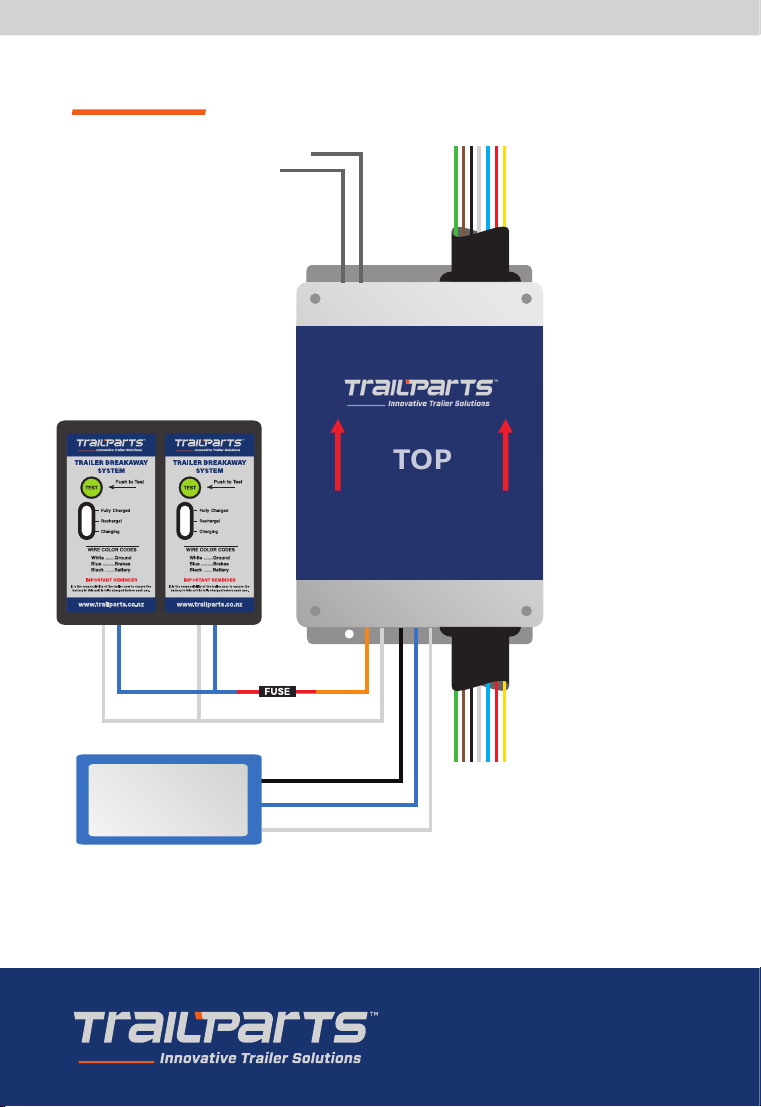
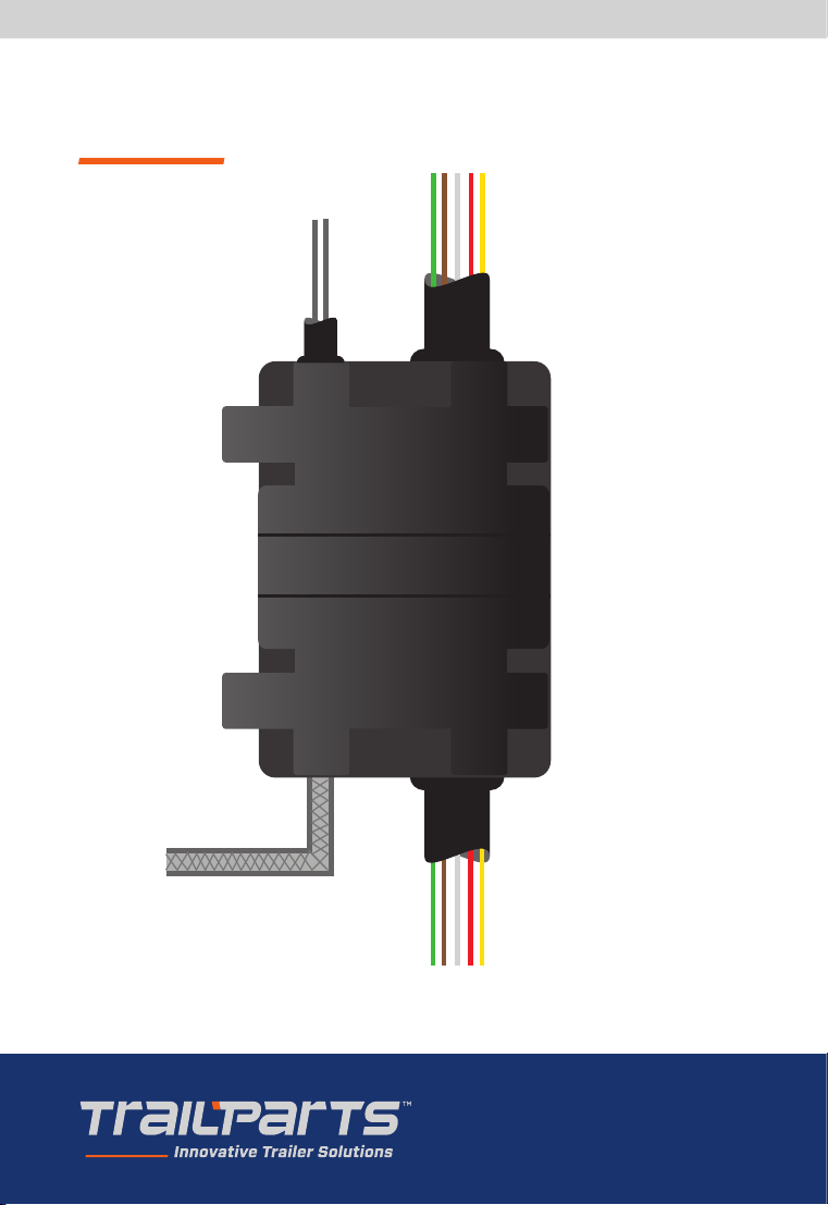
Actuator must not have isolator fitted as one is built into the controller on this version.
All unused wires on pump and Credo must be isolated.
TOP
Connect one grey to each side
of the breakaway switch
White to Earth
Green - Right Indicator
Brown - Tail light
Black - Reverse (Optional)
White - Earth
Blue - Not used
Red - Stop light
Yellow - Left Indicator
Green - Right Indicator
Brown - Tail light
Black - Reverse
White - Earth
Blue - Not used
Red - Stop light
Yellow - Left Indicator
Connect trailer lights to
7 core output
Battery Requirements:
2x5Ah or 1x12Ah or bigger
30 amp blade fuse
required on orange wire
Must only be used for
credo connection
Hydraulic Pump
There should be no more
than 2.5 metres of cable
between the controller
and the trailer plug to
avoid voltage drop.
White Negative
Orange
Positive
Isolate any other wires
Blue Power
Black Positive
Hydraulic WIring Diagram
7
NZ Freephone 0800 487 245
E sales@trailparts.co.nz
www.trailparts.co.nz
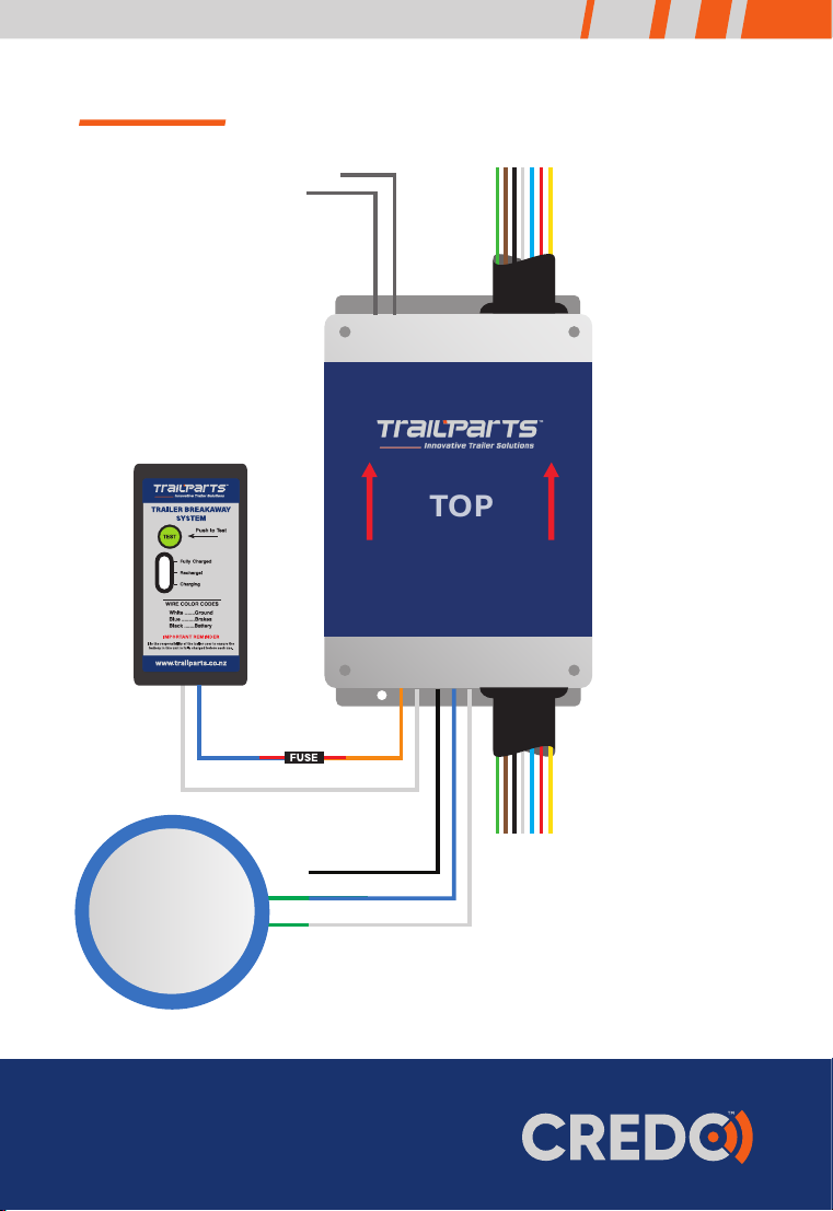
TOP
Connect one grey to each side
of the breakaway switch
White to Magnet
Green - Right Indicator
Brown - Tail light
Black - Reverse (Optional)
White - Earth
Blue - Not used
Red - Stop light
Yellow - Left Indicator
Green - Right Indicator
Brown - Tail light
Black - Reverse
White - Earth
Blue - Not used
Red - Stop light
Yellow - Left Indicator
Connect trailer lights to
7 core output
Electric Drum magnet wires
are interchangeable
Battery Requirements:
1x5Ah or bigger
30 amp blade fuse
required on orange wire
Must only be used for
credo connection
Electric Drum
There should be no more
than 2.5 metres of cable
between the controller
and the trailer plug to
avoid voltage drop.
White Negative
Orange
Positive
Blue to Magnet
Black Not Used
All unused wires on the Credo must be isolated.
Electric WIring Diagram
8
AU Freephone 1300 538 598
E sales@trailparts.com.au
www.trailparts.com.au
All unused Credo wires must be isolated.
FRONT
REAR
Credo Hydraulic Pre-assembled
Wiring Diagram
Connect wire tails from rear to
trailer tail-lamps
Connect brakeline to brake
actuator port
Connect 2-core cable to
breakaway switch
Green - Right Indicator
Brown - Tail Light
Black – Reverse
White - Earth
Blue - Service Brake
Red - Stop Light
Yellow - Left Indicator
Green - Right Indicator
Brown - Tail Light
Black – Reverse (Optional)
White - Earth
Blue - Not Used
Red - Stop Light
Yellow - Left Indicator

9
NZ Freephone 0800 487 245
E sales@trailparts.co.nz
www.trailparts.co.nz
Note: This brake controller is controlled by inertia / deceleration which means there is no response
if the trailer stationery.
Stationery Testing:
Breakaway switch
gives 97% output which should lock the brakes to their maximum any attempt to tow the trailer
should result in the wheels skidding when unladen.
Emergency Stop Override Button
The brakes are applied at 75% of the current gain setting (i.e 99% gain will give a 74% brake
output) dierent settings and brake outputs can be tried by adjusting the gain level.
Road Testing:
Empty Trailers start with 25% Gain and Sensitivity of 3. Adjust to suit as you drive.
Loaded Trailer start with at least 50% Gain and Sensitivity of 3 and adjust to suit.
General Notes:
The trailer should not be holding the vehicle back or ‘pulling’ the vehicle when the brakes are
used. If so the brakes will be experiencing excessive wear and load.
Electric Drums may need bedding in when new or replaced. This can be done setting the Gain
to about 30-35% and holding the emergency stop for approx. 0.5km while travelling at 40-
50kmh. Do this in a quiet area where there is little other traic.
Commission / Testing:

10
AU Freephone 1300 538 598
E sales@trailparts.com.au
www.trailparts.com.au
Troubleshooting
Fault Possible Causes Repairs/Checks
In-cab controller shows
‘Low Trailer Battery’
warning.
(old style In-cab Controller
shows Eb Error)
OR
No tail lights / tail lights
go out when brakes are
applied.
In-cab controller shows
‘Please Drive with Your
Headlights On’ message,
even though the headlights
are on
(old style In-cab shows
Ec Error).
Battery is excessively
discharged.
Bad connection between
trailer mounted brake
controller and battery.
Blown battery fuse.
Poor connection on battery
terminals.
In-cab controller and Trailer
mount controller serial
numbers don’t match.
Faulty trailer plug.
In-cab controller cannot
communicate with the
trailer mounted controller
due to interference.
Incorrect wiring by-passes
controller.
Check battery is over 12.5V when
disconnected. If lower replace the
battery.
Check if battery is charging by
measuring the battery voltage
on the trailer. Measure with the
vehicle disconnected which should
be at least 12V, then plug into the
vehicle and turn on the lights. After
30 seconds there should be a rise
in the battery voltage that shows
the Credo pushing charge into the
battery. The battery voltage should
peak at 14.3V.
Check leads, fuse holder and any
connections between the battery
and controller for poor / corroded
connections. Any high resistance
joins will cause excessive voltage
drop to the controller under
braking resulting in the ‘Low
Battery’ error.
Recode the Serial number on the
In-cab remote.
If they do not match then follow
instructions on page 14/15.
Check trailer plug pins are not
corroded or crushed in, and either
spread the pins, remove corrosion
or replace the plug.
Check the controller to In-cab
connection by taking the in-cab
unit back to beside the trailer
mounted controller, if still error is
still present controller needs to be
replaced or repaired.
Check the vehicle connection
goes to only the trailer mounted
controller and all tail and marker
lights from the controller lights
output.

11
NZ Freephone 0800 487 245
E sales@trailparts.co.nz
www.trailparts.co.nz
Fault Possible Causes Repairs/Checks
Brakes randomly come on
and lock up.
Braking output on In-cab
controller stays at ‘--‘ on
the screen when brakes are
applied.
In-cab Controller shows
‘00’ or higher numbers
when brakes applied but
no braking happens.
Faulty Break-away switch.
Faulty Break-away wiring.
In-cab controller has
‘emergency stop’ button
pressed.
Faulty trailer plug / vehicle
connection.
Incorrect wiring bypasses
controller.
On electric drums – Faulty
wiring or magnets.
On hydraulic actuator driven
brakes – Faulty wiring or
isolator if fitted.
Check breakaway switch and
wiring for a short circuit. Replace
any faulty components or wiring.
Check the breakaway switch is not
full of water and dirt. Any leakage
of voltage in the breakaway
circuit due to water ingress can
cause unexpected behaviour on
Hydraulic / Electric systems.
Make sure In-cab controller is
securely mounted on vent holder
and emergency stop button not
inadvertently pressed.
Check and repair trailer plug and
vehicle socket and associated
wiring – replace any faulty parts.
Check vehicle connection goes
directly to the controller and does
not bypass the controller.
On electrics check wiring
and drum magnets for faulty
connections. Typical magnet
resistance is approx 2.8 Ohms. 2
Magnets together is 1.4 Ohms and
4 is 0.7 Ohms.
On Hydraulic the Blue signal wire
should be checked for voltage
when the emergency stop being
is pressed. If there is some voltage
and there is no brakes then call for
assistance.
Wheel locking up on one
side of the trailer.
Wiring connected to one
side of the trailer first and
then to the other.
Connect magnets into a star
connection.

12
AU Freephone 1300 538 598
E sales@trailparts.com.au
www.trailparts.com.au
Troubleshooting
Fault Possible Causes Repairs/Checks
No braking and trailer can
still be rolled when the
break away pulled – no low
battery fault.
In cab Remote shows “No
SD Card” Error.
*Serial 4500 onwards*
Any tail-light outputs or
brake or Hydraulic pump
power not giving any
power.
Drums are new and need
bedding in.
Broken connection to the
drum magnets.
Shorted Drum Magnet.
SD card has been dislodged
or is faulty.
Output has been shorted
and output has locked out.
Set controller to lower setting of
around 25-40 and then drive at
a low speed of 40-50kmh while
holding the emergency stop
button. Drive 0.5 -1km. This will
heat the brakes up and bed in the
shoes.
Check all connections to the
drums.
Check resistance of each magnet
individually typically resistance is
2.8Ohms.
Remove the back cover of the in
cab remote and take out batteries
and unplug from any power. Check
the SD card is properly inserted
and try removing and reinserting.
Make sure it is clicked in properly.
Replaced batteries, back cover and
power up to check operation.
If reinserting the SD card does not
help the SD card may be faulty
and the in cab remote needs to be
replaced.
Repair the fault and disconnect
from the vehicle and the
trailer battery. While the unit is
depowered the output will be reset.
Reconnect battery and plug into
vehicle to test.

13
NZ Freephone 0800 487 245
E sales@trailparts.co.nz
www.trailparts.co.nz
Incab Controller:
For serial numbers 1-2700 the serial number is located on the grey base of the controller or at the
bottom of the black plate on the back if it is a touch screen controller.
Serial numbers 2701- when the touch screen controller is first connected to power the serial number
is shown on the 4th screen that displays on start up.
Trailer Mount Controller:
Either engraved/stamped into the alloy base plate or etched into the front face of the trailer
mount controller.
Serial Number Locations

14
AU Freephone 1300 538 598
E sales@trailparts.com.au
www.trailparts.com.au
-
-
EMERGENCY
STOP
LESS MORE ADJ.
+
GAIN SENS.
ZzP
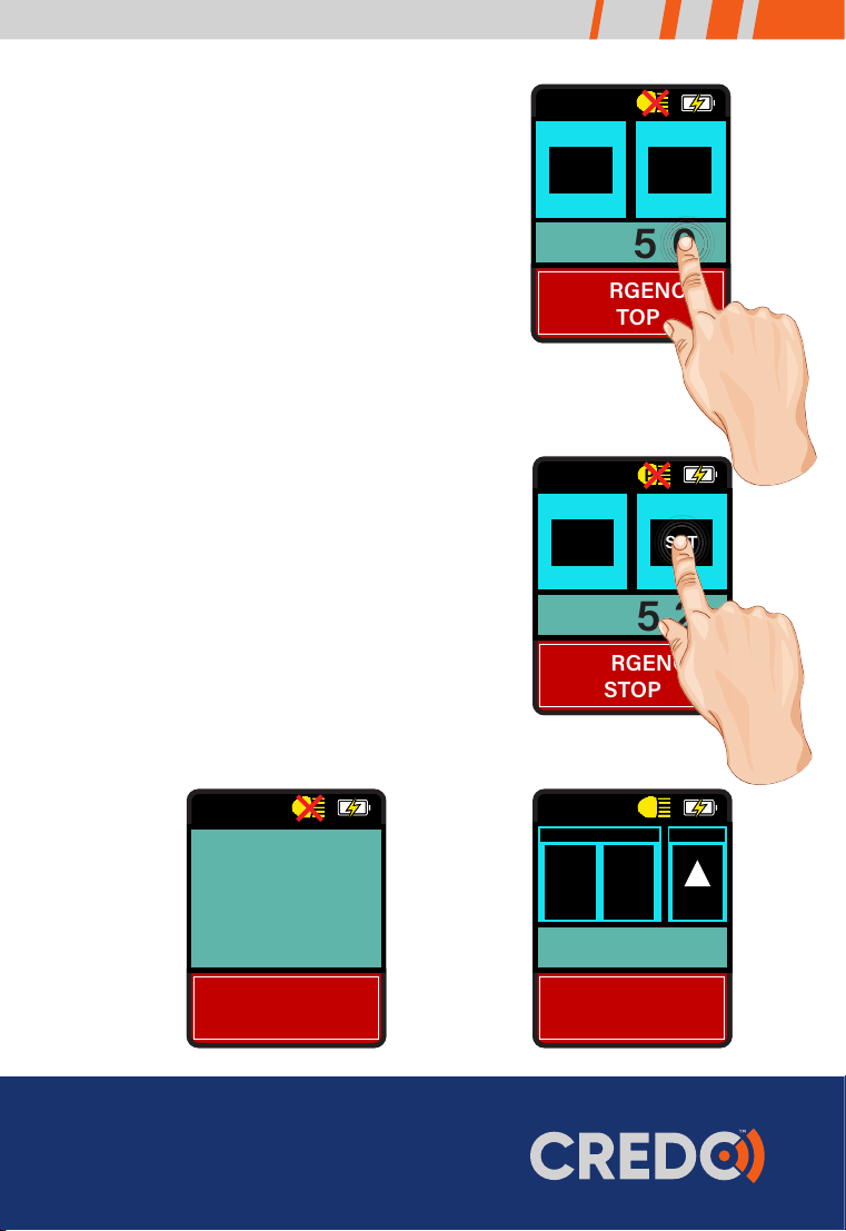
Recoding of Touch-Screen In-cab Controller
1Power up In-cab controller on the USB
cable and leave plugged in for the
duration of coding the controller.
2Wait till the screen displays the gain and
sensitivity control buttons.
3Press and hold the battery symbol for 5
seconds ignoring the screen flashing
any messages.
4The In-cab controller will do a single
beep and display 2 buttons ‘SET’ and
‘ESC’, and a 4 digit number. This number
is the number serial number of the
matching trailer mounted controller.
5Change the number by tapping each
digit to increment the digit by one.
To reach 0 increment the digit till it
reaches 9 and then the next tap brings
it back to 0. (Tip: tap lower on the
numbers to avoid bumping ESC or
SET).
-
-
EMERGENCY
STOP
LESS MORE ADJ.
+
GAIN SENS.
ZzP
1000
EMERGENCY
STOP
SET
ZzP
ESC
Refer to step 4
Refer to step 3
Refer to step 2
15
NZ Freephone 0800 487 245
E sales@trailparts.co.nz
www.trailparts.co.nz
6Once you have the serial number of
your trailer mounted controller showing
press ‘SET’ to lock the In-cab controller
to that serial number.
7The In-cab controller will after a pause
emit 3 beeps and return to the normal
operation screen.
8Connect the trailer to vehicle and turn
on the headlights – check the head light
symbol loses the red cross to prove it is
connected to the trailer and functioning
as normal.
9If red cross doesn't go away, unplug
In-cab controller and select immediate
sleep if this screen appears.
Leave unplugged for approx 5 seconds.
Plug in the In-cab controller and if the
serial number on the fourth start up
screen does not match the number on
the trailer, start recoding process again.
-
-
EMERGENCY
STOP
LESS MORE ADJ.
+
GAIN SENS.
ZzP
4350
EMERGENCY
STOP
SET
ZzP
ESC
4352
EMERGENCY
STOP
SET
ZzP
ESC
Fourth start up screen Refer to step 8
Refer to step 6
Refer to step 5
VERSION 1.9
SERIAL 1000
EMERGENCY
STOP
ZzP

16
AU Freephone 1300 538 598
E sales@trailparts.com.au
www.trailparts.com.au
Warranty Terms and Conditions
LIMITED EIGHTEEN MONTH WARRANTY CONDITIONS
Trailequip Ltd warrants that the mechanical and
electrical components of the TRAILPARTS/CREDO
products as listed below will be free of defects in
material and workmanship for a period of eighteen
months from the original date of purchase.
Whilst we take every eort to ensure compatibility
with all known vehicles we cannot guarantee 100%
compatibility for all vehicles.
To obtain any warranty service, you must provide
Trailequip Ltd with proof of purchase, such as a copy of
your tax invoice or purchase receipt, which will include
a purchase date and the serial number of your product.
This warranty does not cover the removal or re-fitting
of the product.
TRAILPARTS/CREDO will, at its discretion, repair,
replace or refund the purchase price of a defective
product or component, provided you return the
defective product or component during the warranty
period, freight charges prepaid, to Trailequip Ltd or to
an authorized TRAILPARTS/CREDO dealer or stockist.
Attach your name, address, email address, telephone
number, a description of the problem, and a copy of
the tax invoice or purchase receipt listing the date of
purchase and the TRAILPARTS/CREDO serial number
of the defective product.
This warranty does not apply if the product has been
damaged by misuse, overloading, impact, modification,
improper installation. This warranty is void if any
TRAILPARTS/CREDO serial number has been removed,
altered, or defaced.
Please contact the below for
warranty service or support:
TRAILPARTS/CREDO
C/ Trailequip Ltd
2 Tuna Street
Dargaville 0310
New Zealand
International Phone: +649 439 5508
Australia Phone: 1300 538 598
Check battery is keeping well charged. A well charged battery should be at or above 13 volts.
This is particularly important if the trailer is left parked for extended periods of time. If the trailer
is not used for extended periods the battery should be removed every 2 months and charged to
ensure it does not become damaged. This can happen if the battery charge drops below
10.5 volts.
Check the trailer plug and vehicle socket to ensure they are not damaged and they give a
sound electrical connection. An intermittent or faulty connection could mean the brakes do not
function correctly.
If fitted with a hydraulic actuator make sure the fluid level remains suicient. The fluid should be
changed in line with general trailer service intervals.
If fitted with electric drums make sure they are kept properly adjusted and that the magnets and
linings are not excessively worn and are replaced in line with general trailer service intervals.
Maintenance and checks

17
NZ Freephone 0800 487 245
E sales@trailparts.co.nz
www.trailparts.co.nz
Notes:

18
AU Freephone 1300 538 598
E sales@trailparts.com.au
www.trailparts.com.au
Notes:

19
NZ Freephone 0800 487 245
E sales@trailparts.co.nz
www.trailparts.co.nz
Notes:
AU Freephone 1300 538 598
E sales@trailparts.com.au
www.trailparts.com.au
NZ Freephone 0800 487 245
E sales@trailparts.co.nz
www.trailparts.co.nz
Other manuals for Credo
1
Table of contents


