Trak-Star 1" Gasoline Impact Wrench User manual

Serial #: Date:
operator’s manual
COVERS PART NUMBER 0012601
GASOLINE IMPACT WRENCH

1" Gasoline Impact Wrench
Welcome to Trak-Star®
Congratulations on your purchase of the Trak-Star®Gasoline Impact Wrench. Your model is designed to create
higher fastening torque quickly and efciently. Through constant innovation and development, Trak-Star®is
committed to provide you with tools and products that lead the industrial world.
Before attempting to operate your new Gasoline Impact Wrench, please read all instructions rst. These include
the Operators Manual and Warning Labels on the unit itself. With proper use, care, and maintenance, your model
will provide you with years of effective performance. Once again, thank you for selecting our product and
welcome to Trak-Star®.
SPECIFICATIONS
Engine...........................Two Stroke, Gas 46.5cc
Ignition...........................Electronic
Capacity.........................1-5/8" (41mm) Bolt Diameter
Net Weight.....................39.6 lbs. (18kgs) Without Fuel
Welcome to Trak-Star 2 Engine Breakdown & Parts List 13-15
Safety Instructions 3 Impact Unit & Gearbox Breakdown & Parts List 16-17
Technical Data 4-5 Ozat Sockets 18
Operating Instructions 6-7 Trak-Star Products 19
Trouble Shooting 8-9 Factory Authorized Warranty Repair Centers 20
Maintenance 10-12
2
0012601 - 1" Gasoline Impact Wrench
Read to fully understand and
observe the following safety
precautions and warnings. Careless
or improper use of tool may cause
serious or fatal injury.
WARNING! Indicates instant
possibility of severe personal
injury or loss of life, if instructions
are not followed.
Always wear eye, head and ear
protectors when using this tool.
SAFETY FIRST
InDeX
CAUTION! Indicates possibility
of personal injury or equipment
damage, if instructions are
not followed.

Work Area
Keep your work area clean and well lit. Cluttered benches and
dark areas invite accidents.
Do not operate power tools in explosive atmospheres, such as
in the presence of ammable liquids, gases or dust. Power tools
create sparks which many ignite the dust or fumes.
Keep bystanders, children, and visitors away while operating a
power tool. Distractions can cause you to loose control.
Operator Safety
• Always wear a safety face shield or goggles.
• Always wear heavy, long pants, boots and gloves. Do not wear
loose clothing, jewelry, short pants, sandals or go barefoot.
Secure hair so it is above shoulder length.
• Do not operate the tool when you are tired, ill or under the
inuence of alcohol, drugs or medication.
• Never let a child or inexperience person operate the machine.
• Wear hearing protection.
• Never start or run the engine inside a closed room or building.
Breathing exhaust fumes can kill.
• Keep handles free of oil and fuel.
• Keep hands away from anvil.
• Do not grab or hold the unit by rotating anvil.
• Hold the handles rmly with both hands and make sure to stand
on a rm base or ground.
• Do not touch spark plug or high voltage cord during operation
as it may cause electric shock.
• To avoid burn do not touch those places like engine, mufer
and exhaust. These parts get very hot during use, even after
engine is stopped.
• When operation is prolonged, take a break from time to time, so
that you may avoid possible whitenger disease. This is
caused by vibration.
Tool Safety
• Inspect the entire tool before each use. Replace damaged parts.
Check for fuel leaks and make sure all fasteners are in place and
securely fastened.
• Replace parts that are cracked, chipped or damaged in any way
before using the tool.
• Keep others away when making carburetor adjustments.
• Use only accessories as recommended for this tool by the
Manufacturer.
Fuel Safety
• Mix and pour fuel outdoors and where there are no sparks
or ames.
• Use a container approved for fuel.
• Do not smoke or allow smoking near fuel or the tool or
while using the tool.
• When lling up fuel, stop engine and make sure engine is cool
and choose a well ventillated place where no amables are
present. 3
IMPORTANT SAFETY INSTRUCTIONS
WARNING: Read and understand all instructions. Failure to follow all instructions listed below,
may result in electrical shock, re and/or serious personal injury.
• Wipe up all fuel spills before starting engine.
• Move at least 3m away from fueling site before starting engine.
• Stop engine before removing fuel cap.
• Empty the fuel tank before storing the tool. It is recommended
that the fuel be emptied after each use. If fuel is left in the tank,
store so fuel will not leak.
• Store tool and fuel in area where fuel vapors cannot reach
sparks or open ames from water heaters, electric motors,
switches and furnaces, etc.
Maintenance Safety
• Maintain the tool according to recommended procedures.
• Disconnect the spark plug before performing maintenance
except for carburetor adjustments.
• Keep others away when making carburetor adjustments.
Use only genuine replacement parts as recommended by
the manufacturer.
Transport and Storage
• Carry the tool by hand with the engine stopped and the
mufer away from your body.
• Allow the engine to cool, empty the fuel tank, and secure the
tool before storing or transporting in a vehicle.
• Empty the fuel tank before storing the tool. It is recommended
that the fuel be emptied after each use. If fuel is left in tank,
store so fuel will not leak.
• Store tool out of reach of children.
• Clean the unit carefully and store in a dry place.
• Make sure engine switch is off when transporting or storing.
If situations occur which are not covered in this manual, take
care and have a good judgement. Contact your dealer if you
need assistance.
Service
Tool service must be performed only by qualied repair
personnel. Service or maintenance performed by unqualied
personnel could result in a risk of injury.
When servicing a tool, use only identical replacement
parts. Follow instructions in the Maintenance section of
this manual. Use of unauthorized parts or failure to follow
maintenance instructions may create a risk of electric shock
or injury.
WARNING
Never modify the tool in any way. Do not
use your tool for any job except that for
which it is intended.
WARNING
Antivibration systems do not guarantee that
you will not sustain whitenger disease or
carpal tunnel syndrome. Therefore,
conitinual and regular users should monitor
closely the condition of their hands and
ngers. If any of the above symptoms
appear, seek medical advice immediately.

4
TECHNICAL DATA
INTRODUCTION
The Trak-Star Gasoline Engine Impact Wrench is a high quality tool with a self-contained, heavy duty,
high power two cycle engine. It’s unique design, combining an impact mechanism, pneumatic
B-Hammer and small high powered 46.5 cc gas engine, produces an ultra light-weight 39.6 lbs. (18kg),
impact wrench that can produce high fastening torque.
Because of the self-contained, high power two cycle engine, it is very easy to carry by one man to any
construction sites in the rain forest, hill, desert or remote areas where electricity supply, air compressor
or generator are not available.
The capacity of this tool is 1-5/8" (41mm) bolt size and is ideal for fastening and loosening bolts of
wood sleepers at railroad construction sites and many more applications.
ENGINE Type Two Stroke, Forced, Air Cooled, Single Cylinder
Displacement 46.5cc, 44x34mm (Inner bore size by stroke)
Fuel Tank Capacity 1 Liter
Fuel Mixture Ratio 25:1 (gasoline : 2 cycle oil)
Revolution (Idling) ≤ 2700 rpm; Engagement Speed: ≥ 3400
Revolution (Loaded, Impact) 7120 rpm
Revolution ( Non loaded, max) 8500 rpm
Maximum Output 2.03 Ps/6500 rpm
Maximum Torque 0.34 kg-m/5500 rpm
Compression Rate 7.4 : 1
Fuel Consumption Rate 520g/kWh
IGNITION Type Electronic
Spark Plug Type L8RTC
CARBURETOR Type Diaphragm
IMPACT Square Drive Size 1" (25.4mm)
Fastening Torque Range 550 - 1700 N.m (406 - 1250 ft. lbs.)
Free Speed 1200 rpm
CAPACITY Bolt Diameter 1-5/8" (41mm)
WEIGHT Without Fuel 39.6 lbs. (18kg)
OVERALL Length 25-1/2"
DIMENSIONS Height 10-3/4"
Width 15"
ACCESSORIES Hex Key Wrench 5mm (1 pc)
6mm (1 pc)
8mm (1 pc)
Spark Plug Wrench (1 pc)
Spanner 10 - 13mm (1 pc)
Sound Pressure Level (LPA,d) 101 dB (A)
Sound Power Level (LWA,d) 112 dB (A)
Vibrations (m/s2) 8.0 m/s2
Noise emission with and without load according to prEN ISO 15744. DECLARED SINGLE-NUMBER NOISE EMISSION VALUES in accordance with ISO 4871.
Vibration level is measured at the handle with load according to ISO8662-7 Declared vibration emission value accordance with EN 12096.
NOTE: To improve the performance, the specications are subject to change without notice.

GOING EVERYWHERE,
NO ELECTRICITY & NO AIR POWER REQUIRED
5
Important notICe
Read all Safety Instructions listed at the beginning of this Operators Manual before operating
the GASOLINE IMPACT WRENCH.
1. Carefully read the instructions before operating.
2. Use only sockets and adapters, which are in good condition and are intended for use with power tools.
3. Adopt a suitable posture to counteract unexpected movement of the power tool.
4. If using a suspension device, ensure that the power to is securely xed.
5. Release the start and stop device in the case of an interruption of the energy supply.
6. The operator should have enough strength to hold the tool stably when using the tool.
7. Use #10 lubricant, thick machine oil is not recommended.
FUEL
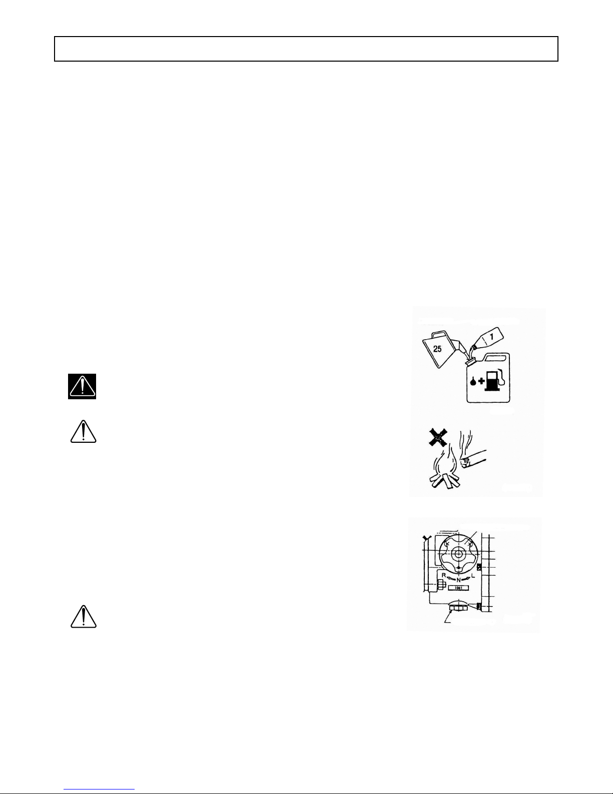
• Use only quality two cycle oil with gasoline at a mixture ratio of 25:1
(Gasoline : Two cycle oil) (Fig. 3)
• Never use gasoline only as engine will burn.
WARNING
Do not smoke and keep all other re away from the fuel tank during
lling fuel as it causes re it can burn yourself. (Fig. 3-1)
CAUTION
Wipe up all fuel spills before starting engine.
START UP ENGINE
1. Place the tool on a rm stand or solid oor.
2. Set gear change lever to neutral (N) position. (Fig. 3-2)
3. Slide stop switch to upward as shown. (Fig. 3-3)
4. Press priming bulb several times so that fuel slows through bulb
into carburetor. (Fig. 3-4)
5. Turn Choke lever to closed position. (Fig. 3-5)
6. Pull recoil starter handle strongly, taking care to keep the handle in
your grasp and not allow to withdraw rope until the end. (Fig.3-6)
CAUTION
Return recoil starter rope gently to its original position.
OPERATING INSTRUCTIONS
6
GASOLINE TWO CYCLE OIL
(FIG. 3)
(FIG. 3-1)
(FIG. 3-2)
OIL POT PORT
GEAR CHANGE LEVER
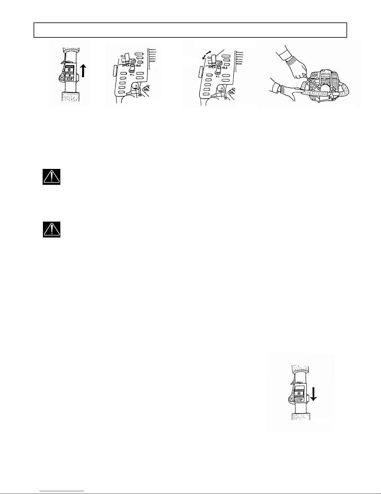
7. After initial re, engine will continue to run, return choke lever slowly to open position.
8. If engine stops after a few res by procedure (7), return choke lever to open position and pull recoil starter
handle strongly again.
9. If engine does not start by procedure (8), repeat procedures from (5).
10. After starting engine, return throttle lever to idle position for slow engine. Then allow the engine about 2-3
minutes to warm up before use. (Fig. 3-6).
WARNING
• Once engine is started, do not leave tool alone. Always hold handle tightly so that tool will not
move around on the stand or oor.
• Before and during operation, always take a rm stance and keep safety position from slipping or
falling down.
(FIG. 3-4)
PRIMING BULB
OPEN
(FIG. 3-5)
(FIG. 3-6)
CLOSED CHOKE LEVER
(FIG. 3-3)
WARNING
1. Power tools shall not be used in potentially explosive atmospheres unless specially designed
for that purpose.
2. Unexpected tool movement due to reaction forces or breakage of inserted tool may cause injuries.
3. Power tools shall be isolated from the energy source before changing or adjusting the
inserted tools.
4. Avoid the risk of being injured, keep hands away from the nut runner socket.
5. Avoid the danger to persons from high-speed splinters being emitted from impact wrenches
in the case of nut runner socket failure.
6. Unexpected direction of inserted tool movement can cause a hazardous situation.
7. Avoid inhaling the dust and ejected particles when operating the tool.
8. Continued use over prolonged periods of time can injure hands. If hands numb, ache or shows
white skin, operator should stop tool use and immediately seek medical attention.
OPERATING INSTRUCTIONS
6 7
OPERATION
1. Select R (for clockwise direction) or L (counter clockwise direction)
gear for fastening or loosening bolts and nuts.
2. Always release throttle lever to allow slow engine for idling and
turn gear change lever. DO NOT change gear when engine is accelerating.
3. Squeeze throttle lever for high speed to tighten or loosen bolts and nuts
and control engine speed with throttle lever.
4. Once bolts or nuts are fastened, release throttle lever for idling and not
allow driving shaft to turn. Remove socket from bolt of nut.
STOPPING ENGINE
1. Release throttle lever to decrease engine speed.
2. Return stop switch to stop position (Fig. 3-7)
3. Place the tool on rm stand or solid oor and turn gear change lever
to N (neutral) position.
(FIG. 3-7)

TROUBLE SHOOTING
89
SYMPTOM PROBABLE CAUSE CORRECTIVE ACTION
ENGINE DOES FUEL SYSTEM Fill up fuel at mixture ration 25 gal : 1 two cycle oil
NOT START • Empty fuel or shortage 1. Remove spark plug
• Wet spark plug due to too much
intake of fuel
2. Exhaust exceeded fuel by pulling recoil starter
handle 5-6 times
3. Install spark plug
4. Turn choke lever to open position and pull
recoil starter handle
• Bent or disconnection of fuel pipe Repair
• Poor function of carburetor • Air leak from carburetor
• Incorrect carburetor adjustment
• Bad diaphragm in carburetor
• Incorrect carburetor valve hinge height adjust.
ELECTRICAL SYSTEM
• Ignition stop switch in stop position Turn to "on" position
• No spark 1. Bad connection/Ignition coil
2. Incorrect air gap/Ignition coil
3. Bad ignition coil
• Short circuit of stop switch lead wire Repair or replace
• Dirty plug Clean up or replace
• Wider spark plug gap Adjust correct gap to 0.6mm
• Poor connection of high voltage cord
in ignition with spark plug
Correct connection
ENGINE WILL FUEL SYSTEM
STOP SOON • Shortage of fuel Fill up fuel at mixture ration 25 gal : 1 two cycle oil
AFTER STARTING • Choke lever in closed position Turn to "open" position
OR IS LIKELY • Air goes through to fuel system Check for cracks on pipe or connector and pipe
is securely xed.
TO STOP
• Poor function of carburetor • Air leak from carburetor
• Incorrect carburetor adjustment
• Bad diaphragm in carburetor
• Incorrect carburetor valve hinge height adjust.
ELECTRICAL SYSTEM
• Bad spark plug Replace
• Bad ignition coil Replace

9
TROUBLE SHOOTING
SYMPTOM PROBABLE CAUSE CORRECTIVE ACTION
ENGINE • Bad mixture ratio of fuel Fill up correct mixture ratio 25 gal : 1 two cycle oil
OVERHEATS • Wrong selection of spark plug Replace. Use pure and instructed parts only
• Clogged cylinder with dirt Clean up
• Clogged cooling duct with dirt Clean up
NON-REVOLUTION • Gear change lever in neutral Turn to R (clockwise direction) or L (counter
OF ANVIL SHAFT clockwise direction) position
• Worn out drum shoe on clutch arm Replace
OUTPUT POWER • Dirty air cleaner element Clean up
REDUCTION • Carbon deposits in mufer
exhaust port on cylinder
Clean up
• Poor cylinder pressure due to
worn piston, piston ring or cylinder
Replace
• Worn out Anvil Replace
• Worn out clutch Replace
• Worn out cam plate Replace
• Worn out hammer Replace
• Broken return spring Replace

MAINTENANCE INSTRUCTIONS
10
MAINTENANCE / CHECK-UP / REPAIRING
It is recommended to practice regular check-ups and maintenance in accordance with usage frequency to keep
your tool in its best condition and prolong life, reducing total running costs. This practice also protects you from
serious injury. Before maintenance, please release the start and stop device.
• Only use #10 lubricant, the tool should be lubricated at tool inlet.
• Do not replace the component or change the construction and design.
• If the component used is not the same as the original component supplied by the manufacturer,
the manufacturer shall not take responsibility.
• Keep the tool in a dry place when not in use.
DAILY CHECK-UP
• Check that all nuts and screws are securely tightened.
• Check fuel level. When lling up with fresh fuel, wipe up all spills and clean fuel tank.
• Check oil level of gear box through window. Oil level should be at the center of window. If lower than this
level, add oil.
WEEKLY MAINTENANCE
• Check the starter, especially the cord and return spring.
• Clean the exterior of the spark plug.
• Remove the spark plug and check the electrode gap. Adjust it to 0.6mm, or change the spark plug.
• Clean the cooling ns on the cylinder and check that the air intake at the starter is not clogged.
• Clean the air lter.
MONTHLY MAINTENANCE
• Rinse the fuel tank with gasoline.
• Clean the exterior of the carburetor and the space around it.
• Clean the fan and the space around it.
1. CARBURETOR ADJUSTMENT
1. When the engine is tested at the factory, the carburetor is properly adjusted.
Do not try to touch it.
2. When idle speed is higher or lower (engine will stop), adjust to correct speed
by idle adjustment screw. Turn clockwise for higher idle. Turn counter clock
wise for lower idle. (Fig. 5-1).
3. How to adjust the volume of inhaled oil (higher speed fuel adjustment)
Full open throttle lever, turn idle adjustment screw to right or left to look for the
peak idle speed. From this position, return adjustment screw to left 1/8-1/4 turn.
2. CHECK-UP SPARK CONDITION
1. Remove spark plug and touch it to metal part except spark plug mounting thread.
2. Pull recoil starter handle.
3. When in normal condition, you see a spark.
(FIG. 5-1)
VOLUME OF INHALED OIL
IDLE ADJUSTMENT SCREW
WARNING
Never touch spark plug to the area at spark plug mounting
thread since remaining gas might exploded.
WARNING
When pulling recoil starter handle, do not touch the metal part of
spark plug or you will get an electric shock.
Wipe and clean up fuel around spark plug area.
(FIG. 5-2)
REMOVE CARBON
0.6mm
11
MAINTENANCE INSTRUCTIONS
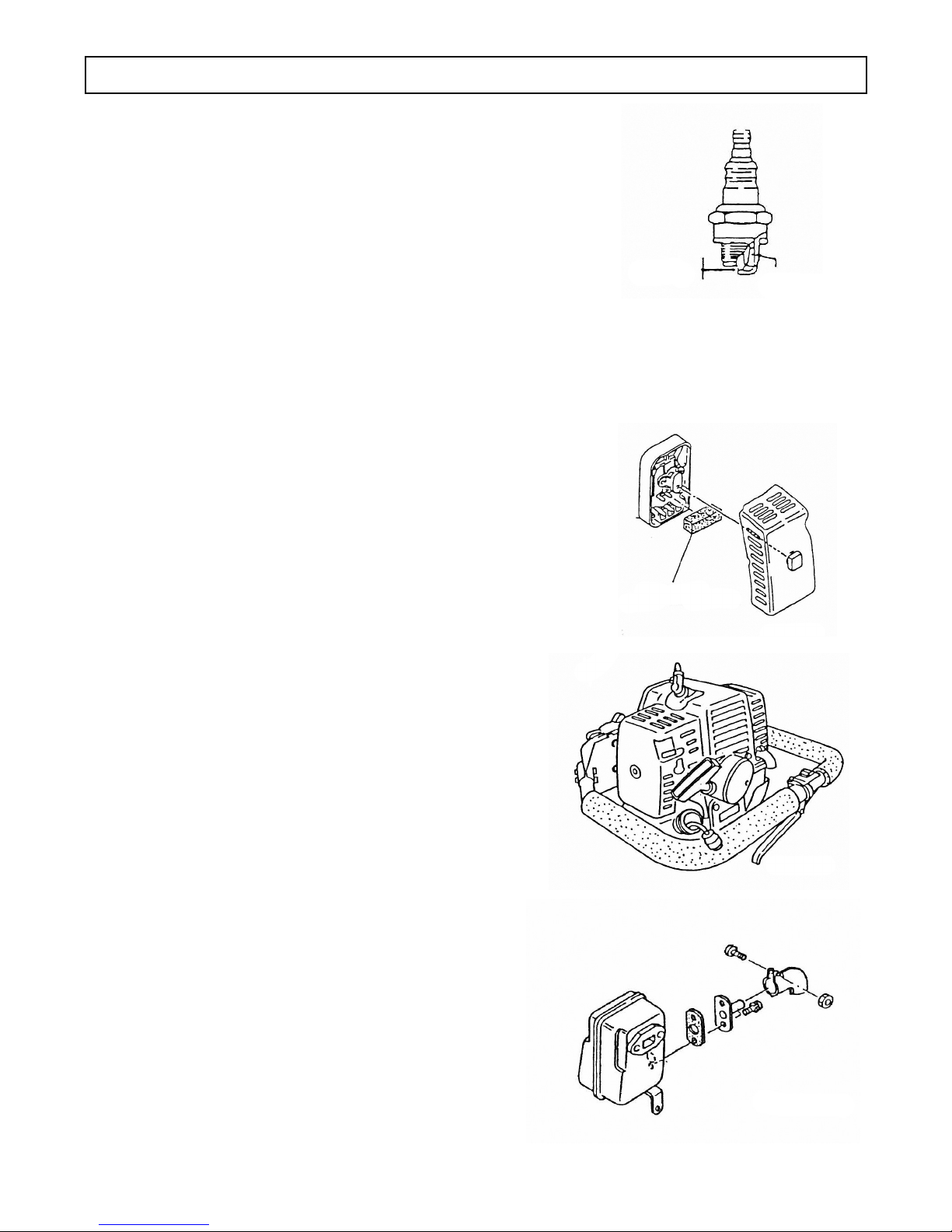
3. SPARK PLUG (Fig. 5-2)
1. Use only recommended type of spark plug.
2. In best operating condition, electrodes on the spark plug are dark brown.
Keep spark plugs dry. If the spark plug is dirty, clean it and check electrode gap.
If readjustment is necessary, the correct gap is 0.6mm.
The spark plug condition is inuenced by the following factors:
• An incorrect carburetor setting.
• Wrong fuel mixture (too much oil in gasoline).
• A dirty air lter.
• Hard running conditions (cold weather operations).
The spark plug should be replaced after 100 operation hours or earlier if the electrodes
are badly eroded.
4. AIR FILTER (FIG. 5-3)
1. When the air lter gets dirty and closed with dust, it will cause various troubles:
• Carburetor malfunctions.
• Starting problems.
• Engine power reduction.
• Unnecessary wear on engine parts.
• Abnormal fuel consumption.
2. Cleaning the air lter
Air lter must be cleaned from dust and dirt regularly and
damaged lter must be replaced with a new one.
• Remove the air lter cover and the lter.
• Rinse it in warm soapy water and wring tight. Let dry
before re-assembly.
• Damaged air lter must be replaced with a new one.
5. FUEL FILTER (Fig. 5-4)
1. If fuel lter is clogged with impurities in the fuel, fuel will
not ow into carburetor and it will make the engine
malfunction. Regular check-ups is recommended.
• Drain all fuel from fuel tank and pull out fuel lter
line from tank.
• Pull lter element out of holder assembly and rinse
element in warm water with detergent.
• Rinse thoroughly until all traces of detergent
are eliminated.
• Squeeze, but do not wring and let dry.
• If element is too dirty, replace.
6. MUFFLER (Fig. 5-5)
1. Engine power reduction might be caused by carbon
accumulation around the exhaust port on cylinder,
mufer inlet or outlet in the long use. Regular
clean-up is recommended.
• Remove the mufer and clean up any excess
carbon from the exhaust port or mufer inlet
every 100 hours of operation.
• When cleaning up, remove carbon carefully to not
damage piston. cylinder and do not let carbon into
crank case.
(FIG. 5-3)
AIR FILTER
(Cleaner Sponge)
(FIG. 5-4)
(FIG. 5-5)

12
MAINTENANCE INSTRUCTIONS
7. IMPACT MECHANISM
1. When contact places of anvil and hammer become worn-out by percussion, the tool becomes susceptible
to damage and can lead to breakage of parts.
• Empty all oil in the gear box and remove hammer housing completely and check the degree of
worn-out on anvil and hammer at least once every month. Grease around hitting area.
8. ADDING OIL
1. Use of the correct hydraulic oil is essential. Approved oils are Shell "TELLUS Oil" and Exxon
"TERESSTIC" (Part No. 75377). Grade #32 viscosity must be used. Check the unit specications. Make
sure that the work area and all equipment are clean so that no dirt, dust or other foreign material can get
into the hydraulic oil or pump area.
2. Remove Anvil plug (reference part no. 229 on page 16) and ll with #75377 Hydraulic oil.
3. Replace the Anvil plug and wipe up any excess oil.
9. STORAGE
1. Clean each part and apply two cycle oil on the metal part to prevent corrosion.
2. To keep tool for a long time (more than 3 weeks), drain fuel from fuel tank and keep running
engine without load until the engine will stop and exhaust all remaining fuel in the carburetor.
3. Remove spark plug and pure two cycle oil into cylinder and pull recoil starter handle several
times to spread oil.
4. Stop the recoil starter handle when you feel engagement.
5. Damaged parts should be repaired before storage.
6. Keep the tool in a place without dust or humidity, also the temperature below 50˚ C.
7. Store tool out of reach of children.
8. Keep fuel in safety container in a cool room or place where not ammable. Do not use
stale fuel as it cause engines troubles.
13
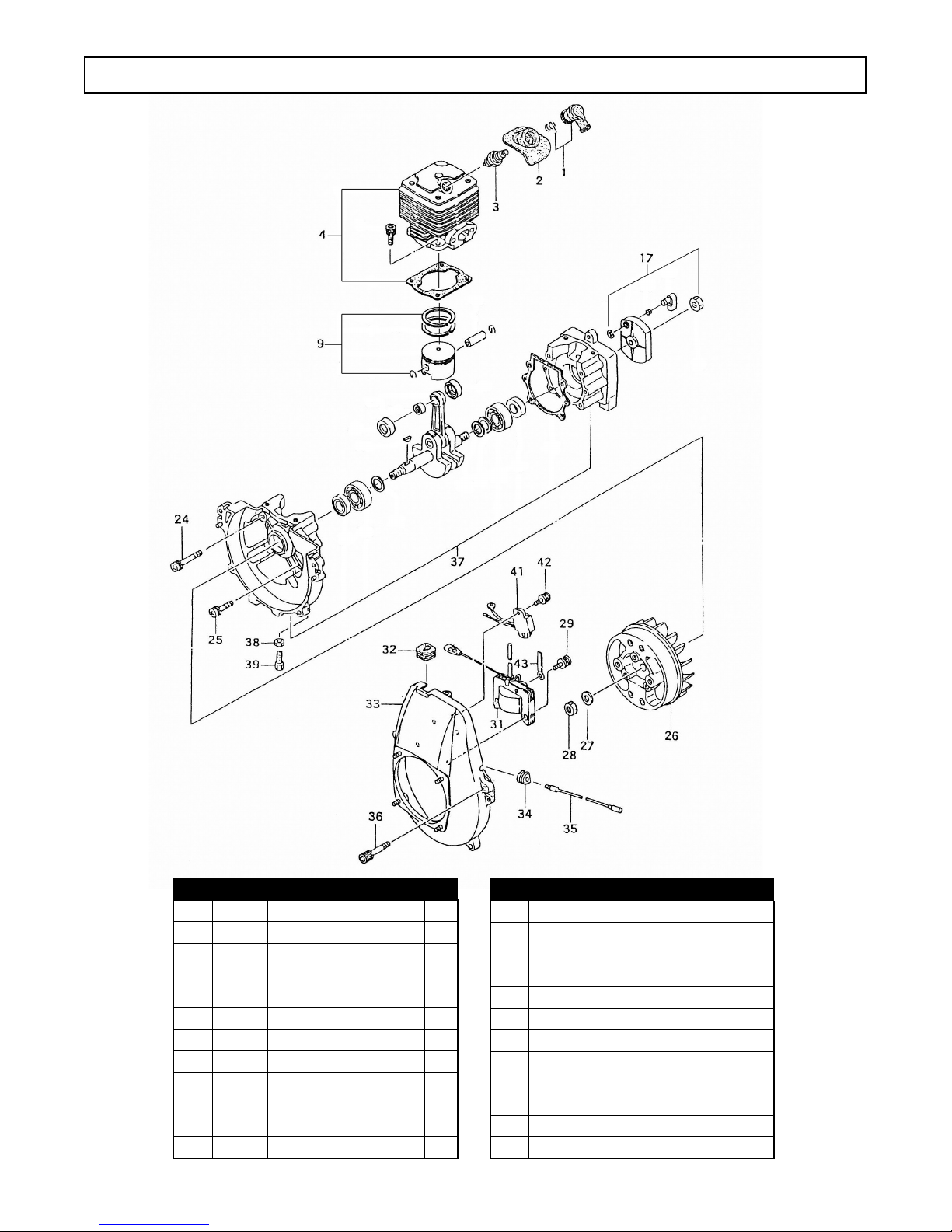
Item Part # Description Qty
107615 Spark Plug Ass’y 1
2 07616 Spark Plug Rubber Cover 1
3 07617 Spark Plug BPMR6A 1
4 07618 Cylinder Set 1
9 07619 Piston Set 1
17 07620 Starter Pulley 1
24 07726 Screw 6x45/S 2
25 07727 Screw 6x30 2
26 07621 Magnet Rotor Complete 1
27 07728 Small Washer .10 1
28 07729 Nut 10 1
29 07746 Screw 5x18/WS 3
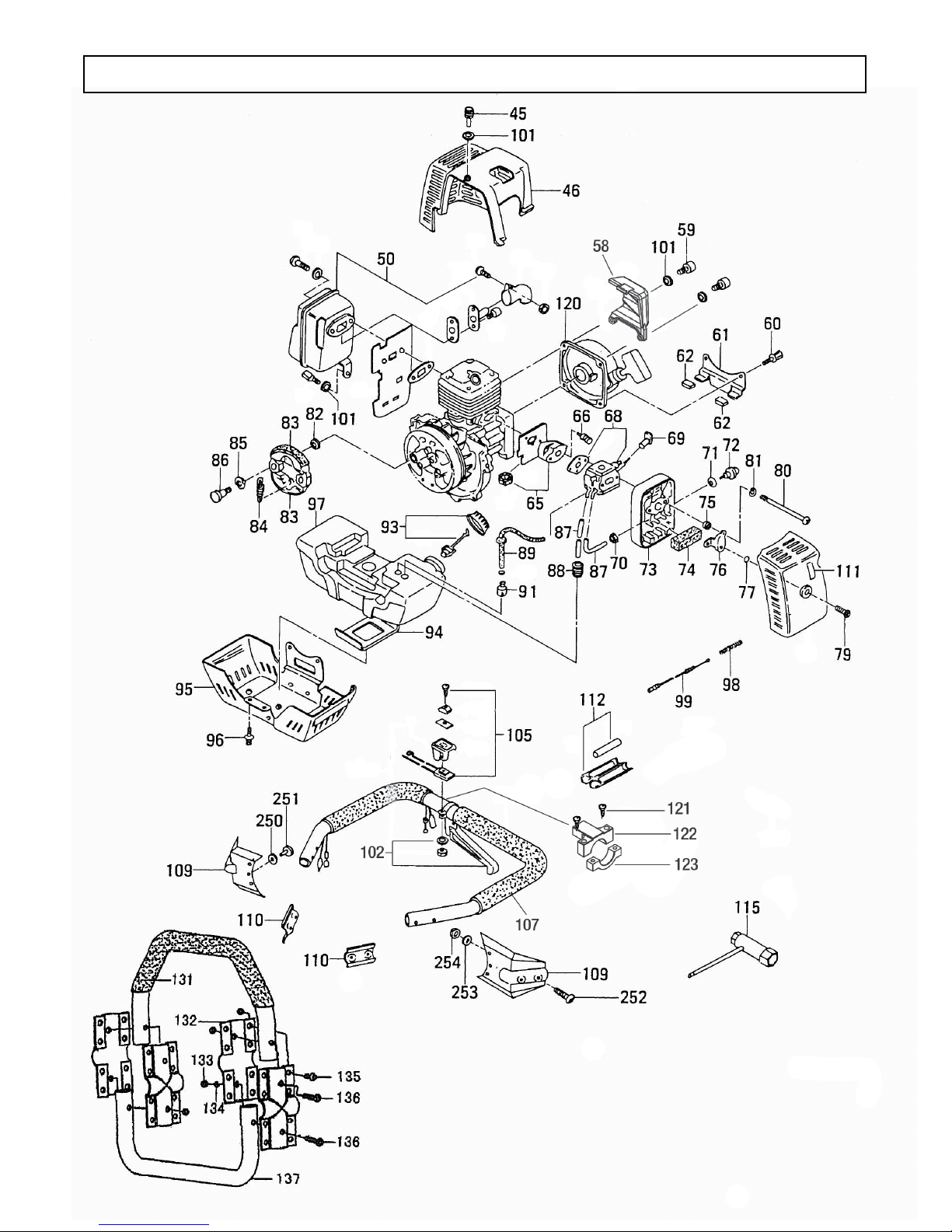
ENGINE - EXPLODED VIEW
Item Part # Description Qty
31 07622 Ignition Coil Complete 1
32 07623 Primary Cord Grommet 1
33 07624 Fan Case Complete 1
34 07625 Primary Cord Grommet 1
35 07626 Stop Cord Complete 1
36 07731 Hex Bolt 6x20/S 4
37 07627 Crank Case Ass’y 1
38 07747 Nut 6 1
39 07628 Outer Receiver 1
41 07629 Ignitor Complete 1
42 07730 Screw 5x14/PS 2
43 07630 Cord Clamp Complete 1
14
ENGINE COMPONENTS - EXPLODED VIEW

15
ENGINE COMPONENTS - PARTS LIST
Item Part # Description Qty
45 07748 Hex Bolt 1
46 07631 Mufer Protector 1
50 07632 Mufer Set 1
58 07603 Motor Vent Guard 1
59 05534 Hex Hole Bolt 2
60 07749 Hex Hole Bolt 1
61 07633 Tank Bracket 1
62 07634 Fuel Tank Cushion Rubber 2
65 07635 Carb. Insulator Set 1
66 07750 Hex Hole Bolt 2
68 07636 Carburetor Set 1
69 07637 Choke Lever 1
70 07733 Nut 1
71 07732 Inner Tooth Washer 1
72 07638 Priming Pump Complete 1
73 07639 Cleaner Body 1
74 07640 Cleaner Sponge 1
75 07641 Collar 2
76 07642 Blow Over Check Board 1
77 07643 O-ring 1
79 07644 Cleaner Cover Bolt 1
80 07751 Screw 2
81 07752 S. Washer 2
82 07645 Clutch Washer 2
83 07646 Clutch Arm Complete 2
84 07647 Clutch Spring 1
85 07753 Wave Washer 2
86 07648 Clutch Step Bolt 2
87 07649 Fuel Pipe 2
88 07650 Return Grommet 1
89 07651 Fuel Pipe Ass’y 1
91 07652 Pump Filter Body Ass’y 1
Item Part # Description Qty
93 07653 Tank Cap D Ass’y 1
94 07654 Cushion Rubber 1
95 07655 Tank Holding Metal Complete 1
96 07754 Hex Hole Bolt 2
97 07656 Fuel Tank, Vermilion 1
98 07657 Adjust Spring 1
99 07658 Throttle Wire Complete 1
101 07442 Washer 2
102 07614 Adjust Lever Ass’y 1
105 07660 Stop Switch Ass’y 1
107 07661 Handle Ass’y 1
109 07662 Handle Bracket 2
110 07663 Handle Holder 2
111 07664 Choke Mark 1
112 07665 Connector Case Ass’y 1
115 07666 Combi. Box Spanner 10x19 1
120 07667 Recoil Starter Body Ass’y 1
121 10558 SCR-BHC 10-32x1 2
122 07601 Guard - Switch 1
123 07600 Guard - Strap 1
131 07668 Auto-vibration Rubber 1
132 07669 Four Sides Handle Holder 4
133 07756 U-nut M6 20
134 07757 Washer Spring M6 20
135 07758 Hex Cap Bolt 16
136 07759 Hex Cap Bolt 4
137 07599 Kickstand 1
250 07767 Washer, Spring 6
251 07772 Hex Cap Bolt 6
252 07759 Hex Cap Bolt 4
253 07744 Washer, Jagged Spring 4
254 07756 U-nut 4
16
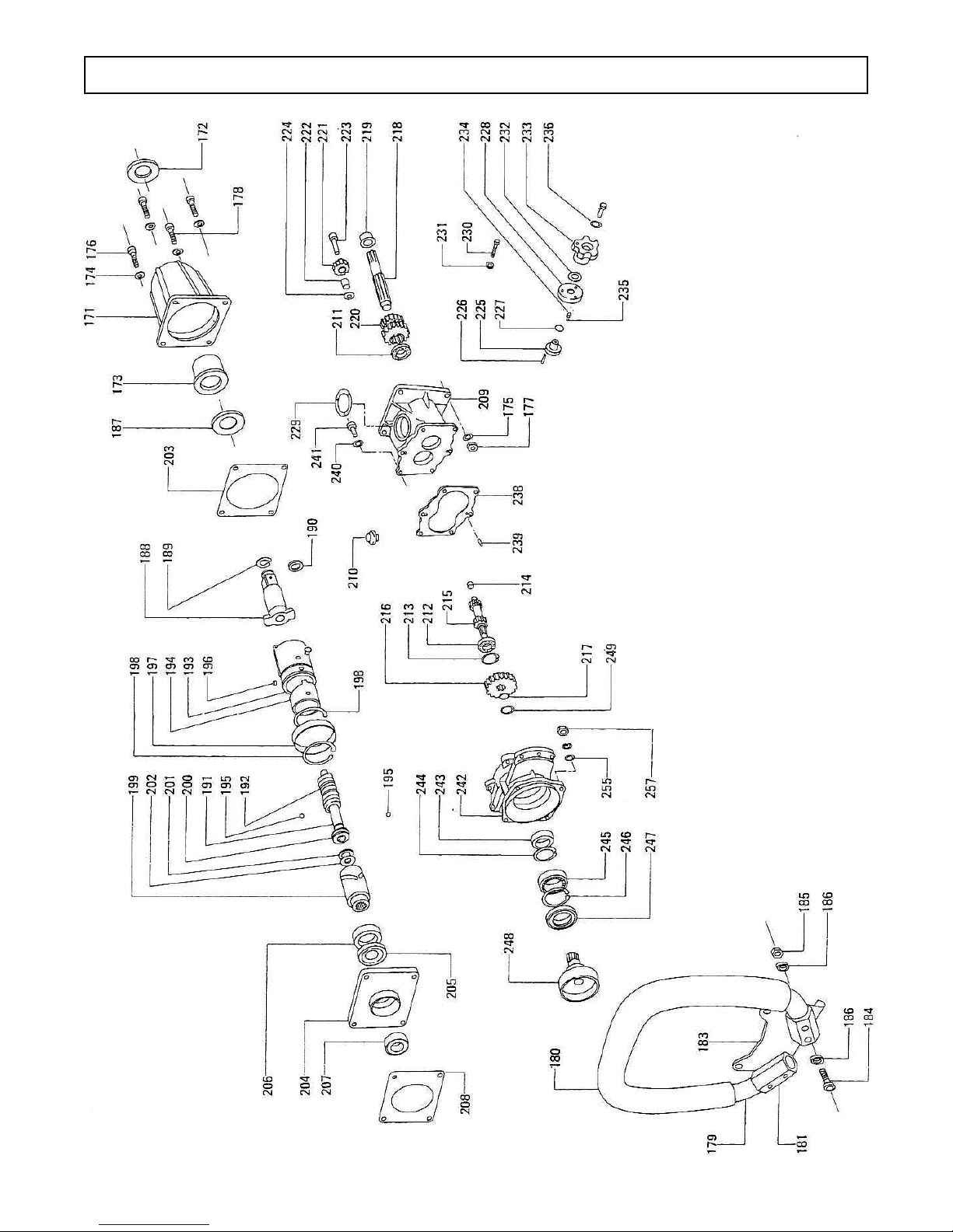
IMPACT UNIT & GEARBOX - EXPLODED VIEW

16 17
IMPACT UNIT & GEARBOX - PARTS LIST
Item Part # Description Qty
171 07671 Hammer Housing Complete 1
172 07672 Oil Seal 1
173 07673 Bushing 1
174 07760 Washer 2H-M8, Jagged Spring 4
175 07761 Washer M8, Spring 3
176 07762 Hex Cap Bolt 3
177 07763 U-nut M8, Hammer Housing 3
178 07764 Hex Cap Bolt M8x50 1
179 07674 Anti-vibration Handle Complete 1
180 07675 Anti-vibration Rubber 1
181 07676 Retainer, Anti-vibration Handle 2
183 07677 Foot Rest 1
184 07765 Hex Cap Bolt M6x45 4
185 07766 U-nut M6, Anti-vibration Handle 4
186 07767 Washer M6, Spring 8
187 07735 Washer, Thrust 1
188 07678 Anvil Complete 1
189 07736 Ring, Retainer 1
190 07679 O-ring P18, Retainer Ring 1
191 07680 Central Shaft 1
192 07681 Spring, Return 1
193 07682 Hammer Complete 1
194 07683 Cam Plate 1
195 07684 Roller Ball 13/32 2
196 07685 Plug 4
197 07686 Ring 1
198 07737 Snap Ring WR73 2
199 07687 Clutch 1
Item Part # Description Qty
228 07714 Gear Flange 1
229 07715 Packing, Gear Flange 1
230 07768 Hex Cap Bolt M5x10 3
231 07743 Washer 2H-M5, Jagged Spring 3
232 07745 Washer WW-16, Spring 1
233 07716 Lever, Gear Change 1
234 07717 Retainer Spring S3.8x7x0.6x6 1
235 07718 Steel Ball 4 1
236 07769 Washer M6, Spring 1
238 07719 Gasket, Gear Case 1
239 07720 Pin 4x13.8 2
240 07770 Washer 2H-M6, Jagged Spring 6
241 07771 Hex Cap Bolt M6x25 6
242 07721 Clutch Support, Flange Comp 1
243 07722 Ball Bearing 16005 1
244 07741 Snap Ring IRTW-47 1
245 07723 Ball Bearing 6907 1
246 07742 Snap Ring IRTW-55 1
247 07724 Oil Seal 1
248 07725 Clutch Ring 1
249 07740 Snap Ring STW-25 1
250 07767 Washer, Spring 6
251 07772 Hex Cap Bolt M6x12 6
253 07744 Washer 2H-M6, Jagged Spring 4
255 07773 Washer 2H-M6, Jagged Spring 4
257 07774 Screw M6 4
Item Part # Description Qty
200 07688 Bearing, Thrust 1
201 07689 Spacer 1
202 07690 Thrust 1
203 07691 Gasket, Hammer Housing 1
204 07692 Ring Flange Complete 1
205 07693 Oil Seal 1
206 07694 Ball Bearing 6007VV 1
207 07695 Ball Bearing 6006 1
208 07696 Gasket, Ring Flange 1
209 07697 Gear Case Complete 1
210 07698 Oil Pot Port PF3/8-19 1
211 07699 Ball Bearing 16004 1
212 07700 Ball Bearing 16003 1
213 07738 Snap Ring IRTW-35 1
214 07701 Bushing, Selector Shaft 1
215 07702 Shaft, Selector 1
216 07703 Gear 1
217 07739 Snap Ring STW-16 1
218 07704 Shaft, Bearing Complete 1
219 07705 Bushing, Bearing Shaft 1
220 07706 Gear Cluster 1
221 07707 Planetary Gear Complete 1
222 07708 Bushing, Planetary Gear 1
223 07709 Planetary Pivot 1
224 07710 Planetary Spacer 1
225 07711 Gear Selector Complete 1
226 07712 Spiral Pin 5x26, Gear Selector 1
227 07713 O-ring N14, Gear Selector 1

18
OZAT SOCKETS
Trak-Star now sells OZAT 8 point Impact Sockets. OZAT sockets are
superior to other sockets on the market because of their less-stress™
socket conguration. Each socket is made with a state of the art
electro-chemical machining process. OZAT sockets will result in longer
socket and fastener life.
Part No. Description
07100 1-1/4" OZAT socket
07101 1-5/16" OZAT socket
07102 1-3/8" OZAT socket
07103 1-7/16" OZAT socket
07104
1-1/2"
OZAT socket
07105
1-9/16"
OZAT socket
07106 1-5/8" OZAT socket
07107 1-11/16" OZAT socket
07108
1-3/4
OZAT socket
07109 1-13/16" OZAT socket
Order Today: 866-245-3745
3001 Hougen Dr • Swartz Creek, MI 48473
866-245-3745 • www.trak-star.com
Warranty
The Trak-Star warranty provides free replacement, to the original
purchaser, of any qualifying socket found to defective in either
workmanship, as indicated by breakage or premature wear.
Determination of free replacement will be made after an
examination by Trak-Star. Impact sockets, by their application,
are subject to extreme stresses. Products returned to Trak-Star
for warranty consideration must be shipped prepaid, with a
Trak-Star returned goods authorization (RGA) number issued
by the customer service department.
Part No. Description
07110
1-7/8"
OZAT socket
07111 2" OZAT socket
07112
2-1/8"
OZAT socket
07113 2-3/16" OZAT socket
07114 2-1/4" OZAT socket
07115 2-3/8" OZAT socket
07116 2-1/2" OZAT socket
07117 Retaining O-Ring
07118 Retaining Pin

19
Model RB28
Portable Gas Rail Drill
Portable Gas Bonding Drill
Model RB30
Power Feed Hydraulic Drill
Model RM42
OTHER PRODUCTS OFFERED BY TRAK-STAR
Modern, high speed railways and welded rails call for modern, high precision rail equipment.
Through our continual commitment, we now offer additional products that will be beneficial to
your specific applications.
Model BD17
Electric Bonding Drill
OTHER PRODUCTS OFFERED BY TRAK-STAR
Modern, high speed railways and welded rails call for modern, high precision rail equipment.
Through our continual commitment, we now offer additional products that will be benecial
to your specic applications.

1124
Hougen Manufacturing, Inc.
P.O. Box 2005 • Flint, MI 48501-2005
3001 Hougen Drive • Swartz Creek, MI 48473
Phone: (866) 245-3745 • Fax (800) 309-3299
E-Mail: info@trak-star.com
On-line: www.trak-star.com
OMIW0812 Printed in U.S.A.
© 2012 Hougen Manufacturing, Inc.
Hougen Manufacturing has received the
Association of American Railroads
Quality Assurance Program Certication
Hougen Manufacturing, Incorporated warrants its Trak-Star Rail Drills, Portable Magnetic Drills,
Electro-hydraulic Hole Punchers for one (1) year and other products for ninety (90) days from date of
purchase against defects due to faulty material or workmanship and will repair or replace (at its option) without
charge on any items returned. This warranty is void if the item has been damaged by accident or unreason-
able use, neglect, improper service, or other causes not arising out of defects in material or workmanship. No
other expressed warranty is given or authorized. Hougen Manufacturing, Inc., disclaims any implied warranty
of MERCHANTABILITY or FITNESS for any period beyond the expressed warranty and shall not be liable
for incidental or consequential damages. Some states do not allow exclusions of incidental or consequential
damages or limitation on how long an implied warranty lasts and, if the law of such a state governs your
purchase, the above exclusion and limitation may not apply to you. This warranty gives you specic legal
rights and you may also have other rights which vary from state to state.
To obtain warranty service, return the item(s), transportation prepaid, to your nearest Factory Authorized
Repair Center or to Hougen Manufacturing, Inc. 3001 Hougen Drive, Swartz Creek, Michigan 48473.
THIS WARRANTY IS IN LIEU OF ANY OTHER WARRANTY, EXPRESSED OR IMPLIED, INCLUDING ANY
WARRANTY OF MERCHANTABILITY OR FITNESS FOR A PARTICULAR PURPOSE.
© 2012 Hougen Manufacturing, Inc.
Commercial / Industrial Limited Warranty
Hougen Manufacturing, Inc. Kenbil Service Co.
3001 Hougen Drive 2900 Adams Street B-14
Swartz Creek, MI 48473 Riverside, CA 92504
(866) 245-3745 (951) 689-6633
Photographs and Specications shown are accurate in detail at time of printing. Manufacture reserves the
right to make improvements and modications without prior notice.
Hougen, Hougen-Edge, Trak-Star, and Punch-Pro are propriety trademarks of Hougen
Manufacturing, Inc. Ogura and the Ogura logo are proprietary trademarks of Ogura & Co., Ltd. Honda logo
appears courtesy of American Honda Motor Co.
FACTORY AUTHORIZED WARRANTY REPAIR CENTERS
This manual suits for next models
1
Table of contents
Popular Impact Driver manuals by other brands


Hitachi
Hitachi WH14DBL Handling instructions

Surtek
Surtek PI701 User's Manual and Warrantly

Ingersoll-Rand
Ingersoll-Rand 2135Qi Product information

Panasonic
Panasonic EY75A7 operating instructions

Metabo HPT
Metabo HPT WR 22SE Instruction manual and safety instructions

Ingersoll-Rand
Ingersoll-Rand 2141 instruction manual