TRAMPA VESC EXPRESS User manual

Manual

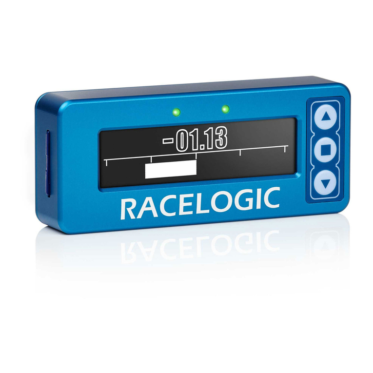
Congratulations on your purchase of your VESC Express dongle and logger module. This device features
an ESP32 module with Wi-Fi® speed connectivity, USB-C and a micro SD card slot to enable constant
logging while the VESC speed controller is powered (Micro SD card required). A GPS module can be added
for position and time/date logging. This will be a quick guide on how to install the VESC-Express,
configure it and view your log files.
If you are familiar with beta firmware then please
make sure you are on the latest version and start at 4
1. Wiring diagram/SD card installation
2. Firmware download
3. Firmware installation
4. Logging setup
5. How to view your logs
6. Wi-Fi® setup
7. Useful information
Contents
Should you have any problems with your VESC express dongle please contact Trampa Support
support@trampaboards.com

1. Wiring diagram
SD card installation

2. Firmware download
The VESC Express is very new and needs to use BETA FIRMWARE until VESC-Tool 6 is released.
The release of VESC-Tool 6 is not very far. We expect it to happen in December 2022.
The VESC express will already have the correct firmware installed but will only work in conjunction with
firmware updated VESC devices. Devices carrying older firmware will NOT support the VESC-Express!
This is a quick walk through of how to download the beta version of VESC-Tool.
Firstly, you will need to go to https://vesc-project.com/ and make sure you log into your account. If
you don’t have an account please register and purchase any VESC-Tool version.
Once logged in, menu options will appear in the top right corner. Click on PURCHASED FILES to access
the beta download link. NOTE if you have not downloaded the VESC-Tool, the beta link will not be
shown. Download the released version and then check back in PURCHASED FILES.
The Beta link will have all device versions in a .rar file. Please make sure you have software installed
to read and unpack the files. E.g. Winrar, Winzip, etc
Pick your desired version, click extract,
and choose a folder. There is always a
file with the build date, use this for
reference as the beta usually updates
once a week. Make sure to keep up to
date until there is an update for the
released VESC-Tool to Version 6.

Now go to the beta VESC tool and open it up. You will get a pop up when you open it, warning you that
this is a test version of the VESC tool. Click OK to continue. Then click AUTO CONNECT, don’t worry if
the VESC device takes a while to connect. This is because it is on old firmware. Once connection is
established you will see a pop up telling you the device is on old firmware.
Click OK to continue. Now navigate to the firmware tab on the left.
Click on the upload arrow to start flashing. This will take around 30 seconds then the VESC controller
will reset on its own. DO NOT POWER OFF!
When the VESC controller reboots you should get the warning message above. Click OK then navigate to
WLECOME AND WIZARDS and auto connect. NOTE If it you get the same ‘old firmware’ pop up then the
firmware hasn’t loaded correctly. If so, go back to the firmware tab and click BOOTLOADER tab at the
top. Click the upload arrow to flash the bootloader, then go back to the firmware tab at the top and
3. Firmware installation

4. Logging setup
The VESC express has the ability to log continuously while the VESC controller is powered. This is a big
step for logging as before you could only log data from the VESC device you were connected to. Now,
the VESC-Express will be able to log every VESC device and BMS connected to CAN.
Start by installing an SD card (installation guide on page 1). The size of the SD card would depend on
your project and how long you are logging for. More CAN devices and longer logs will result in large files.
Now the card is installed, power on your VESC speed controller and connect to the VESC-Tool. If you
have connected to the VESC-Express dongle then make sure you connect to your VESC speed controller
in CAN-devices (1). Once VESC speed controller is selected click on the VESC packages tab (2).
Now click yes and you will be shown the Log User Interface. The UI is easy to use, simply check the box
of the values you wish to record, and click START. More detailed info can be found under
VESC Package > LogUI.Please note that the permanent logging upon system start, incorporating GNSS
position data will start once a sufficient number of satellites are found.
Click on LogUI (3), and information will appear on the right hand side. Please read this carefully
as it explains what the logUI does and how to use its UI. Finally, click install to write the logUI package
to your VESC speed controller. Once installed you should see a pop up like below. Click OK then power
off the VESC speed controller and power it back on.
When reconnected, and the VESC speed controller is
selected on CAN (1), you will see a pop up asking you
to loadthe logUI. If you do not see a pop then the
installation has failed, make sure the VESC speed
controller is selected on CAN and retry the
installation.
1
2
3
4

5. How to find your logs
When you want to view a log file you will need to connect your VESC device to the desktop version of
VESC-Tool (Windows/Linux/macOS). Once connected make sure to select the VESC Express dongle in
CAN-devices (1), select Log analysis (2), make sure BROWSE and CONNECTED DEVICE are selected (3),
now press refresh (4).
You should now see a folder called “log_can”. In here there will be a folder called “date” or “no_date”.
If you record GNSS position data it will pick up time and date and save in the “date” folder. No_date is
data without GNSS information (GNSS data logging deactivated or no GPS Module intsalled)
1
2
3
4

Select a file and click open. If you have recorded GNSS data plot points will show on the map where the
data was recorded. When the files have loaded click on the Data tab to view.
In the data tab you will need to click on a value for it to show(1). You can select multiple values. Click
on the graph to move a slider (2) and accurately read the data at each plot point. If GNSS was recorded
the plot points will move with this slider to show you exactly where the piece of data you are viewing
occurred (3).
1
2
3

6. Wi-Fi® setup
To setup Wi-Fi®, first have your VESC-Express connected to your VESC speed controller and power on.
Then, connect to the VESC-Tool and click SCAN CAN (1). When the VESC-Express shows up, click on it to
connect (2). Once connected you should see VESC EXPRESS tab on the left (3), click here to access
settings for the device. Click the Wi-Fi® tab at the top for Wi-Fi® settings (4).
The Wi-Fi® on the VESC-Express has 2 modes, Station mode and Access point. Station mode will connect
to your router at home (access through any device with the VESC-Tool connected to WLAN/LAN) and
Access point will generate a Wi-Fi® Hotspot you can connect to.
Station mode requires you to enter your router SSID and Wi-Fi® password, these are usually found on a
sticker on the router. Once this is entered into the VESC-Express settings you should make sure Wi-Fi®
mode is set to ‘Station mode’ and then click write to save (5).
Access point only requires you to select Wi-Fi® mode ‘Access point’ and then click write to save (5)
You can change the SSID and password to whatever you like but remember to write to save the setting.
Once access point is active go to Wi-Fi® settings on your device and look for the access point SSID. Once
found click connect and enter your chosen password. Once connected open the VESC-Tool.
Wether you have connected via your router
(station mode) or via the express wifi
(access point), you should see the express
dongle pop up when you open the vesc tool.
Right is an example of what it would look
like.
1
25
3
4

7. Useful Information
Videos
Log rate
The log rate is limited by the CAN-Speed. For example, at 500k baud you can send around 1000
can-frames per second. If you then have one extra VESC device that sends status 1-5 at 50 Hz
you have 1000 - 50*5 = 750 frames/second left. Two fields in the log require one can-frame,
if you want to log 20 values you get a maximum rate of (1000 - 50 * 5) / (20 / 2) = 75 Hz.
It is wise to use a lower rate, not maxing out the CAN bandwidth. A lower log rate also greatly
reduces files size! The default value is 5 to 10Hz.
Benjamin Vedder has done some demo/explanation videos on the VESC Express dongle. Please see
below for channel link and relevant video links:
VESC Express Demo
https://www.youtube.com/watch?v=wPzdzcfRJ38&ab_channel=BenjaminVedder
Adjust log fields
The log fields can be adjusted easily in the VESC-Tool. With the device connected, go to VESC
Dev Tools, select the Lisp tab, then click “read existing”. This will display all fields recorded on
the local VESC device, devices on CAN and BMS. Once you have edited the code to the fields you
require, click upload to load your custom logging code to the VESC speed controller.
Should you have any problems with your VESC express dongle please contact Trampa Support
support@trampaboards.com
Introduction to VESC Packages
https://www.youtube.com/watch?v=R5OrEKK5T5Q&ab_channel=BenjaminVedder
Benjamin Vedder’s Channel
https://www.youtube.com/@BenjaminsRobotics
Table of contents
