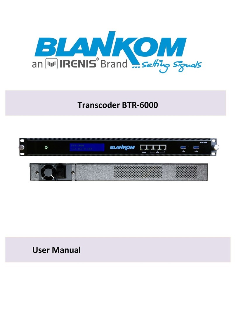
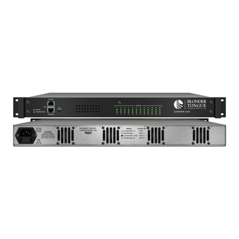
TransLite TL-A1000 User manual

P a g e | 1
DISCLAIMER
No part of this document may be reproduced in any form without the written permission of the copyright
owner.
The contents of this document are subject to revision without notice due to continued progress in
methodology, design and manufacturing. TRANSLITE GLOBAL LLC shall have no liability for any error or
damage of any kind resulting from the use of this document.
COPY WARNING
This document includes some confidential information. Its usage is limited to the owners of the
product that it is relevant to. It cannot be copied, modified, or translated in another language
without prior written authorization from TRANSLITE GLOBAL LLC
PRODUCT MODEL NUMBER: TL-A1000 LIVE
STREAMING TRANSCODER
ABOUT THIS MANUAL

P a g e | 2
INDEX
TABLE OF CONTENTS
CHAPTER 1 INTRODUCTION ...................................................................................................................3
1.1 PRODUCT OVERVIEW........................................................................................................................3
1.2 KEY FEATURES...................................................................................................................................3
1.3 SPECIFICATIONS................................................................................................................................6
1.4 PRINCIPLE CHART.............................................................................................................................7
1.5 APPEARANCE AND DESCRIPTION......................................................................................................8
CHAPTER 2 INSTALLATION GUIDE...........................................................................................................9
2.1 ACQUISITION CHECK.........................................................................................................................9
2.2 INSTALLATION PREPARATION ............................................................................................................9
2.3 DEVICE’S INSTALLATION FLOWCHART.............................................................................................. 10
2.4 ENVIRONMENT REQUIREMENT....................................................................................................... 10
2.5 GROUNDING REQUIREMENT........................................................................................................... 11
2.5.1 FRAME GROUNDING.................................................................................................................... 11
2.5.2 DEVICE GROUNDING.................................................................................................................... 11
2.6 WIRE’S CONNECTION...................................................................................................................... 12
2.7 SIGNAL CABLE CONNECTION........................................................................................................... 12
CHAPTER 3 DEVICE ACCESS AND LOGIN ...............................................................................................12
3.1 LOGIN ............................................................................................................................................13
CHAPTER 4 DEVICE MANAGEMENT...................................................................................................... 14
4.1 HOST MANAGEMENT ..................................................................................................................... 14
4.2 CAPTURE MANAGEMENT................................................................................................................17
4.3 CHANNEL MANAGEMENT............................................................................................................... 18
4.4 PARAMETER TEMPLATE ..................................................................................................................19
4.5 ALARM LOGS..................................................................................................................................23
CHAPTER 5 TASK MANAGEMENT ......................................................................................................... 24
CHAPTER 6 SYSTEM MANAGEMENT.....................................................................................................31
6.1 NETWORK SETTINGS....................................................................................................................... 31
6.2 USER CONTROLS............................................................................................................................. 32
6.3 ALARM CONTROL ........................................................................................................................... 32
6.4 TLOG.............................................................................................................................................. 34
6.5 PASSWORD SETTINGS..................................................................................................................... 34
CHAPTER 7 TROUBLESHOOTING........................................................................................................... 35
CHAPTER 8 APPLICATIONS ................................................................................................................... 36
P a g e | 3
CHAPTER 1
INTRODUCTION
1.1 PRODUCT OVERVIEW
TL-A1000 is embedded with a powerful processing module that achieves real time transcoding
of video and audio signals with low bit rate and high-quality transcoding. This solution being
cost-effective meets demand for video on any screen. The system allows for viewing in a low-
latency manner. De-interlace scanning is supported as well.
TL-A1000 supports standard video codecs standard supported by x86 architecture platform that
include MPEG-2, H.264 as well as H.265 / HEVC encoding techniques. The audio codec
supported standard include MP2, MP3, AMR, AAC, AC3 as well as E-AC3 (Enhanced AC3).
The device can support multi-bitrate, multi-resolution and multi-protocol output (TS / RTMP /
RTSP / HTTP / HLS / UDP / RTP)
1.2 KEY FEATURES
➢AES Encryption
Encryption is one of the most common ways to protect sensitive data. It is found at least
six times faster than triple DES. AES uses a SPN block cipher algorithm.
➢Remote management
Web browser-based system management, parameter configuration, user password
setting, remote online upgrade, system log query, alarm information query, and time
server synchronization settings.
The system configuration of this device can be imported and exported as needs.

P a g e | 4
➢Flow Control Methods:
Supports a variety of flow control modes - according to different needs to adjust the
range of code stream bandwidth: CBR, ABR, and VBR. In CBR mode, the change range
of code stream can be controlled within 2%. For VBR, the fluctuation range of 5% to
100% can be set.
➢Fault Protection Mechanism: (Manual / Automatic switch-over):
A backup source can be set for every main input source, in the case of the main input
source being abnormal, the system will automatically switch to the backup flow code
output to make sure the encoding/transcoding output is uninterrupted. Once the main
input system flow looks normal again, the system will output the transcoded stream from
the main stream instead of the backup.
➢Low Latency:
This solution being cost-effective meets demand for video on any screen. The system
allows for viewing in a low-latency manner.
➢Alarm:
The transcoder system notifies the system user in the following events: source
interruption, abnormal source encoding, abnormal source decoding, interruption on the
output source, output storage failure, and abnormal backup source switching.
➢Delay Play:
Live streams can be set to play with a delayed output of up to 60 seconds. These
settings are available to the user in the Web GUI of the transcoder.
➢Multi-screen merging:
The transcoder device can receive multiple video program sources and then synthesize
a multi-screen video stream output into one stream to display as the output. The layouts
supported are: picture-in-picture, and tile mode.

P a g e | 5
➢Support N+1, N+M redundant backup:
N+1 or N+M network management system realizes automatic 1+1 and N+M redundancy
protection switch for equipment failure. Redundancy switch scheme includes input
backup switch, device redundancy switch and device output.
➢Key frame alignment:
Supports key frame alignment and consistent DTS timestamp of any frame of multi-bit
rate output streams from the same input source. GOP alignment between different bit
rates is supported to support various dynamic bit rate switching protocols.
➢Background Music:
Background music can change the tempo and vibe of a video. If a video has an
uninteresting soundtrack (or none at all), a song adds energy and cohesion. For an ad or
promotional video, background music engages your audience and emphasizes the mood
of your brand. It makes viewers more likely to watch and engage with the video and
understand its meaning. The file format supported is MP3.
➢Logo Insertion:
Support adding subtitles and Logo. The font color, size and position can be set. The
device supports BMP and PNG format LOGO overlay, as well as transparent color
settings.

P a g e | 6
1.3 SPECIFICATIONS
Hardware
GPU
Supermicro 6018U-TR4+-OTO-30 (Customized)
Video Specifications
Video Compression
and bitrate
MPEG-2: 300Kbps ~ 50Mbps
H.264: 300Kbps ~ 50Mbps
H.265: 300Kbps ~ 50Mbps
Resolutions
576P –720 x 576 (CPU & GPU)
720P –1280 x 720 (CPU & GPU)
1080P –1920 x 1080 (CPU & GPU)
2K –2560 x 1440 (GPU)
4K –3840 x 2160 (GPU)
8K –7680 x 4320 (GPU)
Frame Rate
25 fps ~ 60 fps
Audio Specifications
Encoding formats
MP2, MP3, AAC, AMR, AC3, E-AC3, WMA
Operation mode
Stereo, Mono, Dual
Audio bitrate
8kbps ~ 448kbps (Adjustable)
Sampling Rate
8kHz ~ 48kHz
Adjustable Volume
Yes
Automatic audio
gain processing
Yes
Background Music
Yes
Certifications
FCC Part 15
Operating
Temperature
0 to 40 C (32 to 104 F)
Operating Altitude
0 to 4000m
Operating Humidity
10 to 90 percent noncondensing

P a g e | 7
Input and Output Parameters
Input Streaming
Media Protocol
HTTP | HLS | RTMP | UDP | RTP | RTSP
Output Streaming
Media Protocol
HTTP | HLS | RTMP | UDP | RTP | RTSP
Input Encapsulation
Protocol
MP4, 3GP, FLV, ASF, RM, TS, MPTS, SPTS
Output
Encapsulation
Protocol
MP4, 3GP, FLV, ASF, TS
1.4 PRINCIPLE CHART

P a g e | 8
Pair with Translite Global’s Large Screen Monitoring
System: (TSA-M3600)
1.5 APPEARANCE AND DESCRIPTION

P a g e | 9
CHAPTER 2
INSTALLATION GUIDE
This section is to explain the cautions the users must know in some case that possibly injure
may bring to users when it’s used or installed. For this reason, please read all details here and
make in mind before installing or using the product.
2.1 ACQUISITION CHECK
When user open the package of the device, it is necessary to check items according to packing
list. Normally it should include the following items:
➢TL-A1000 Live Streaming Transcoder 1PC
➢Power Cord 1PC
If any item is missing or mismatching with the list above, please contact the local manufacturer.
2.2 INSTALLATION PREPARATION
When user installs the device, please follow the steps below:
➢Checking the possible device missing or damage during the transportation
➢Preparing the relevant and correct environment for installation
➢Installing TL-A1000 Live Streaming Transcoder
➢Connecting communication port (if it is necessary)

P a g e | 10
2.3 DEVICE’S INSTALLATION FLOWCHART
Connecting
Grouding
Wire and
Power
Cord
Acquisition
Check Installing
Device Setting
Parameter Running
Device
Connecting
Signal
cable
2.4 ENVIRONMENT REQUIREMENT
Item
Requirement
Machine Hall
Space
When user installs machine frame array in one machine hall,
the distance between 2 rows of machine frames should be
1.2~1.5m and the distance against wall should be no less
than 0.8m.
Machine Hall
Floor
Electric Isolation, Dust Free
Volume resistivity of ground anti-static material:
1X10⁷~1X10¹⁰,Grounding current limiting resistance: 1M
(Floor bearing should be greater than 450Kg/㎡)
Environment
Temperature
5~40℃(sustainable ),0~45℃(short time)
installing air-conditioning is recommended
Relative Humidity
20%~80% sustainable; 10%~90% short time
Pressure
86~105Kpa
Door & Window
Installing rubber strip for sealing door-gaps and dual level
glasses for window
Wall
It can be covered with wallpaper, or brightness less paint.
Fire Protection
Fire alarm system and extinguisher
Power
Requiring device power, air-conditioning power and
lighting power are independent to each other. Device
power requires DC 12V. Please carefully check before
running.

P a g e | 11
2.5 GROUNDING REQUIREMENT
➢All function modules’ good grounding designs are the basis of reliability and stability of
devices. Also, they are the most important guarantee of lightning arresting and
interference rejection. Therefore, the system must follow this rule.
➢Grounding conductor must adopt copper conductor in order to reduce high frequency
impedance, and the grounding wire must be as thick and short as possible.
➢Users should make sure the 2 ends of grounding wire well electric conducted and be
antirust.
➢It is prohibited to use any other device as part of grounding electric circuit
➢The area of the conduction between grounding wire and device’s frame should be no
less than 25mm2.
➢It is prohibited to use any other device as part of grounding electric circuit
➢The area of the conduction between grounding wire and device’s frame should be no
less than 25mm2.
2.5.1 FRAME GROUNDING
All the machine frames should be connected with protective copper strip. The
grounding wire should be as short as possible and avoid circling. The area of
the conduction between grounding wire and grounding strip should be no less
than 25mm2.
2.5.2 DEVICE GROUNDING
Connecting the device’s grounding rod to frame’s grounding pole with copper
wire

P a g e | 12
2.6 WIRE’S CONNECTION
The power switch is located at the left of the front panel, and the power socket and grounding
pole is located at the right end of the rear panel, whose order goes like this, power socket and
grounding pole, and users can refer 1.4 for details.
Connecting Power Cord
User can insert one end into power supply socket, while insert the other end to AC power.
Connecting Grounding Wire
When the device solely connects to protective ground, it should adopt independent way, say,
share the same ground with other devices. When the device adopts united way, the grounding
resistance should be smaller than 1Ω.
Caution:
Before connecting power cord to TL-A1000 Live Streaming Transcoder, user should set
the power switch to “OFF”.
2.7 SIGNAL CABLE CONNECTION
Before operating, user should connect all devices requiring cables.
CHAPTER 3
DEVICE ACCESS AND LOGIN
The default login address for the live streaming transcoder is http://ip/webtrans, where ip is
changed into the real IP address of the device.

P a g e | 13
3.1 LOGIN
When accessing the management system page, enter your user name and password
Default Username: admin
Default Password: 123

P a g e | 14
CHAPTER 4
DEVICE MANAGEMENT
4.1 HOST MANAGEMENT
The Host Management option allows you to centrally manage multiple hosts if required and is
used if the user needs to add and manage multiple hosts or need to troubleshoot. Otherwise,
the general user does not need to operate this interface.
The Host Management option allows you to Add new host and then reboot or shutdown the host
if required. It also indicates the status of the host server.
Name: The descriptive name of the host (specified as ‘TASK’ in the above screenshot) can be
customized.
IP address: 127.0.0.1:2030, the default IP address of this machine is 127.0.0.1 (other machines
need to fill in the real IP address of the machine), the default port number is 2030.
State: If the status is displayed as online, it means the machine is working normally. If the status
is displayed as "Leave String”, indicating that the host is abnormal.

P a g e | 15
4.1.1 ADD NEW HOST

P a g e | 16
Click on the Add Host button to enter the "Host Management/Create" interface
Host name: Required, can be customized.
Management IP: Required, fill in the real IP address of the host to be managed
Input binding: Optional, you can fill in the bound network port of the input source, for example,
the machine has two network ports eth0 and eth1 and you need to get the signal source from
eth0, then you can fill in eth0 here.
Output binding: Optional, the network port binding of the output source.
Management port: Required, if there is no special description, fill in 2030 uniformly.
File transfer port: Optional, generally not required.
Group: You can divide multiple hosts into multiple different groups.
After the host is successfully added, refresh the web page, and you can go to "Task
Management" in the menu bar on the left side of the page. The newly added host is seen in the
tab.
4.1.2 GROUP MANAGEMENT
Group Management button is used to create a new group or edit an existing group. Users can
create multiple groups to manage hosts according to their category, performance, etc.

P a g e | 17
4.2 CAPTURE MANAGEMENT
For ordinary users, this option generally does not need to be modified.
If the machine is equipped with an SDI capture card device, the information of the
corresponding capture card will be listed in the address interface as shown below
Click the "Modify" button to display the editing interface of the capture card

P a g e | 18
Host: The host is the machine corresponding to the capture card
Type: Capture card
Parameters: These are parameters of the acquisition card loaded by the system in a standard
format and do not need to be modified.
4.3 CHANNEL MANAGEMENT
The Channel Management tab lets you to add the stream channel by specifying the Channel
name, Protocol type, the source and the deinterlace option.
Click on Add Stream Channel to add a new channel as indicated below

P a g e | 19
Channel name: Fill in as desired.
Protocol type: The default is generally a default protocol.
Source setting: Enter the address information of the media source. Generally, the media source provider
will provide the detailed information of the source address. Just paste the source address here
The supported media source formats are: RTMP, RTSP, HLS, HTTP, UDP, FILE, etc.
The relevant input source address format is as follows:
rtmp://192.168.1.100:1935/live/stream
rtsp://192.168.1.100:554/live/stream
http://192.168.1.100:8000/live/stream.m3u8
http://192.168.1.100:8000/live/stream
udp://223.0.0.1:6666 file:///usb/testfile.mp4&repeated=1
4.4 PARAMETER TEMPLATE
The Webtrans management system provides users with a customizable transcoding parameter
template. Under the Parameter template, different types of parameters can be defined to apply
the different and required number of profiles to a channel.

P a g e | 20
The system generally provides several commonly used templates by default. Users can click the
"+ Create New Parameter” to create a new parameter to define the custom template you need
The required Video, Audio and Advanced settings can be specified.
Encode format: Supports h263, h264, h265, mpeg4, mpeg2, transparent etc., where
transparent is transparent transmission, that is, the video source is not transcoded. The current
mainstream h264 encoding format is used. Generally, there are no special requirements, and
the h264 format is selected by default.
Encoding level: When the encoding format is h264, it is generally set to 51 by default
B frame: The interval of B frames in a frame sequence, generally does not need to be modified
Multiple reference frames: The interval of multiple reference frames in a frame sequence
generally does not need to be modified.
Key frame interval: The unit is second(s), you can set a key frame every few seconds,
generally not required to be modified.
Aspect ratio: The default is Auto, the system will automatically determine the aspect ratio of the
input source, so that the output is be consistent. Can be customized to 4:3 or 16:9, at this time
the output picture will be stretched or compressed is the corresponding aspect ratio.
Field encoding: Off by default;
Profile: Different encoding formats correspond to different type selections. For h264 encoding,
there are baseline, main_profile and high_profile. Use high_profile to get the best encoding
quality in h264 encoding format.
Table of contents