TRASOR MI P-117-3 MI Instruction Manual

P-117-3
02/18/2020
MI, Mineral Insulated
Snow Melting & De-Icing,
Installation & Maintenance
Manual


TABLE OF CONTENTS
Phone: (800) 324-1551 Fax: (918) 251-6079 www.trasor.com Page 3
General Information ................................................................................................................... 4
Receiving and Storage................................................................................................................ 4
Tools Required............................................................................................................................ 4
Maintenance................................................................................................................................ 4
Heater Construction and Operation ........................................................................................... 5
Heater Variables and Formulas .................................................................................................. 5
Heater Part Numbers ................................................................................................................. 6
Heater Forms ............................................................................................................................. 6
General Heater Layout ............................................................................................................... 7
Heating Cable Spacing Equation ............................................................................................... 7
General Installation Guidelines .................................................................................................. 8
Slab and Paving Construction Guidelines .................................................................................. 9
Installation Guidelines for Installation in Concrete, Asphalt and under Pavers .......................... 9
Heater Cold Lead and Pigtail Lengths ....................................................................................... 9
Installation Steps for Heaters with Standard Pigtails........................................................ 10 & 11
Installation Steps for Heaters with Extended Pigtails....................................................... 12 & 13
Installation Details in Concrete ................................................................................................. 14
Installation Details in Asphalt .................................................................................................... 15
Installation Details under Pavers .............................................................................................. 15
Installation Details Stairs ................................................................................................. 16 & 17
Installation Details for Securing Cable with Spacer Strip ......................................................... 17
Installation Detail for Crossing Control and Construction Joints .............................................. 18
Installation Detail for Crossing Expansion Joints ..................................................................... 19
Conduit Body Detail ................................................................................................................. 20
Heater Testing .......................................................................................................................... 21
Heater Installation & Inspection Log ........................................................................................ 22
Heater Maintenance & Inspection Log ..................................................................................... 23

GENERAL INFORMATION
Phone: (800) 324-1551 Fax: (918) 251-6079 www.trasor.com Page 4
This installation manual is for use with Trasor Mineral
Insulated (MI) snow melting and de-icing heaters. Since
1969, Trasor has been building safe and dependable
snow melting and de-icing systems. A safe and reliable
snow melting and de-icing system requires quality
products, proper design, installation and maintenance.
Read this instruction sheet and those enclosed with the
accessories to familiarize yourself with the products. Do
not hesitate to contact the factory or your local
representative.
Trasor Corporation
P.O. Box 470522
Tulsa, OK, 74147, USA
Tel (800) 324-1551
Fax (918) 251-6079
support@trasor.com
www.trasor.com
Electric Snow Melting & De-Icing Systems:
An electric snow melting and de-icing system consist of
Mineral Insulated (MI) heating cables embedded in a slab
to remove snow or freezing moisture plus controls and
sensors to control the heaters. The heaters are buried 2”
below the surface of the slab on 4” to 9” centers
depending on the application and slab material. Snow
melting and de-icing systems will typically generate 40 to
60 watts per square foot and the heating cables will
generate about 15 to 30 watts per cable foot.
Electrical Codes:
Article 426 of the National Electrical Code governs the
installation of fixed outdoor electric de-icing and snow
melting equipment. Installation of snow melting system
must comply will all national and local codes. Ground
fault protection of equipment shall be provided for all
outdoor electric de-icing and snow melting equipment.
Important:
All information contained in this manual is believed to be
accurate and reliable. Users should independently
evaluate this information for suitability for their particular
application. Trasor Corporation makes no warranties as
to the accuracy or completeness of the information, and
disclaims any liability regarding its use. Trasor
Corporation’s only obligations are those such expressed
in the sale of the particular product. In no case will Trasor
Corporation be liable for any incidental, indirect, or
consequential damages arising from the sale, resale, use
or misuse of the product.
Receiving and Storage:
Compare all received materials against the packing list.
Verify that no items have been damaged. It is important
to field test all MI heaters as shown on page 21 and
complete the heater installation and inspection record on
page 22. Do not remove any tagging information. Store
all materials in a clean dry area protected from weather
and mechanical abuse.
Tools Required for Installation:
500 or 1000 Volt DC Megger
Clamp on Amp meter
Multi meter
Lineman pliers
Two adjustable wrenches
Controls and Accessories:
All related controls and associated components must be
properly rated and approved for the area and application.
Controls should carry UL XAPX certification.
Maintenance:
Heater, control system and slab should be inspected
annually. Follow the procedures noted in Heater
Maintenance & Inspection Log on page 23.
General Information:
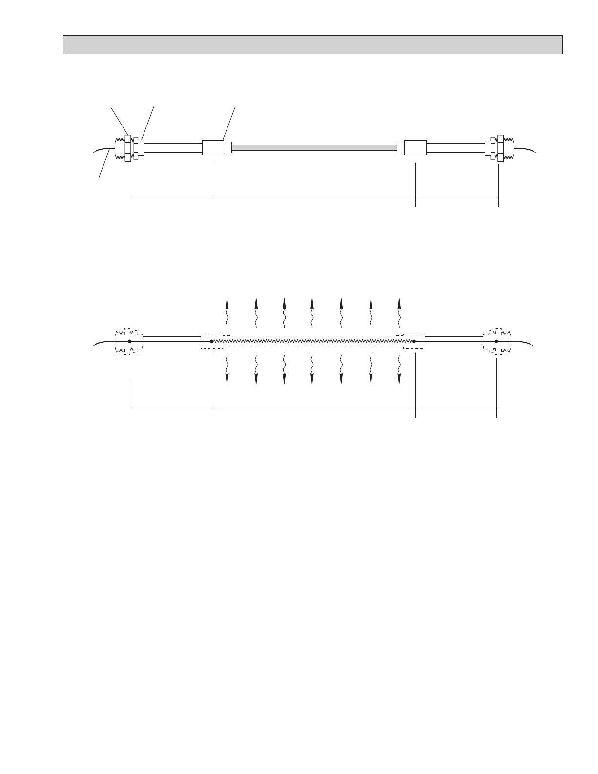
Internal View
HEATER CONSTRUCTION AND OPERATION
Phone: (800) 324-1551 Fax: (918) 251-6079 www.trasor.com Page 5
Supply
Voltage
Figure 2
Heater Output (w/ft)
Hot to Cold
Joint
Termination
Gland Fitting
Pigtail
General Heater Construction
Figure 1
Hot Section Cold Lead
V (L1) V (L2)
Cold Lead
Resistive Conductor
Copper
Conductors
Copper
Conductors
V Voltage = I * R
I Current = V ÷ R
W Wattage = V * I = I ² * R = V² ÷ R
w/ft Watts per foot = W ÷ L = I² * Ω/ft
R Resistance = L * Ω/ft = V ÷ I
L Heater length = R ÷ Ω/ft
Ω/ft Published cable resistance ≈ R ÷ L
Variables and Formulas:
Note, Form “B” one conductor heater is shown in the
above figures. Form “B” is the most common form used
in snow melting applications. It offers a comprehensive
selection of resistances. There is also a one
conductor form “C” and a two conductor form “A”.
See page 6.
General Operation:
MI heating cable is a series resistance heater that has
a constant output along the entire length of the heater.
It’s operation is consistent with Ohm’s Law.
Cold Lead
Termination
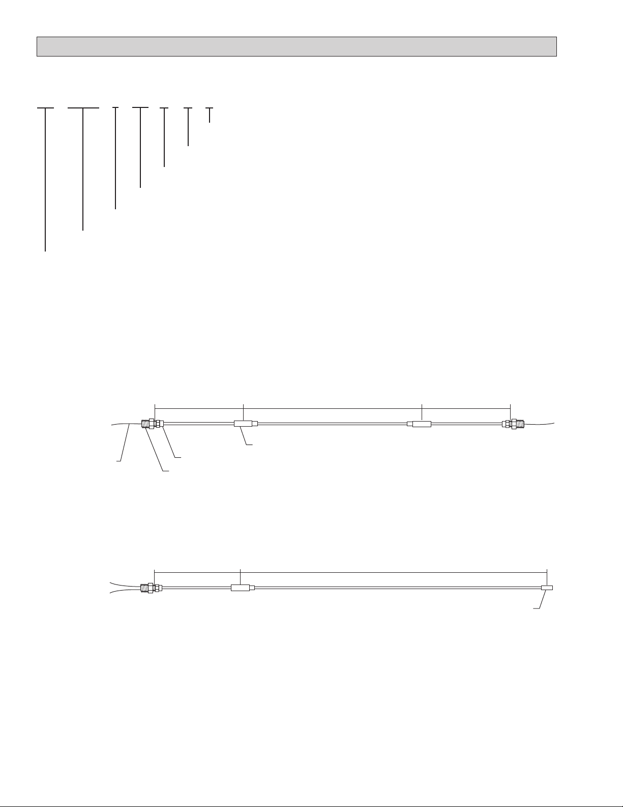
HEATER PART NUMBER SYSTEM & HEATER FORMS
Phone: (800) 324-1551 Fax: (918) 251-6079 www.trasor.com Page 6
Heater Part Number System:
Cold Lead
Form A/AN
Two Conductor
Cold Lead
Hot Section
Hot Section Cold Lead
Heater Forms:
Form B/BN
One Conductor
End Cap
Termination Gland Fitting
Hot to Cold Joint
Pigtails
Figure 4
Figure 3
Cold Lead Termination
MIE - R21EH - B - 200 - 07 - 07 - X
Special feature, see datasheets for details
Cold section length (FT.)
Hot section length (FT.)
Heater unit form, see figures 3 & 4 for details
Heater unit hot section size, see datasheets for details
Heating cable type, see datasheets for details
Cold section #2 length (FT.), if applicable
Phone: (800) 324-1551 Fax: (918) 251-6079 www.trasor.com Page 7
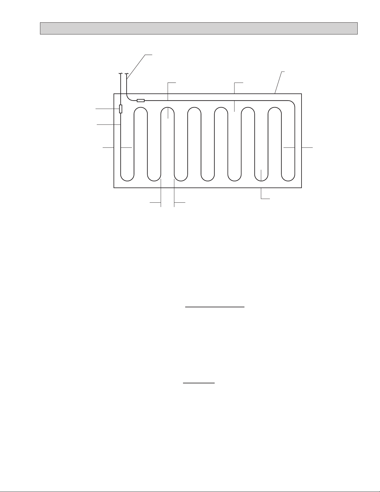
GENERAL HEATER LAYOUT & CABLE SPACING
(S/2)(S/2)
(S/2)
(S/2)
(S), Cable Spacing
General Cable Layout
Layout heating cable as shown in Figure 5 or layout
drawings. When installation and layout drawings are
provided, verify heated areas match what are shown on
the drawings and confirm all dimensions. Follow pattern
and cable spacing (S) on drawings. If drawings are not
provided calculate cable spacing using equation 1.
2
Heated Area (ft) 12 (in/ft)
Heater Length (ft) X
Example:
2
Heated Area = 120 ft
Heater Length = 180 ft
2
120 ft 12 (in/ft) = 8” spacing
Spacing (S) =
180 ft X
Figure 5
Spacing (S) =
Equation 1
Slab
Hot to Cold joint
Heating cable
Cold lead, see details pages 10 thru 13
(S/2)

Phone: (800) 324-1551 Fax: (918) 251-6079 www.trasor.com Page 8
INSTALLATION GUIDELINES
Project Coordination Meeting:
Before the project begins, a project coordination meeting
should be held with all trades that will be involved with the
installation of the heating cable, pouring of the slab and
cutting or drilling into the slab. Coordination of these
trades is extremely important. It can be catastrophic for a
heater to be cut through with a saw or drilled into for a rail
post. The following topics should be covered:
1. Review of all layout drawings and instructions.
2. Review slab construction and support media for
cable. Confirm cable depth and cable spacing.
3. Confirm all expansion and construction joint locations
and mark in the field on the slab forms so they are
apparent to all crafts.
4. Confirm all locations of rail supports, doorstops, signs
or drains.
5. Confirm heating termination method to be used. See
pages 10 thru 13.
6. Confirm junction box and control locations.
7. Confirm locations and make provisions for slab
sensors or warning markers.
8. Coordinate testing and record keeping between
installation procedures. See pages 21 and 22.
General Installation Notes:
1. Follow all installation and layout drawings. Verify
heated areas match what are shown on layout
drawings and confirm that all dimensions on drawings
match field dimensions.
2. Unpack and test all heaters to verify there was no
damage from shipping. Reference testing
procedures on page 21 and record values in table 1
on page 22. Make copies of table 1 for each heater.
Test heaters again before installation, after they are
secured to the reinforcement media, while the heaters
are being embedded in slab and after slab is
complete.
3. The heater, cold lead termination and pigtails must be
kept dry, protected from weather and mechanical
abuse before, during and after installation.
4. Protect heating cable from being walked on, driven
on, sharp materials, weld slag or being cut.
5. Verify proper heater is selected for area shown on
drawing. Heaters cannot be randomly switched. All
heaters are provided with a stainless nameplate. The
nameplate will have tagging information and
electrical ratings.
6. Confirm proper slab reinforcement is in place and at
proper depth. Heating cable must be secured at a
minimum depth of two inches from slab surface. It is
not recommended to exceed a depth more than three
inches. This will extend the heat up time and reduce
heat getting to the surface.
7. Prepare area for heating cable. Follow layout
drawings for proper cable spacing and routing path.
Mark cable paths with chalk or spray paint. Do not
locate heating cable within six inches any future slab
penetrations, such as handrails, drill holes or drains.
8. If layout drawings are not provided calculate cable
spacing using equation 1 on page 7.
9. Uncoil or roll out the heater. Do not pull cable from
center of coil into a spiral.
10. Minimum bending radius of heating cable is 6 x the
cable diameter.
11. Do not bend the cable within 3” on any hot to cold joint,
termination or splice joint. Almost all heaters that are
broken during installation occur at the hot to cold joint
due to mishandling.
12. Do not repeatedly bend and straighten the cable.
13. Do not install cable so that it may touch or be within 3”
of another cable pass.
14. Do not pass heating cable through expansion, control
or construction joints unless using methods shown in
detail 9, 10 or 11 on pages & 10 on page 18.
15. If any cable is damaged or broken, stop installation
and seal break with silicone and contact the factory.
16. Start heater installation with the first cold lead.
Secure with nylon ties three inches from each side of
the hot to cold joint.
17. Handle hot to cold joint carefully. Support both sides
when moving and positioning cold lead.
18. Secure heating cable to rebar or reinforcement mesh
every 12 to 18 inches with nylon ties. Do not use steel
ties.
19. When approaching the end of a heater installation,
adjust the last few passes as need so the end of the
heater is at the point specified in the layout drawing.
20. Note any variations of cable routing or termination
locations on project drawings and return to owner and
factory. This is valuable information if repairs or
trouble shooting is required in the future.
21. Terminate heaters to junction box as shown on pages
10 or 12.
22. IMPORTANT: The termination gland fitting is the
grounding mechanism for the heater. This must be
connect by an NEC approved grounding method.
23. Junction boxes and enclosures for electrical
connections to the heating cable must be listed and
approved for the environment in which they are
installed.

Phone: (800) 324-1551 Fax: (918) 251-6079 www.trasor.com Page 9
INSTALLATION GUIDELINES
Slab & Paving Construction Guidelines:
Proper slab design is essential to a successful system.
The size, thickness, reinforcing media, and general
design must be such that the slab will not crack, causing
damage to the heating cable.
The slab base should be smooth and adequately
compacted to prevent settlement, and care should be
taken to make certain that tree roots will not cause future
heaving.
Proper design should include provisions for water runoff.
This water could cause the slab to heave if it accumulated
in the base, or it could cause a dangerous ice condition at
the foot of a sloping drive. If adequate natural drainage is
not available it may be necessary to install a drain. In
some instances the drain may have to be heated to
prevent freezing.
Installing Cable in Concrete:
Rebar is the preferred reinforcement material for
embedded heating cable in concrete. It provides
maximum strength and is more apt to keep heating cable
at a consistent depth. The spacing of the rebar is often
wider than reinforcement mesh. This makes it easer for
the installer to step into the area while securing the cable.
See detail 1 on page 14.
It is recommended that a ground-supported slab be no
larger than 20 feet by 20 feet, with a minimum thickness of
4 inches for walkways or 6 inches for areas supporting
motor vehicles.
Cable depth should be 2 to 3 inches below the finished
surface of the slab. The cable should be secured to rebar
or reinforcement mesh with nylon ties. Do not use steel tie
wire. Secure cable every 12 to 18 inches.
When installing cable on an existing slab or using a two
pour method, secure the cable to the first slab using
spacer strip. See detail 2 on page 14.
If heater is damaged while concrete is being pored, box
off 24” square area around damaged cable and clear out
concrete. Seal break with silicon and contact the factory.
Installing Cable in Asphalt:
The base or foundation course must be designed so that
the heater unit will not be damaged due to movement.
The heated area of an asphalt slab must be held well in
from the edges unless there is adequate provision made
to prevent the possible collapse of the edges.
The top course of asphalt should have a minimum
thickness of 2 inches after compaction.
The heater should be installed into a uniform pattern as
specified and held in position on the base slab using
spacer strip. For added security, reinforcement mesh
should secured over the cable and spacer strip. See
detail 3 on page 15.
After the cables are in position, place a layer of asphalt
about 1” thick over the cable by hand. Roll this with a
small roller. This will protect the cable from tools or
paving equipment during placement of top course.
Do not dump piles of asphalt in small area of cable and
spread out. This may damage jacketed heating cable
from the concentrated heat of the asphalt.
Installing Cable under Pavers and Bricks:
Secure the cable to masonry reinforcing over a concrete
base or 1 inch of well compacted sand or lime stone
screenings. Cover the heating cable with 1” of
compacted sand or lime stone screenings. See detail 4
on page 15. Use caution when setting pavers not to
damage heating cable.
Note: Cable spacing is typically tighter under pavers (4 to
6 inches) due to the poor conductivity of brick and pavers.
Heater Cold Lead and Pigtail Lengths:
Each heater has cold leads and pigtails. The lengths of
these components can vary per system design and
requirements.
Heaters with standard 11” pigtails are used when the
junction box locations are local and close to the slab. The
locations are specified and will not vary in the field.
Typically these heaters will have 7' to 15' cold leads to
reach the junction box. See pages 10 and 11.
Heaters with extended pigtails are used when the
junction box locations are remote. The locations are field
located and may be 20 to 50 feet from slab. Typically
these heaters will have 2' cold leads with long pigtails to
reach the junction box. See pages 12 and 13.
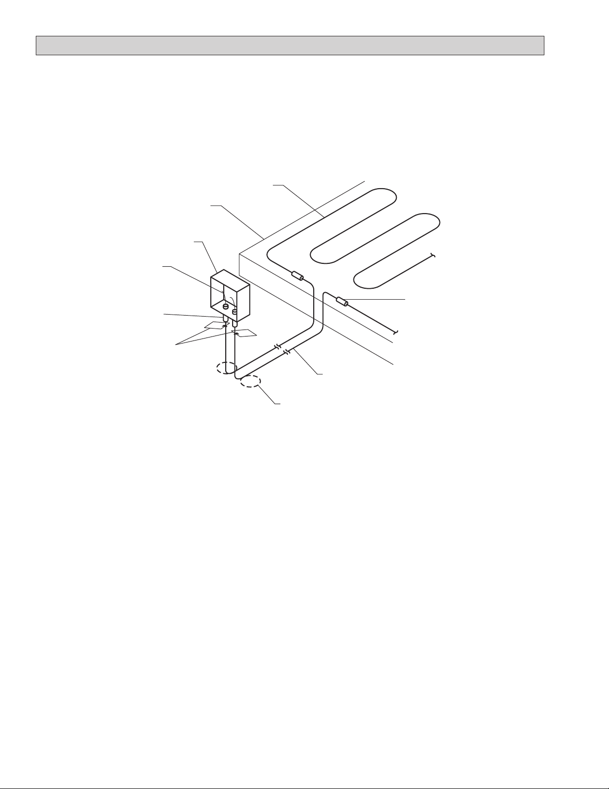
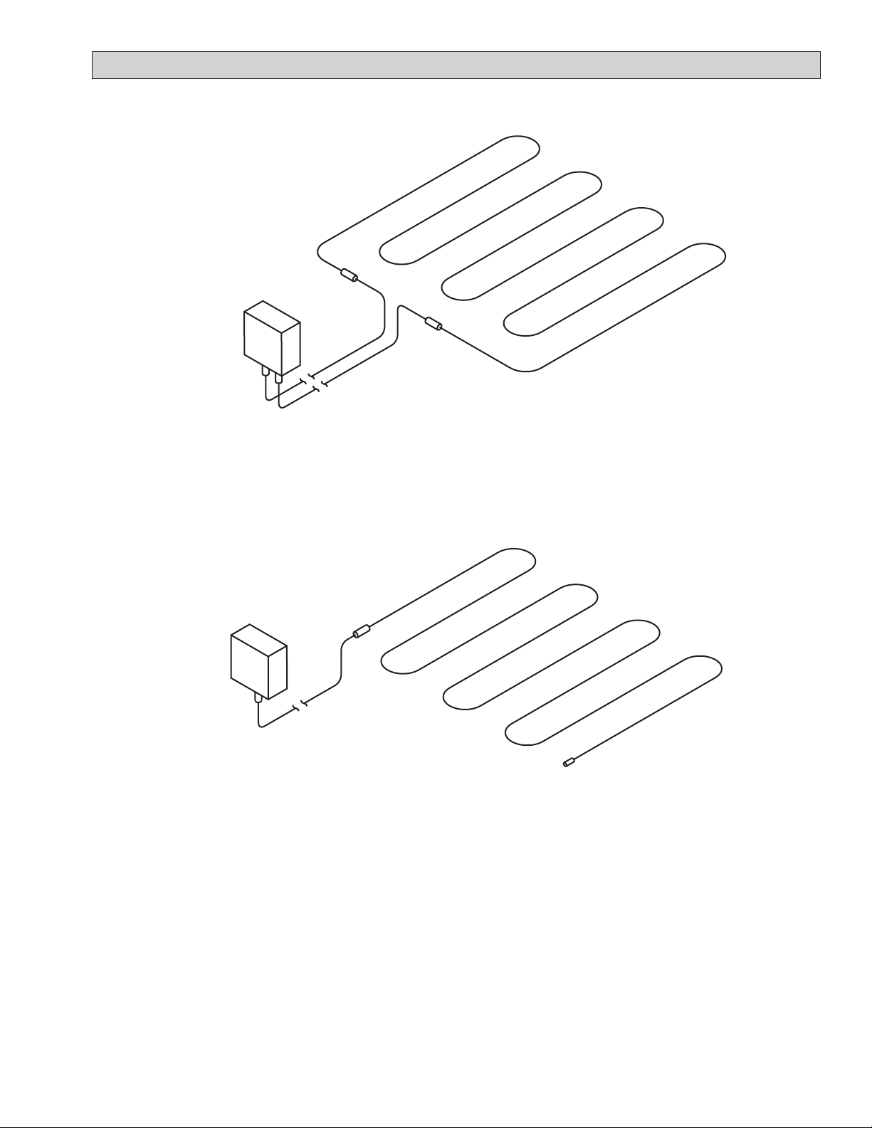
INSTALLATION STEPS FOR HEATERS WITH STANDARD PIGTAILS
The cold leads for heaters with standard 11” pigtails will
extend out of the slab and terminate directly into a local
junction box. The cold leads are typically 7 to 15 feet or
longer. This method is used when the junction box
locations are specified and will not vary in the field. Note,
cold lead lengths cannot be modified in the field.
Figure 6
Coil extra cold lead into 4” to 6”
coils and bury under junction box.
Above grade junction box
Heating cable
Cold lead
Hot to cold joint
Stainless name tags
Slab
Phone: (800) 324-1551 Fax: (918) 251-6079 www.trasor.com Page 10
Pigtails
Installation Steps for Heaters with Standard 11” Pigtails:
1. Secure the hot to cold joint of the first cold lead to the
reinforcement media. Place ties 3 inches from each
side of the hot to cold joint.
2. When possible pass the cold lead out through the
bottom of the slab.
3. Install heating cable as described in the previous
sections.
4. Secure the second cold lead to the reinforcement
media as describe in step one. Note, heater forms
“A” and “C” will not have a second cold lead.
5. Route the cold leads back to the junction box. Bury
any extra cold lead in small 4”+ coil underneath the
junction box. Note, cold lead lengths cannot be
modified in the field.
6. Secure termination gland fitting to junction box or
controller.
7. Pass pigtails through termination gland fitting.
8. Push cold lead termination midway into termination
gland fitting. Tighten ferrule side of the gland fitting.
Use care not to twist termination or cold lead cable.
9. Test insulation resistance (Megger) and heater
continuity and record values. See pages 21 and 22.
10. Note: Termination gland fitting provides ground
connection for heater. NEC approved grounding
method must be used at junction box.
11. Junction boxes and enclosures for electrical
connections to the heating cable must be listed and
approved for the environment in which they are
installed.
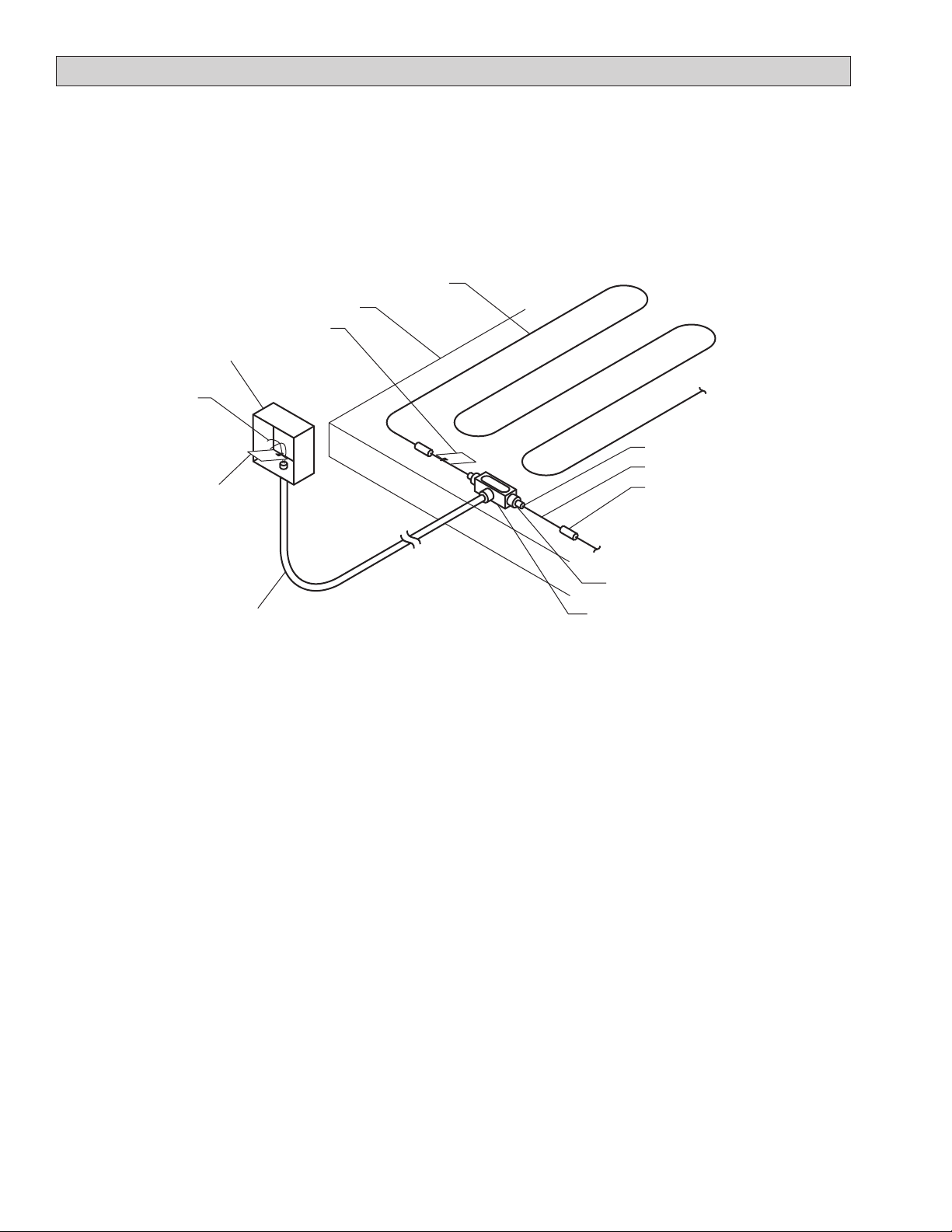
Terminating Heaters with Standard Pigtails:
Termination gland fitting
Note, Form “B” heater shown. Forms “A”
and “C” are shown on the following page.
Phone: (800) 324-1551 Fax: (918) 251-6079 www.trasor.com Page 11
INSTALLATION STEPS FOR HEATERS WITH STANDARD PIGTAILS
Figure 7
Figure 8
Form “B” Heater:
Termination of form “B” heater with standard pigtails.
Form “A” Heater:
Termination of form “A” heater with standard pigtails.
Phone: (800) 324-1551 Fax: (918) 251-6079 www.trasor.com Page 12
INSTALLATION STEPS FOR HEATERS WITH EXTENDED PIGTAILS
1. Uncap conduit body and verify it is dry and free of
moisture.
2. Install conduit body so that opening is facing up.
3. Secure termination gland fitting into conduit body.
4. Carefully pass the pigtails from the first cold lead
through the termination gland fitting.
5. Push cold lead termination midway into the
termination gland fitting. Tighten ferrule side of the
gland fitting and use care not to twist termination or
cold lead cable.
6. Install and secure heating cable as described in
previous sections.
7. Using the pigtails from the second cold lead, follow
step 3,4 & 5. Note, heater forms “A” and “C” do not
have a second cold lead.
8. Pull pigtails and ground wire, if required, through
conduit to the junction box or controller. Ground
wire must be provided when using plastic piping.
See detail 13, page 20.
9. Remove one of the stainless nameplates from a cold
lead and secure it to a one of the pigtails at the
junction box. This tags has important electrical
ratings and part number information.
10. NEC approved grounding method must be used at
junction box.
11. Test insulation resistance (Megger) and heater
continuity and record values. See pages 21 and 22.
12. Apply duct seal between conduit body and conduit.
IMPORTANT, Fill conduit body with 3M Scotch Cast
8882. See details 12 and 13, page 20.
13. Junction boxes and enclosures for electrical
connections to the heating cable must be listed and
approved for the environment in which they are
installed.
Figure 9
Hot to cold joint
Above grade junction box
Heating cable
Cold lead
Field routed conduit
3/4” metallic conduit, See detail 12, page 20.
3/4” PVC with ground wire. See detail 13, page 20.
Metallic conduit body
See details 12 & 13, page 20
Pigtails
Termination gland fitting
Stainless name tag
Slab
Stainless name tag
Cold lead termination
Installation Steps for Heaters with Extended Pigtails:
Terminating eaters with igtailsH Extended P :
Note, Form “B” heater shown. Forms “A”
and “C” are shown on the following page.
The cold leads for heaters with extend pigtails will
terminate into a conduit body located within the slab. The
pigtails will be pulled through field routed conduit and
terminate into a remote junction box. The cold leads will
typically be 2' long and have stranded pigtails that may be
20 to 50 feet in length. This method is used when there is
a long distance between the heater and the junction box.
Heaters with pigtails longer than 1 foot are noted as
having extended pigtails. The part numbers for thess
heaters will have a special feature suffix “T**”. The ** will
indicate the pigtail length in feet.

Phone: (800) 324-1551 Fax: (918) 251-6079 www.trasor.com Page 13
INSTALLATION STEPS FOR HEATERS WITH EXTENDED PIGTAILS
Figure 11
Form “B” Heater:
Termination of form “B” heater with extended pigtails.
Form “A” Heater:
Termination of form “A” heater with extended pigtails.
Figure 10
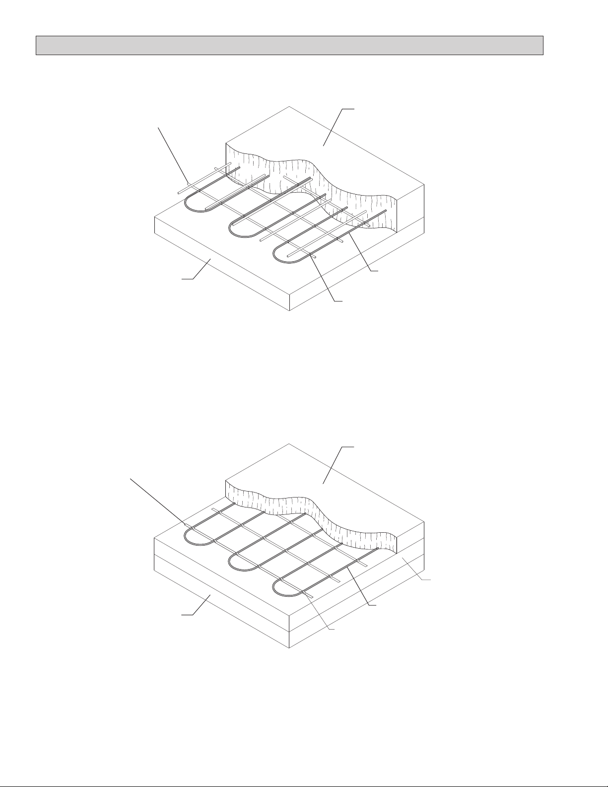
SLAB INSTALLATION DETAILS
Phone: (800) 324-1551 Fax: (918) 251-6079 www.trasor.com Page 14
Heating cable
Secure cable to rebar or mesh with nylon ties
ever 18 to 24 inches and at turns and loops.
Concrete, 2” minimum cover over
heating cable.
Rebar or reinforcing mesh.
Installing in Concrete, Single Pour Slab
(Heating cable secured to rebar or wire mesh)
Structurally sound,
well drained base.
Concrete base
Secure cable under tabs of spacer strip.
See detail 8, page 17.
Spacer strip nailed to base pour.
Heating cable
Structurally sound,
well drained base.
2” to 3” Concrete cap over heating cable.
Installing in Concrete, Two Pour Slab
(Heating cable secured with spacer strip)
Detail 1
Detail 2

SLAB INSTALLATION DETAILS
Phone: (800) 324-1551 Fax: (918) 251-6079 www.trasor.com Page 15
Secure spacer strip to asphalt
base with concrete nails.
Structurally sound well,
drained base.
Installing in Asphalt
(Heating cable secured with spacer strip & covered with wire mesh)
2” Minimum asphalt base.
Secure cable under tabs of spacer strip.
See detail 8, page 17.
Heating cable
2” to 3” Asphalt cap.
Cover heating cable with wire
mesh and anchor to base.
Masonry reinforcement on 36” centers.
Structurally sound well,
drained base.
Installing under Pavers
(Heating cable secured with masonry reinforcement)
1” Sand or limestone
screenings.
Secure cable with nylon ties.
Heating cable
2” to 3” Pavers
1” Limestone screenings or
sand over heating cable.
Detail 3
Detail 4
Phone: (800) 324-1551 Fax: (918) 251-6079 www.trasor.com Page 16
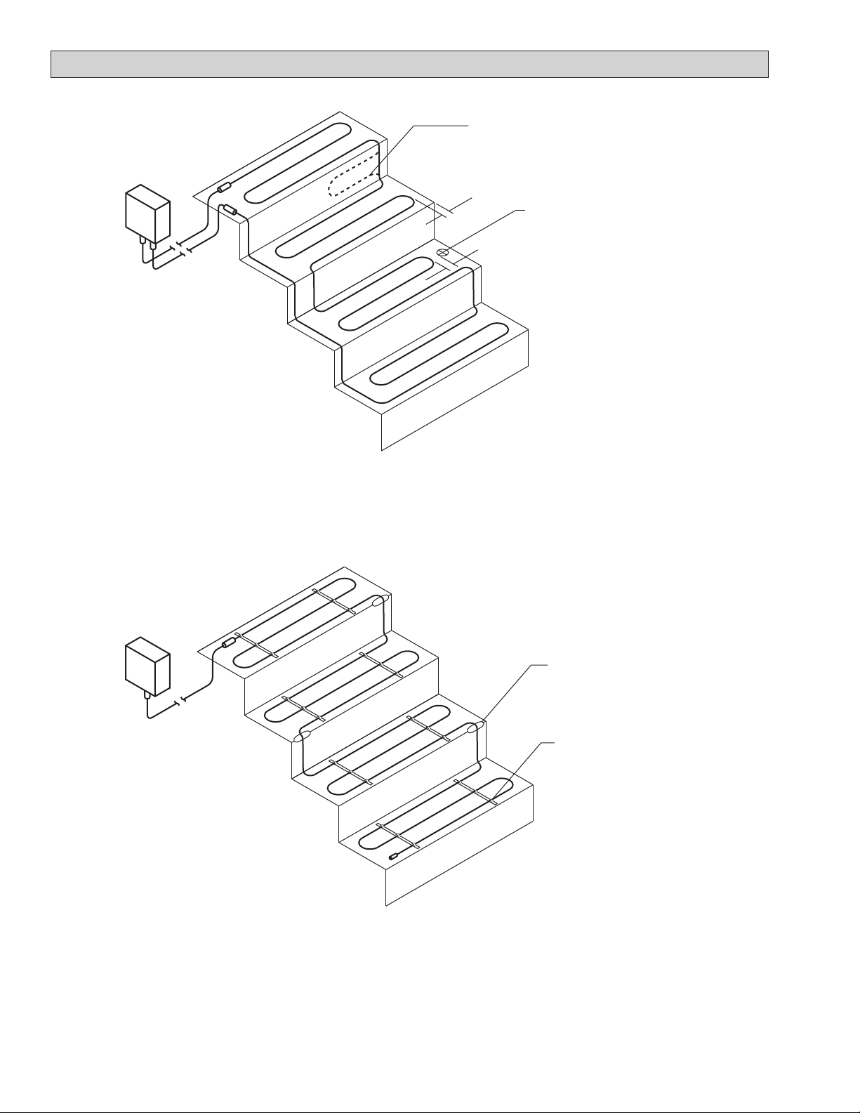
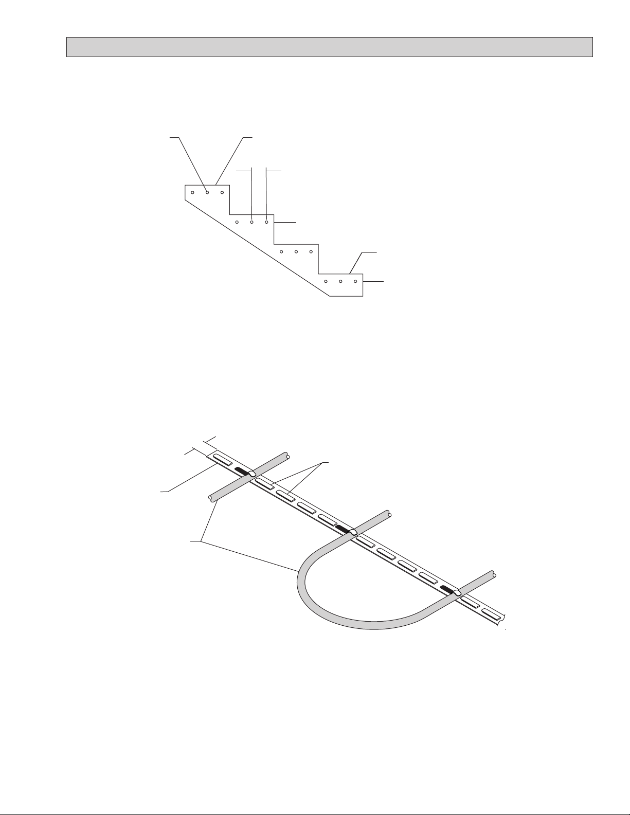
INSTALLATION IN STAIRS
Installing in Stairs, Single Pour Method
(Heating cable secured with rebar. See detail 1, page 14.)
Form “B” heater shown
Installing in Stairs, Two Pour Slab
(Heating cable secured with spacer strip. See detail 2, page 14 & detail 8, page 17.)
Form “A” heater shown
Detail 5
Detail 6
Mark locations where hand rail posts
will be installed. Keep heating cable
at least 6” away from these areas to
avoid damaging the cable when rail
posts are installed.
6”
4”
Round corners off to prevent
cable damage.
Secure heating cable to first slab
with spacer strip. See Detail 2
page 14 & Detail 8 page 17.
Use up any extra cable on risers,
landings or add an extra pass.
Maintain at least 3” spacing.
Phone: (800) 324-1551 Fax: (918) 251-6079 www.trasor.com Page 17
STAIR INSTALLATION DETAIL
2” Cover over heating cable.
4” Typical spacing, 6” Max
Keep edge pass 2” from Riser and Tread.
Tread
Riser
Heating cable
Side View, Heating Cable in Stairs
(Secure cable to rebar with single pour method. See detail 1, page 14.)
Secure cable with spacer strip with two pour method. See detail 2, page 14.
Detail 7
Spacer Strip Detail
(Securing heating cable with spacer strip)
Detail 8
Spacer strip
Tabs at 1” spacing
Nail spacer strip to sub surface.
Bend tabs over heating cable to
hold cable at uniform spacing.
Heating cable
½”

INSTALLATION DETAILS
Phone: (800) 324-1551 Fax: (918) 251-6079 www.trasor.com Page 18
Crossing Control or Construction Joint
(Single pour slab)
Control or construction joint
Detail 10
Crossing Control or Construction Joint
(Two pour or single pour slab)
1” x 1” x 12” Angle iron filled with silicon
Control joint
Heating cable
Detail 9
Control joints are intended to control where that slab will
crack. It is important that the locations of these joints are
specified before the cable is installed or slab is poured.
Because of the reinforcement in the slab, there is rarely a
shearing action caused by differential vertical movement
between the concrete on either side of the crack. As a
precautionary measure, use either of the two methods of
crossing as shown in detail 9 or 10. When possible
minimize the number of times the joint is crossed as
shown in detail 9. When installing cables using the two
pour method, control joint must be placed in the base slab
and the surface slab.
Construction joints are joints that occur when the
concrete pour is going to stop but will resume at a later
date. The reinforcement should be left protruding out of
the first pour so that it enters the next pour and therefore
shearing action rarely occurs. Use either of the two
methods of crossing as shown in detail 9 or 10.
Crossing Control or Construction Joints:
Rebar
Heating Cable
Secure heating cable to rebar with nylon ties.
Slab
Structurally sound,
well drained base.
Phone: (800) 324-1551 Fax: (918) 251-6079 www.trasor.com Page 19
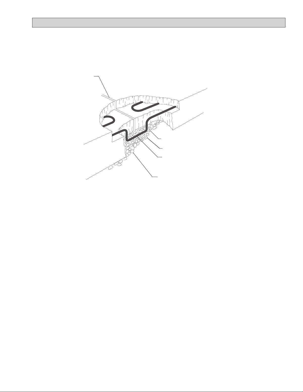
INSTALLATION DETAILS
Expansion Joint Detail
(Heating cable passed under joint)
Gravel base
Sand
Heating Cable
Expansion Joint
Detail 11
Expansion joints are placed where a concrete slab abuts
some structure, such as a building, slab, or a foundation.
Because the reinforcement does not cross expansion
joints, differential movement will occur between the slab
and the adjoining structure. Avoid crossing expansion
joints with the heating cable. If this is not possible,
expansion joints can be crossed using method shown in
detail 11.
Cable Crossing Expansion Joints:
Solid pocket of base to hold sand.

INSTALLATION DETAILS
Phone: (800) 324-1551 Fax: (918) 251-6079 www.trasor.com Page 20
Conduit Body Detail - Metallic Conduit
(Heater termination with long pigtails. See pages 12 & 13.)
Conduit Body Detail - Plastic Conduit
(Heater termination with long pigtails. See pages 12 & 13.)
Fill conduit body with 3M Scotch
Cast 8882.
Metallic 3/4” NPT conduit body.
Termination gland fitting
Cold lead termination
Metallic conduit
Long pigtails
Seal around pigtails
with duct seal putty.
Fill conduit body with 3M Scotch
Cast 8882.
Metallic 3/4” NPT conduit body with
internal ground screw.
Termination gland fitting
Cold lead termination
Detail 13
Detail 12
Long pigtails
Ground wire
Plastic conduit
Seal around pigtails
with duct seal putty.
Ground wire attached to
internal ground screw.
IMPORTANT:
Metallic conduit body provides
ground path for heater sheath.
All heaters must be grounded
by an NEC approved method.
IMPORTANT:
Metallic conduit body and metallic
conduit provides ground path for
heater sheath. All heaters must be
grounded by an NEC approved
method.
Cold lead
Cold lead
Table of contents
Popular Snow Blower manuals by other brands


Craftsman
Craftsman 247.886510 owner's guide

Husqvarna
Husqvarna 924SBE Illustrated parts list

Briggs & Stratton
Briggs & Stratton 1695979 Safety, operation & maintenance manual

Poulan Pro
Poulan Pro 437139 owner's manual

Grizzly
Grizzly ESF 2046 L Translation of the original instructions for use

Toro
Toro 1800 Power Curve Set-up/Assembly


