Travel Vision Dish Diversity Switch Instruction Manual
www.travel-vision.com
Dish Diversity Switch
INSTALLATION & USER’S MANUAL
Version 3.1 October 2013

Page 2
PREFACE
The information in this Installation and User’s Manual is subject to change in order to
improve reliability, design or function without prior notice.
In no event Travel Vision B.V. will be liable for technical or editorial errors or omissions
herein. Nor for incidental, special or consequential damages from the furnishing,
performance or use of this Installation and User’s Manual.
WARNINGS AND NOTICES
Follow instructions and heed all warnings in this Installation and User’s Guide.
To reduce the risk of electric shock, do not remove the cover of the Dish Diversity Switch.
No user serviceable parts inside, refer servicing to qualified personnel.

Page 3
Content
1. System description page 4.
2. Hardware installation page 5.
2.1 General Installation page 5.
2.2 Coax cable routing page 5.
2.3 Wiring schematic page 6.
3. Software configuration page 6.
3.1 Level detection page 7.
3.2 Calibration page 7.
3.3 Default settings page 8.
3.4 Menu page 9.
4. Specifications page 10.

Page 4
1. System Description
Travel Vision’s Dish Diversity Switch was developed to fit the needs of ship owners to
have an antenna switch that does not depend on the brand and type of satellite antennas.
The Travel Vision Dish Diversity Switch doesn’t need to communicate with the antenna
controller units. The Dish Diversity Switch takes RF-signal samples from both antennas
and determines entirely autonomous which satellite antenna has the strongest signal. The
signal from that antenna is then routed to a connected head-end or receivers. The Dish
Diversity Switch also has a mechanism to compensate for different cable lengths.

Page 5
2. Hardware Installation
2.1 General Installation
The Dish Diversity Switch is provided with an Euro style Power cord and plug.
Before start doing any work, please make sure main power is disconnected.
The system is designed to be installed in a 19inch cabinet rack. The Dish Diversity Switch
has a standard height of 1U.
2.2 Coax cable routing
Interfacing the Dish Diversity Switch
The red loops in the drawing above are coaxial loops that connect the output of the signal
level detector to an input of the switch.
By default the loops are placed onto the Horizontal low band input. This means that the
coax cable from Dish1 LNB low Horizontal band shall be connected to input Detector
Dish1 In. The Coax cable from Dish2 LNB Low Horizontal band should be connected
to input Detector Dish 2 in.
Any band can be used for signal strength measurement as long both detector inputs are
connected to the same signal band. It’s preferred to use a signal band that has multiple
steady carriers. Although the switch section was designed to give minimum attenuation
and maximum flatness over the entire L-band, it does introduce a signal loss of
approximately 3dB.
The signal band that is routed through the Detector experiences an additional attenuation
of approximately 1dB. This additional attenuation is mainly introduced by the F-connectors
and the coaxial wiring internally and the loops externally.
If the systems signal level overhead is smaller than 4 dB, low gain amplifiers must be used
to compensate the additional losses introduced by the Dish Diversity Switch.

Page 6
2.3 Wiring Schematic

Page 7
3. Software configuration
The Dish Diversity Switch operates under embedded software control.
If power is applied to the unit, the software will start automatically and no user intervention
is needed. The embedded software can be updated using an USB memory stick.
3.1 Level detection
When main power and RF cables are connected, the software starts and will display the
measured signal levels from Dish 1 and Dish 2.
If the detector has no signal or a level that is too low, display will show <-65 dBm.
If the level is too high display will show >-25 dBm.
The level displayed is in dBm units, this level displayed cannot be compared to the levels
that one would read from a spectrum analyzer. The used level detection measures the RF
power across the entire L-band instead of a single transponder.
3.2 Calibration
Calibration must be done after complete installation of all RF cables.
The purpose of calibration is to compensate for different cable lengths and signal levels.
Make sure that both satellite dishes are tracking the same satellite and have a clear view.
Calibration can be done best if the vessel anchored or on a steady course at calm seas.
For calibration enter the installation menu by pressing the <Enter> (
) and <Esc> (
)
keys for 4 seconds. Then scroll down the menu pressing the ↓key until Calibrate is
displayed. Then press <Enter> to start the calibration routine. At this point the control unit
reads multiple RF-signal samples from both dishes, samples are compared against each
other and stored into non volatile memory. If calibration is done leave the menu by
pressing <Esc>.

Page 8
3.3 Default Settings
The following settings are default. They can be changed by the user. Changing these
setting will affect the systems performance. We advise not to change any settings unless
you are a certified mechanic.
Setting Default
Auto/Manual Auto
Switch Delay 1 second
RF Power Threshold 02 dB
Backlight On
Backlight Intensity maximum
Page 9
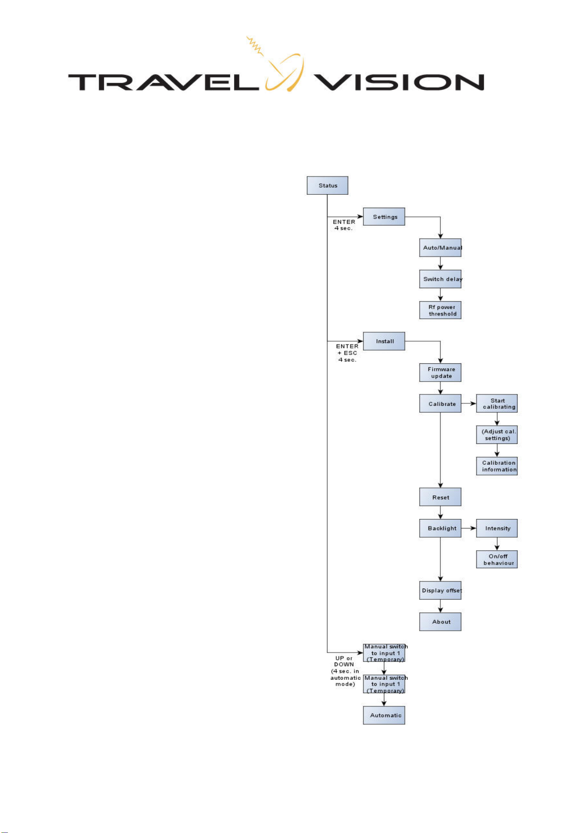
3.4 Menu
When a key, or combination of keys is
pressed an user can enter different menu
functions.
To enter the settings menu, press Enter
for 4 seconds.
To enter installation menu, press Enter
and Escape
together for 4 seconds.
When the switch is in automatic mode you
can manually select an input by pressing
the UP or Down key for 4 seconds.
Please note that this menu is not available
when the switch is in manual mode.

Page 10
4. Specifications
Power Supply Universal 100..240 Volt AC, 50..60 Hz 25 Watt maximum
Power cord plug type Euro
Dimensions 19 inch rack mount, 1U height.
RF detector
Frequency range L-band (950..2150 MHz)
Impedance 75 Ohm
Connectors F-connector female (high performance type)
Pass through loss <1dB typical
RF level handling -65dBm to -25dBm
Switch Section
Frequency range L-band (950..2150 MHz)
Impedance 75 Ohm
Connectors F-connector female (high performance type)
Pass through loss <3dB typical
RF level handling -65dBm to 30dBm (1Watt absolute maximum)
Isolation between Ports > 30 dB typical
Isolation Port to Port > 35 dB typical
DC current path All port have a DC pass (jumper selection pass no-pass)
Maximum DC current 800 mA
Table of contents
Other Travel Vision Switch manuals


