Trejon OPTIMAL VP Series Specification sheet

Instructions for Use and
Maintenance
V-plough
VP150-VP320
Note! Read instructions before use.
TREJON AB
Företagsvägen 9
SE-911 35 VÄNNÄSBY
SWEDEN
Tel: + 46 (0)935 39 900
Fax: + 46 (0)935 39 919
From year 2007-08

Instruction manual OPTIMAL VP150-VP320 (0911)
trejonindustries.se
2
SAFETY SYMBOLS
Note! This warning symbol is used throughout this instruction manual to call attention to safety
precautions that you, your employees or any other people that may come near the implement must
read and understand. Failure to follow these instructions may result in serious injury or even death.
This symbol means:
WARNING!
CAUTION!
YOUR SAFETY IS
ENDANGERED!
A word of advice
Pay special attention to the words WARNING!, CAUTION! and NOTE! in the safety instructions.
The words have been chosen from of the following:
WARNING! This safety sign is used to identify potential hazards that can lead to serious injury or
even death. These hazards include situations that may occur when the safety equipment and/or
the safety shields are removed. Signal words can also be used to alert about dangerous use.
CAUTION! Failure to observe this warning sign could result in light personal injuries. The sign is
also used to indicate that the disregarding of these instructions may cause damage to the
implement.

Instruction manual OPTIMAL VP150-VP320 (0911)
trejonindustries.se
3
Dear Customer,
You have made a good choice. We congratulate you to your selection of an OPTIMAL product that
offers quality and performance with reliable service.
By reading the manual and following its recommendations you will ensure the long and effective
use of the equipment.
We have produced this manual for you to get a good understanding of the functioning of the
equipment and what safety and maintenance instructions to follow when working with it.
If any question should arise when using the equipment or when reading this manual, you are
welcome to contact us for further information.
TREJON AB
Företagsvägen 9
SE-911 35 Vännäsby
Sweden
Tfn: + 46 (0)935 39 900
Fax: + 46 (0)935 39 919,
Repair parts: +46 (0)935 20241
Email: [email protected]
Website: www.trejonindustries.se

Instruction manual OPTIMAL VP150-VP320 (0911)
trejonindustries.se
4
Honoured retailer,
in order for the guarantee to be valid and to forfill all legal requirements, we ask you to fill out the
guarantee form together with the customer and return it to TREJON.
The guarantee is valid from the day the equipment is handed over to the customer.
Delivery checklist:
Check for damages caused in transporting. Inform the transporting company.
Check that all packing material has been taken away. Dispose packing material in an
environmentally friendly way
Check that the machine is lubricated, see section “Service and maintenance”.
Check that all screws are properly tightened, see section “Service and maintenance”.
Make a function test.
Having gone through and explained to the customer, with the help of the manual, the
startup, use and maintenance of the equipment and it’s accessories.
Fill out the guarantee form with the customer and send it to TREJON AB. It can be
found as an attachment to this manual and as a copy on the last page.
Instruction manual given to the customer.
Enter the serialnumber of the equipment to the
right. S/N:

Instruction manual OPTIMAL VP150-VP320 (0911)
trejonindustries.se
5
TABLE OF CONTENT
1Introduction..............................................................................................................................6
1.1 Description of V-plough.......................................................................................................6
2Safety instructions...................................................................................................................6
3Technical description..............................................................................................................7
3.1 Attachment..........................................................................................................................7
3.2 Skid shoes ..........................................................................................................................7
3.3 Scraper steels.....................................................................................................................7
3.4 Hydraulics...........................................................................................................................7
4Technical data..........................................................................................................................8
5Installation................................................................................................................................9
5.1 Lifting instructions...............................................................................................................9
5.2 Attaching the plough to the vehicle...................................................................................10
5.3 Hydraulics.........................................................................................................................10
5.4 Electricity...........................................................................................................................10
5.5 Hand unit...........................................................................................................................11
6Assemble................................................................................................................................12
7Driving instructions...............................................................................................................13
8Service and maintenance......................................................................................................14
8.1 General maintenance........................................................................................................14
8.2 Lubrication ........................................................................................................................14
8.3 Scraper steels...................................................................................................................14
8.4 Long term storage.............................................................................................................14
9Spare parts .............................................................................................................................15
9.1 Use original spare parts....................................................................................................15
10 Notes.......................................................................................................................................16
EC-Certificate of Conformity........................................................................................................17
Warranty- / assignment certificate...............................................................................................18
Instruction manual OPTIMAL VP150-VP320 (0911)
trejonindustries.se
6
1 Introduction
We strongly recommend that you read the user’s manual and the safety instructions carefully.
The operator must be familiar with the V-plough in order to ensure safe usage.
1.1 Description of V-plough
This appliance is designed for snowploughing streets, car parks and other areas.
The appliance is intended for mounting onto an available attachment on farm tractors, bucket
loaders and compact tractors. The OPTIMAL V-plough can be equipped with a quick coupling for
mounting onto most tractor models. The standard V-plough is equipped with an electric hydraulic
power unit.
The V-plough can be set to three different positions depending on the type of work to be done.
POINTED SNOW PLOUGH for conventional snowploughing, Y- PLOUGH for pavements, street
crossings and other areas where the collecting and removing of snow is desirable, DIAGONAL
SNOW PLOUGH for car parks, streets etc. The scraper steels are spring-loaded and reversible.
The outer scraper steels have bent-over edges (scraper steels for pavements) which reduce the
risk of damage when an obstacle is encountered. The OPTIMAL V-plough has a hinged
suspension, which enables the implement to follow uneven surfaces.
The plough is as standard equipped with a so-called diagonal valve, which make it possible to
operate the wings individual or both together parallel (when one wing moves in the other one
moves out). With a diagonal valve the plough can be used in the same convenient way as a
traditional diagonal scraper blade.
2 Safety instructions
Safety precautions
This plough is intended for snowploughing.
Keep individuals, animals and vehicles out of
the working area.
Be careful not to hit kerbs and traffic islands.
The machine can catch stones or other hidden objects
and then discharge them during snowploughing.
CRUSH HAZARD! Be aware of the risk of being caught
between the plough wings and the central piece. KEEP
CLEAR of the working area when the tractor is running.
Never reverse the tractor when the plough is lowered (wrong direction).
Always turn off the tractor’s engine when maintaining and
repairing the implement.

Instruction manual OPTIMAL VP150-VP320 (0911)
trejonindustries.se
7
CAUTION! WARNING! CRUSH HAZARD!
Avoid getting caught between
the central piece and the plough wings
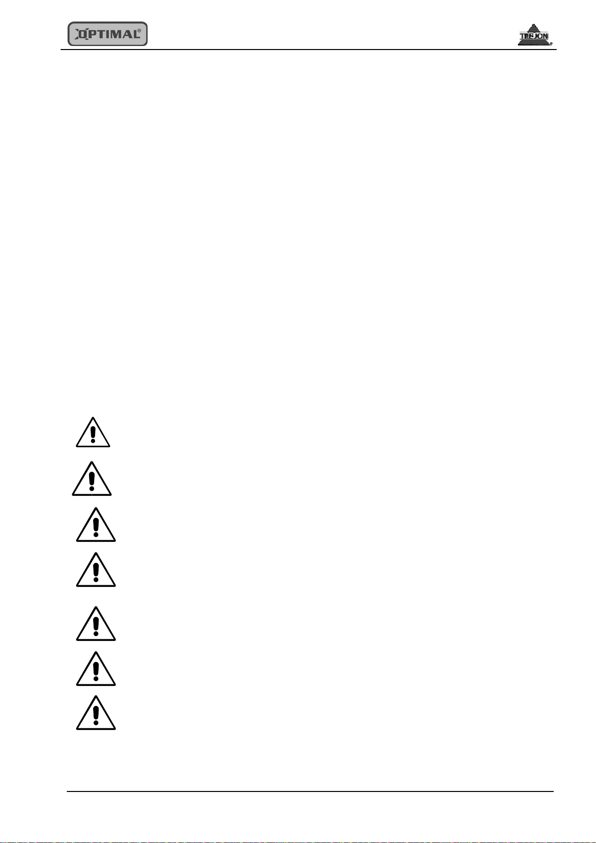
3 Technical description
The wings of the V-plough can be individually adjusted to pivot forwards and backwards: 30° with
model 150, 40° with models 210 and 240, and 35° with models 280 and 320, and see figure 1.
Thanks to this, the plough can be used in a pointed, diagonal, or Y position:
3.1 Attachment
The attachment is articulated for a horizontal tilt of up to 8°.
With normal driving the tilt should be 8°, see fig. 2, pos. A. Always supply details of the type of
mounting system or the suspension of the vehicle onto which the plough is to be installed when
ordering a V-plough.
3.2 Skid shoes
The V-plough is equipped with two skid shoes which can be set to different heights, see figure 2,
pos. B. During the season’s first ploughing, it is most suitable to set the skid shoes to a lower
position in order to avoid unnecessary wear on the scraper steels. After that the skid shoes should
be set to the same height as the scraper steels.
3.3 Scraper steels
The scraper steels are reversible. Each mouldboard is spring-loaded thus reducing the risk of
damage when an obstacle is hit.
The plough is delivered with scraper steels with bent-over edges (plough blades for pavements)
that reduce the risk of damage if a kerb is hit. These scraper steels can be reversed by shifting the
left or right mouldboard.
3.4 Hydraulics
The V-plough is powered by a double-acting hydraulic outlet connected to the tractor’s hydraulic
unit or the third or fourth hydraulic function of the loader. The plough is equipped with an
electric/hydraulic diagonal valve which make it possible to operate the wings individual or both
together parallel (in diagonal mode). The electric/hydraulic diagonal valve is operated by a hand
unit in tractor’s cabin.
Instruction manual OPTIMAL VP150-VP320 (0911)
trejonindustries.se
8
Fig. 1
Working width and total width at
different diagonal angels (measured
with same angel at both wings).
Fig. 2
4 Technical data
Modell 150 240 280 320
Width, mm 1500 2400 2800 3200
Full height, mm 840 990 990 990
Wing angle, degrees 30° 40° 35° 35°
Reversible scraper steels, pcs. 1+1 1+1 2+2 2+2
Weight, kg 240 470 580 660
Power unit Hydr./elec. Hydr./elec. Hydr. /elec. Hydr./elec.
Tension, Volt * 12 12 12 12
Max. hydraulic pressure, bars 175 175 175 175
* The plough is delivered with a 12-volt coil, which can be replaced with a 24-volt coil.
fig 3
A. Plough wing
B. Skid shoes
C. Mouldboard
D. Cylinder
E. Central piece
F. Skid spring
G. Connection frame
H. Machine plate
I. Warning sign
Instruction manual OPTIMAL VP150-VP320 (0911)
trejonindustries.se
9
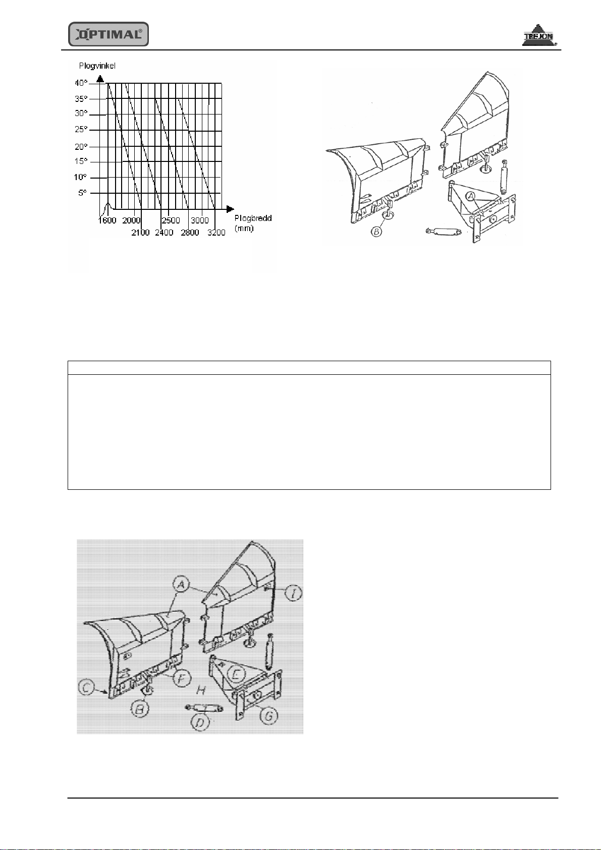
5 Installation
5.1 Lifting instructions
The V-plough is delivered strapped onto a Euro pallet.
There are two ways of lifting the plough from the pallet.
•directly onto the tractor’s attachment
•by a lifting tool such as a chain. Attach the lifting tool to the plough wings via the holes on
the supports, pos. A as well as around the hooks on the implement’s attachment arm,
pos. B.
Fig.4
P_030
CAUTION! ENSURE THAT NO ONE IS IN
THE RISK ZONE DURING LIFTING.

Instruction manual OPTIMAL VP150-VP320 (0911)
trejonindustries.se
10
5.2 Attaching the plough to the vehicle
The V-plough’s attachment arm fits the system of which details you supplied when ordering the
plough.
Mount the V-plough onto the tractor’s attachment as described in the tractor’s manual.
Ensure that the plough moves freely out of the tractor when attaching the plough.
5.3 Hydraulics
The V-plough is equipped with two 1.5-metre pressure hoses for attaching to the loader's third
hydraulic function or to another double-acting outlet on the tractor.
When in doubt about how to install the hydraulics, contact the tractor’s supplier.
The valves have a built-in shock function. If the hydraulic pressure inside the positive side of the
cylinder exceeds the set limits, the shock valve opens, releasing surplus pressure in an
accumulator.
Warning!
Modifications at ploughs hydraulic system and its connections will result in damages at
machine it hitting any firm obstacle.
5.4 Electricity
Fig. 5
Check that rated voltage at
coils agree with voltage from
tractor (a cover is removed at
the picture)
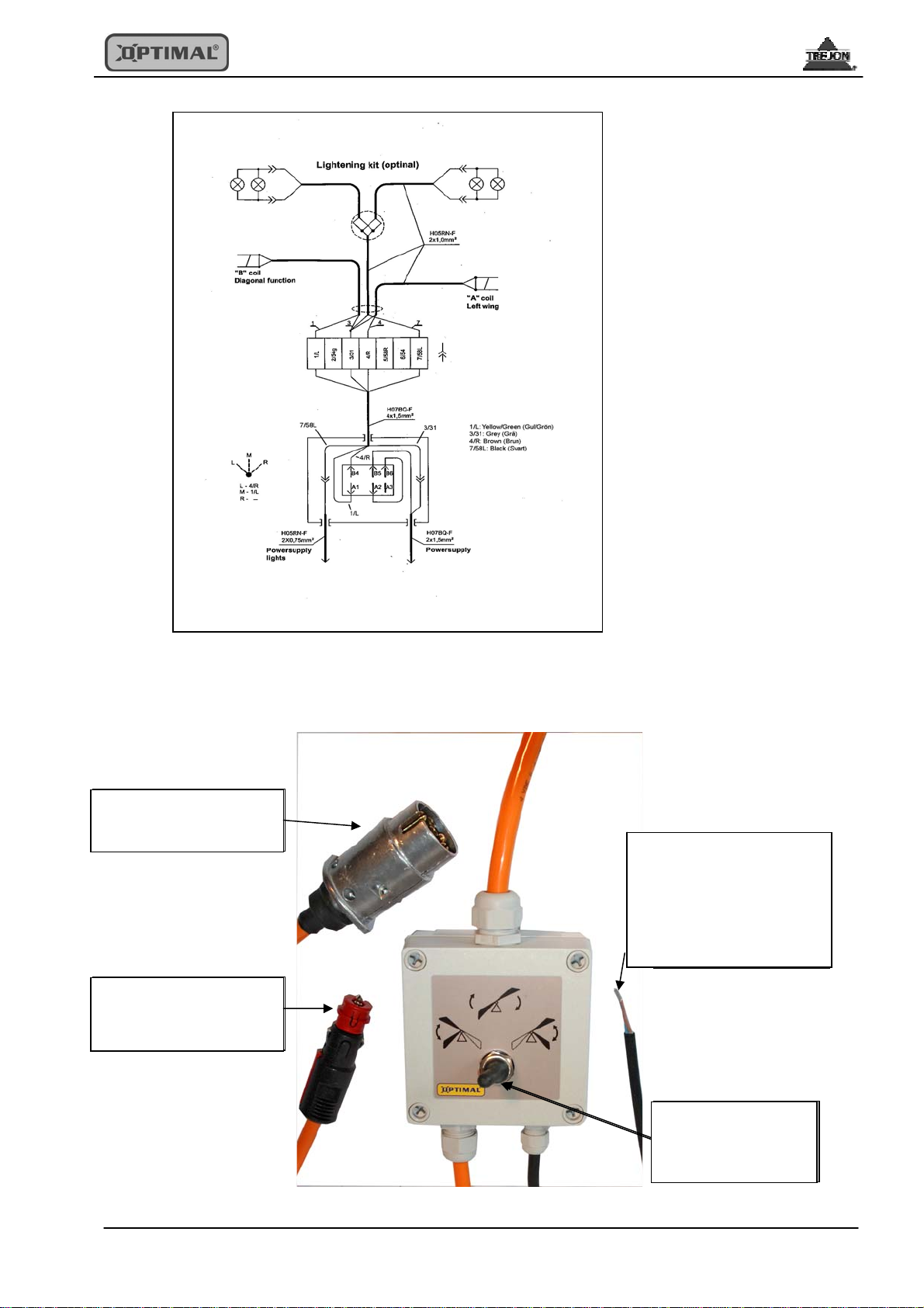
The V-plough is delivered with a hand unit and cable loom for connection to the plough and for
power supply (position lights is an option). Hand unit will be mounted in tractor’s cabin in a way
that makes it easy to operate.
Instruction manual OPTIMAL VP150-VP320 (0911)
trejonindustries.se
11
Fig.6 Electric diagram for VP-plough with diagonal valve
Power supply for
position lights (Option)
+12V (24V if lamps are
changed). Earth phase
is picked from ordinary
power supply.
Plug for connection to
the plough
Power supply 12V
(24V if coils are
changed)
Power supply for
position lights (Option)
+12V (24V if lamps are
changed). Earth phase
is picked from ordinary
power supply.
Switch for change
of operating
mode.
Fig.7
5.5 Hand unit
Plug for connection to
the plough
Switch for change
of operating
mode.
Power supply 12V
(24V if coils are
changed)

Instruction manual OPTIMAL VP150-VP320 (0911)
trejonindustries.se
12
Depending on the position of the switch at hand unit, plough is operated in following way with the
double acting hydraulic connection from tractor.
Right wing
Left wing
Diagonal mode, -left and right wing are moved simultaneously in different
direction.
6 Assemble
Caution!
Check that rated voltage at coils agree with voltage from tractor before use.
Diagonal valve is delivered with hand unit and cable loom for connection to the plough and for
power supply. Hand unit will be mounted in tractor’s cabin in a way that makes it easy to operate.
- Mount hand unit in a safe and easy operated place in tractor’s cabin.
- Fix the cable loom in a safe way along front loader/tractor.
- After connecting the plough, connect the plug from hand unit to plough. Wind remaining
cable, and fix it in a safe way.
- Connect power supply plug to outlet in tractor (fit both 12mm and 21mm outlet).

Instruction manual OPTIMAL VP150-VP320 (0911)
trejonindustries.se
13
7 Driving instructions
The OPTIMAL V-plough is intended for the ploughing of snow.
The plough can be used as:
9A POINTED PLOUGH for conventional ploughing.
9A Y-PLOUGH for pavements, street crossings and other areas where the collecting and
removing of snow is desirable.
9A DIAGONAL PLOUGH for the snowploughing of car parks, streets etc.
•By means of position of the switch at hand unit, the driver chooses which wing to move
(left, right or both in the diagonal mode) a and also commands the hydraulic oil flow via a
double-acting outlet.
•The V-plough is equipped with two skid shoes which can be set to different heights. Take
care that this skid shoes is clean and can move free. Skid shoes must be levelled to ground
before lowering plough, all to avoid damages on attachment device.
When ploughing in a pointed plough position, don’t drive with the cylinders close to
each other. (The accumulators cease to function if the cylinders are very close to each
other). Avoid running into posts, railings etc. The plough is equipped with a shock valve
that allows oil from the positive side of the cylinder to flow to the accumulator in case of
collision. A collision brings about increased strain on the plough. When the cylinder
reaches its lowest mechanical position there is no collision protection and the plough’s
frame can be damaged.
Be careful not to hit kerbs and traffic islands. The standard plough is supplied with
scraper steels for pavements which reduce the risk of damage to the machine.
NEVER DRIVE THE LOADER IN THE FLOATING POSITION!!
Don’t push the plough down as this puts unnecessary strain
on the implement and increases wear.
NEVER REVERSE WHEN THE PLOUGH IS LOWERED!!

Instruction manual OPTIMAL VP150-VP320 (0911)
trejonindustries.se
14
8 Service and maintenance
ENSURE THAT THE ENGINE IS TURNED OFF WHEN
PERFORMING MAINTENANCE
8.1 General maintenance
Check the screw joints every week.
Check the hydraulic hoses and hydraulic couplings at least once a week. If the components are
worn or cracked, they need to be replaced.
The hydraulic cylinder packing should only be changed by qualified personnel from the tractor
distributor network.
8.2 Lubrication
The lubricant nipples, 10 pieces, should be lubricated once or twice during the season. Use NLGI
2 oil with high EP characteristics.
8.3 Scraper steels
Turn the scraper steels before they start wearing out the plough's chassis. In order to turn the
outer scraper steels, shift right and left. Replace scraper steels when they are worn out.
Be careful not to get caught between the scraper steels and the ground when
replacing the scraper steels.
8.4 Long term storage
Lubricate all lubricant nipples (10 pieces) with consistent grease.
The skid shoes should be lubricated with spray oil.
Check all hoses, couplings and screw joints for wear and cracks. Replace damaged components.
Place the end caps on the hydraulic couplings.
Instruction manual OPTIMAL VP150-VP320 (0911)
trejonindustries.se
15
9 Spare parts
9.1 Use original spare parts
Your choice is between “original” or “copies”!
Price is often the deciding factor. A “cheap” choice may well be an expensive one in the end.
Some reasons to choose TREJON spare parts:
•Quality and fit.
•Reliability
•Longer service life and therefore better economics
•Guaranteed availability through the TREJON sales partners
The TREJON original spare parts are specifically made for this equipment. The fitting and/or use of
non-original parts and accessories may change the technical qualities of your equipment in a
negative way. The manufacturer does not give any guarantee for damages caused by using non-
original parts or accessories.
The guarantee does not cover arbitrary changes made on the equipment.
Contact the authorised dealer where you purchased the machine when you wish to order spare
parts or need other assistance.
When you are ordering spare parts, make sure you know the model, type and serial number of the
machine. See the plate on the chassis.

Instruction manual OPTIMAL VP150-VP320 (0911)
trejonindustries.se
16
10 Notes

Instruction manual OPTIMAL VP150-VP320 (0911)
trejonindustries.se
17
EC-Certificate of Conformity
conforming to EEC Directions 2006/42/EG
We TREJON FÖRSÄLJNING AB
(name of supplier)…..............................................................................................................................................………..
SE – 911 35 Vännäsby, Företagsvägen 9
…..............................................................................................................................................………..
(full address of company – where this concerns authorized agents within the Common Market, also state the company name and
manufacturer)
declare in sole responsibility, that the product
V-plough
OPTIMAL VP150, OPTIMAL VP240, OPTIMAL VP280, OPTIMAL VP320
…..............................................................................................................................................……………………
(make, model)
to which this certificate applies, conforms to the basic safety and health requirements of EEC
Directions 2006/42/EG,
(if applicable)
and to the other relevant EEC Directions.
— — —
…..............................................................................................................................................………..
(title and/or number and date of issue of the other EEC Directions)
(if applicable)
To effect correct application of the safety and health requirements stated in the EEC Directions,
the following standards and/or technical specifications were consulted:
EN ISO 12100-1 : 2003 EN ISO 12100-2 : 2003
…..............................................................................................................................................………..
(title and/or number and date of issue of standards and/or specifications)
Håkan Johansson
Vännäsby, 01.01.2009 Managing Director
......................................................... .............................................................................
(Place and date of issue) (Name and job function of authorized person)

Instruction manual OPTIMAL VP150-VP320 (0911)
trejonindustries.se
18
Warranty- / assignment certificate
Warranty terms
General about warranty -
The TREJON-warranty is limited by the conditions mentioned below and by the
specific warranty terms issued by the supplier. These terms are in such cases
attached to the operators manual for each machine.
Validity of warranty -
-
Where the machine is bought for private use, the warranty provided by TREJON is
valid for 12 months as of the date of purchase.
In case of commercial use for 3 months.
The warranty cover -
-
Damaged parts, which have broken down because of defective production
operations of materials in course of normal use of the machine.
The work-related expenditures, of the replacement of faulty spare part under the
warranty, are compensated according to the official price-list of TREJON.
TREJON may review the time for repair and adjust it to an average time of other
dealers to make similar repairs.
The warranty does not
cover
-
-
-
Transport costs applicable to the machine or the parts.
Travel costs.
Possible costs that have been caused by the failure of the machine.
-
-
-
-
If the machine has been modified by the owner.
Faults, which have been caused by the machine’s normal war and tear and are not
related to production faults.
Inexperienced use or use of spare parts, which are not original.
The warranty is not applicable to parts which are subject to wear, for example
hoses, sealing, oil, belts, batteries, chains, knifes etc.
Warranty procedures -
- Before you start large warranty works, contact TREJON AB.
In case you want the warranty to be valid, the TREJON warranty claim must be
completed and returned to TREJON AB no later than within 3 weeks after the repair
have been carried out. Return of exchanged parts should only be sent on demand.
ATTENTION!
The warranty becomes valid after the WARRANTY / ASSIGNMENT CERTIFICATE
has been completed and returned to TREJON within 14 days after the date of
purchase.
Assignment certificate:
The buyer of the machine hereby verifies with his/her signature of having admitted the manual and studied it and
been provided with the necessary driving instructions and passed after-delivery control.
PLEASE FILL IN!
Product: Serialno:
Salesman:
Company:
Signature of salesman:
Date of purchase:
Name of
buyer:
Telephone:
Address:
Postcode:
City:
Country:
Date:
Signature of buyer:

Instruction manual OPTIMAL VP150-VP320 (0911)
trejonindustries.se
19
TREJON AB reserves the right to change or to improve shown models using technical or
commercial reasons, without demands to carry out the same improvements on equipment already
delivered. Pictures in the manual do not necessarily show the equipment as delivered.
Technical data, weights and measures are without obligation. Reservation for faults.
© 2009 Trejon AB, Sweden
Copying, translation and excerpts are only permitted with a written permit from TREJON AB,
Företagsvägen 9, SE – 911 35 Vännäsby.

TREJON AB
Företagsvägen 9
SE-911 35 VÄNNÄSBY
SWEDEN
Tel: + 46 (0)935 39 900
Fax: + 46
(
0
)
935 39 919
This manual suits for next models
4
Table of contents


