Polaris 2882798 User manual

APPLICATION
Verify accessory fitment at Polaris.com.
BEFORE YOU BEGIN
Read these instructions and check to be sure all parts and tools are accounted for. Please retain these
installation instructions for future reference and parts ordering information.
KIT CONTENTS
This Kit includes:
REF QTY PART DESCRIPTION PART NUMBER
1 1 1500 Winch Assembly 1023692
2 1 Winch Carrier 1023484
3 1 Hitch Receiver 1023486
4 1 Battery Harness - Power 4017356
51 Winch Harness - Jumper 4017355
6 1 Stop Bumper 5416562
7 1 Winch Hook 2411836
8 1 Storage Bag 2688505
Instr 9927951 Rev 02 2017-11 Page 1 of 12
P/N 2882798
INTEGRATED1500LB WINCH KIT

Instr 9927951 Rev 02 2017-11 Page 2 of 12
REF QTY PART DESCRIPTION PART NUMBER
9 1 Winch Remote - Wired (included in winch assembly) -
10 1 Winch Remote - Wireless 4017125
11 2 Hitch Pin Assembly 1023975
12 4 Screw - M8 x 1.25 x 25 7520877
13 2 Screw - M6 x 1.0 x 40 7518579
14 2 Nut - M6 x 1.0 7546703
15 2 Nut - M8 x 1.25 7547454
16 2 Screw - M8 x 1.25 x 30 7518953
17 3 Rivet - 3/16” 7661637
18 2 Well Nut - M5 x 0.8 7547354
19 2 Bushing - Battery Cable 5141925
20 2 Screw - M5 x 0.8 x 40 7520876
21 1 Battery Bolt Kit (not shown) 2201357
1 Instructions 9927951
TOOLS REQUIRED
• Safety Glasses
• Drill
• Drill Bit: (specify size)
• Pop Rivet Puller
• Socket Set, Metric
• Socket Set, Torx®Bit
• Torque Wrench
• Wrench Set, Metric
IMPORTANT
Your Integrated1500lb Winch Kit is exclusively designed for your vehicle. Please read the installation
instructions thoroughly before beginning. Installation is easier if the vehicle is clean and free of debris. For your
safety, and to ensure a satisfactory installation, perform all installation steps correctly in the sequence shown.
ASSEMBLY TIME
Approximately 48 minutes

Instr 9927951 Rev 02 2017-11 Page 3 of 12
INSTALLATION INSTRUCTIONS
NOTE
Any previously installed accessories that may
interfere with the installation of the Integrated 1500lb
Winch kit will need to be removed from the vehicle
and set aside for later reinstallation before
proceeding with this installation. See the installation
manuals that accompanied previously installed
accessory kits for details on removal and
reinstallation.
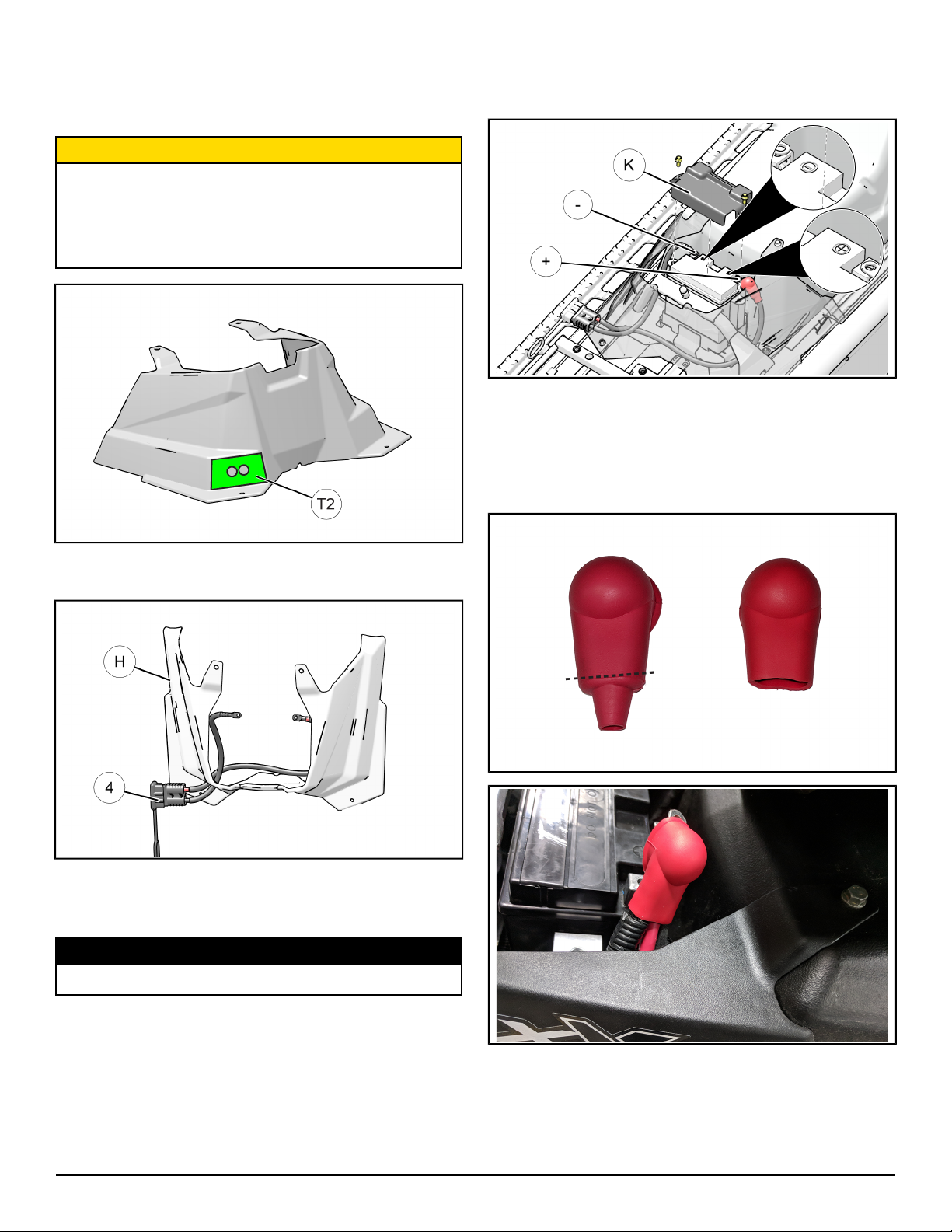
1. Remove the rear cargo platform Dbefore drilling
holes to avoid damage to the vehicle. To do so,
remove two screws Afrom tail light Band
remove tail light assembly by unplugging tail light
from harness. Set aside for later reinstallation.
Then remove the ten screws Csecuring the rear
cargo platform to the vehicle.
2. Carefully cut out hole location templates for steps
3 & 5 from the last page of this instruction. Verify
templates were printed to proper scale by using a
ruler or tape measure to verify REFERENCE
DIMENSION is exactly 4 inches.
IMPORTANT
If your measurement is not exactly 4 inches, then
reprint template pages from electronic file using print
setting “Actual Size” (not “Fit”) to obtain proper 1:1
scale. Electronic file available from your Authorized
Polaris Dealer.
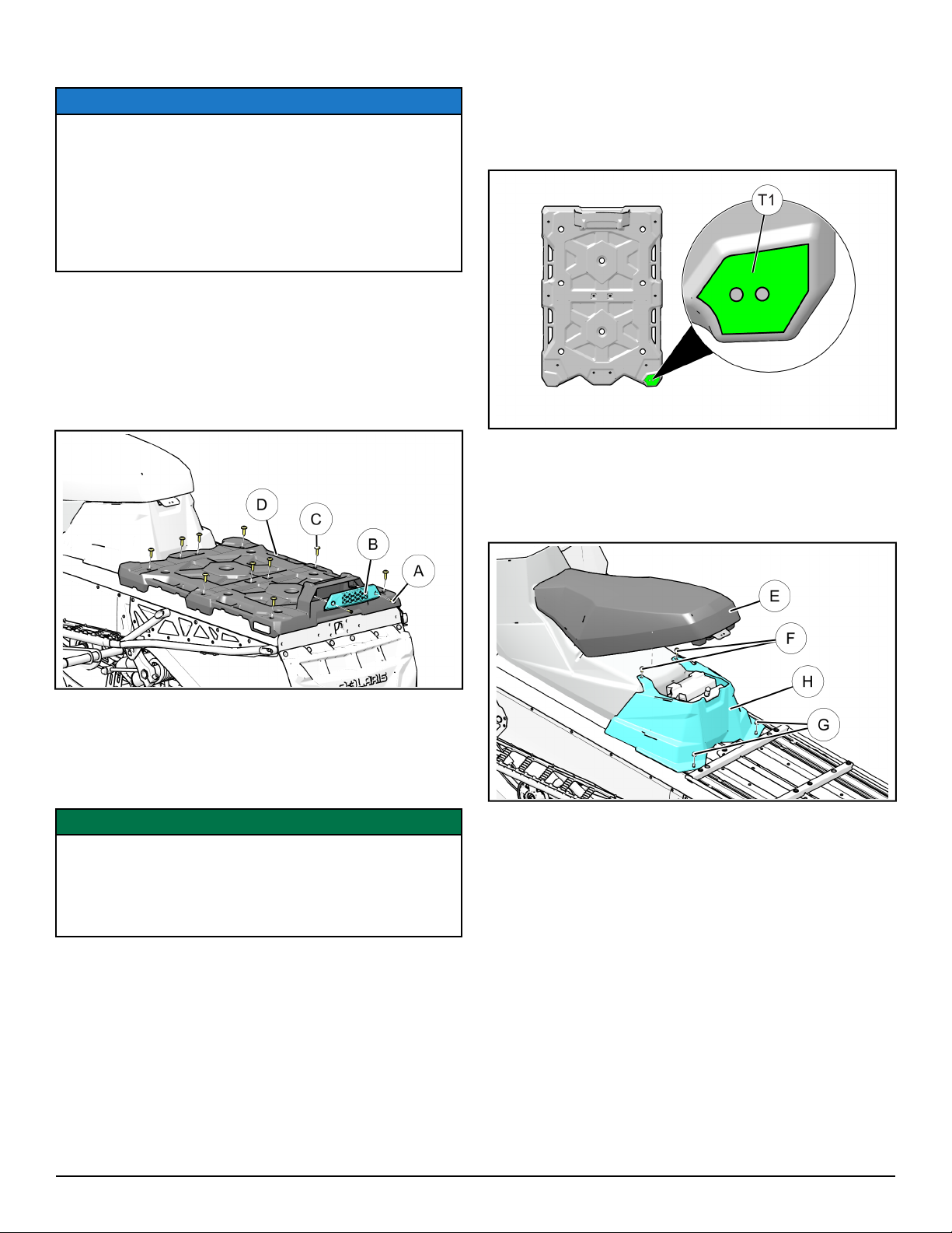
3. Place rear cargo platform template (T1) into
position as shown and mark the location of holes
to be drilled. Once marked, drill the required 3/8”
holes in the rear cargo platform.
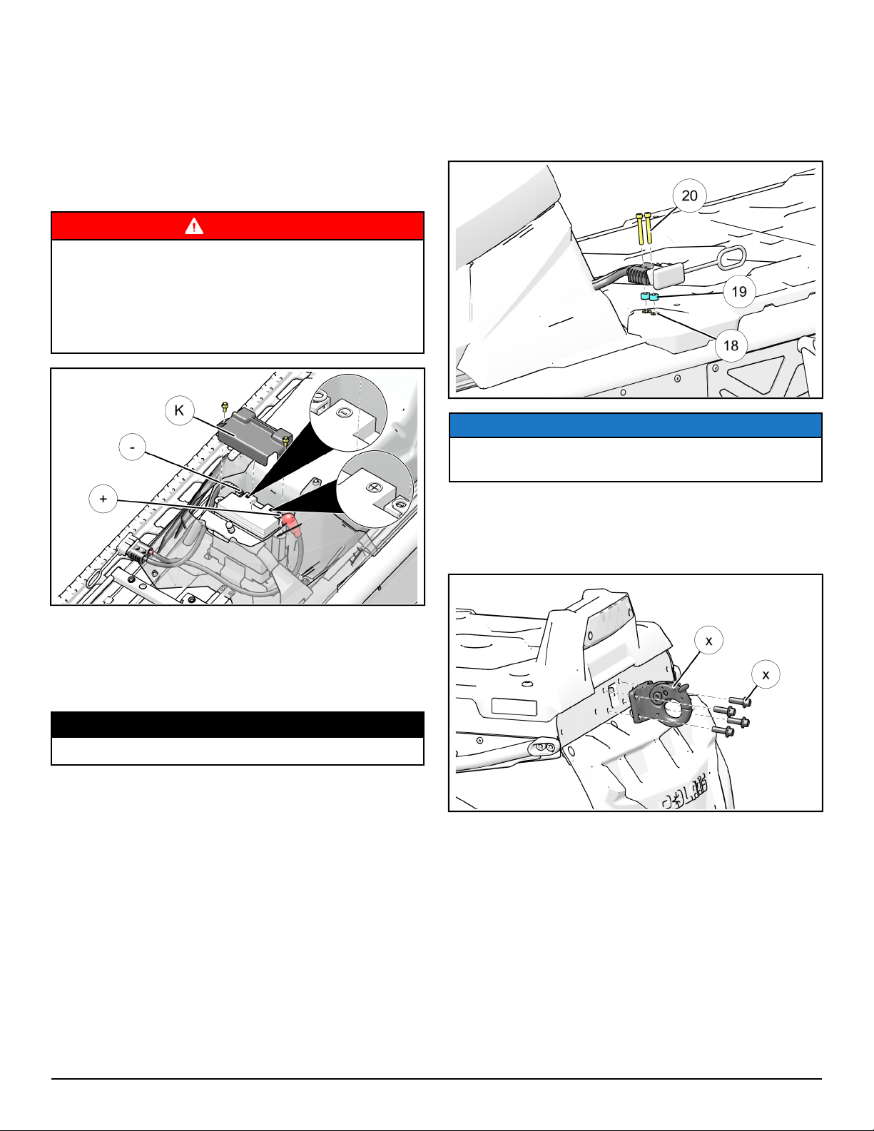
4. Next remove seat Eto gain access to the
fasteners securing the rear tank cover Hin place
and remove fasteners Fand Gto remove rear
tank cover Hbefore drilling. Retain all fasteners
for reinstallation.

Instr 9927951 Rev 02 2017-11 Page 4 of 12
5. Place rear tank cover template into position as
shown and mark the location of the holes. Once
marked, drill the required 1/2” holes in the rear
tank cover.
CAUTION
DO NOT attempt to drill holes in rear tank cover
without removing from vehicle as the battery is in
close proximity to the inside of the cover. Failure to
remove the cover before drilling may result in
personal injury or damage to equipment.
6. Route battery harness cables rthrough holes in
rear tank cover Has shown.
7. Reinstall rear tank cover and torque all four rear
tank cover fasteners to specification provided
below.
TORQUE
35 In. Lbs (4 Nm)
8. Remove battery cover Kand disconnect black
negative (-) cable from battery FIRST, then
disconnect red positive (+) cable from battery.
9. 9. Remove existing red positive (+) battery cable
cover and cut as indicated by the dotted line in the
image below to allow both the existing red positive
(+) battery cable along with the new red positive
(+) winch harness cable (and any other required
red positive (+) cables) to be routed as shown.

Instr 9927951 Rev 02 2017-11 Page 5 of 12
10.Install red positive (+) battery harness cable along
with all other required red positive (+) cables with
new longer battery bolt and threaded battery post
block that was provided with your kit to the positive
(+) battery terminal. Then install the black negative
(-) battery harness cable and all other required
black negative (-) cables to the negative (-) battery
post with new provided battery connection
hardware.
WARNING
When BOTH battery cables are disconnected
ALWAYS reconnect AND tighten red positive (+)
battery cable to battery FIRST. Failure to comply will
result in a high current electrical arc, and may result
in battery explosion, if tool touches grounded frame.
Death or serious personal injury may occur.
Once all cables are securely fastened to their
respective terminals reinstall the battery cover K.
11. Reinstall rear cargo platform and torque all ten
rear cargo platform fasteners to specifications
listed below.
TORQUE
8.5 Ft. Lbs (12 Nm)
12.Secure the electrical connector portion of the
battery harness to the rear cargo platform by fully
inserting the well nuts linto the previously drilled
mounting holes then placing spacers 1( into
position as shown and securing the connector
using provided bolts 2).
NOTE
If Receiver Hitch Kit PN 2882795 has been
previously installed skip steps 12-13.
13.Next you will need to remove the standard rear
hitch Lfrom the vehicle as shown. Discard
fasteners as they will be replaced with fasteners
provided with the winch kit.

Instr 9927951 Rev 02 2017-11 Page 6 of 12
14.Install the supplied receiver hitch ewith provided
fasteners d. Torque to specification provided
below.
TORQUE
20 Ft. Lbs (27 Nm)
15.Next, remove the two indicated rivets Mfrom the
right hand running board using a drill and 1/4” drill
bit.
16.Place winch carrier winto position and secure in
place using the provided fasteners f/g.
17.Using a drill and 3/16” drill bit transfer drill the
three indicated mounting hole locations N. After
drilling, install provided rivets kwith rivet puller to
secure to chassis.

Instr 9927951 Rev 02 2017-11 Page 7 of 12
18.Transfer drill the upper two indicated mounting
hole locations Pusing a drill and 11/32” (9mm)
drill bit. After drilling secure with provided
fasteners hand jbeing sure to insert the bolts
from the inside to the outside as shown.
IMPORTANT
Ensure the locking nuts are on the outside of the
tunnel. Track damage may occur if fasteners are
installed opposite as shown.
19.Install the stop bumper yand winch hook uonto
the winch rope as shown by first threading the
winch rope through the stop puck and then
attaching the winch hook onto the end of the rope
using the clevis Uand cotter pin V.
20.Replace seat and any other previously removed
accessories.
21.Your Integrated Winch Kit comes with a Lock and
Ride Bag to store the winch accessories in. If you
do not have a rear cargo box place the winch bag
onto the rear cargo rack and line up the lock and
ride anchors with the front two lock and ride holes.
Insert them fully into the holes and cam over the
lock and rides to secure the bag into position.
If you do have the rear cargo box, the lid of the
cargo box is specifically designed to hold the bag
and its contents. Simply open the cargo box lid
and insert the bag in the opening on the lid.
22.Check to ensure all tools are accounted for and all
steps have been completed as required.

Instr 9927951 Rev 02 2017-11 Page 8 of 12
OPERATION
IMPORTANT
The winch should always be transported in the
carrier wto avoid damage to the vehicle and/or
winch assembly. ALWAYS secure it in place with the
provided hitch pin smaking sure the R-Pin Sof the
hitch pin assembly is fully seated and securely
holding the pin in place before transporting the
winch.
To use the integrated winchs, remove it from the
carrier and place it into the receiver hitch eon the
rear of the vehicle. ALWAYS secure it in place with the
provided hitch pin smaking sure the R-Pin Sof the
hitch pin assembly is fully seated and securely holding
the pin in place before using the winch.
GEAR SELECTION
WARNING
Attempting to shift the winch while the rope is under
tension is dangerous and can result in injuries or
death. Make sure the winch rope is not in tension
before shifting the winch between gears.
Your winch is equipped with two different gear
settings. It will either be in the “LOCK” position or the
“FREE” position.
The free position is designed to allow you to “free-
spool” the winch when you want to pull the rope or
cable out faster than what it would allow while in the
lock position.
To shift between the free position and the lock position
simply turn the shifting knob located on the side of the
winch either clockwise or counter-clockwise
depending on the desired mode.

Instr 9927951 Rev 02 2017-11 Page 9 of 12
WIRELESS REMOTE OPERATION
• When properly installed, the wireless remote will
allow you to operate the winch from on or off the
vehicle.
• To use the wireless remote, hold the small "On/Off"
button for three seconds or until the LED light on the
remote turns on. If the vehicle is on so that the
winch is receiving power, the wireless remote
should operate the winch as if you were using the
manual winch switch. If the remote is not operating
properly, see the troubleshooting information at the
end of the instructions.
• The remote will automatically turn itself off after 30
seconds of inactivity. You will therefore need to turn
the remote back on if it has been more than 30
seconds since prior use.
• To manually turn off the remote, hold the small "On/
Off" button for 3 seconds or until the LED light turns
off.
• See the illustration below for proper wireless remote
operation.
WIRED REMOTE OPERATION
• To use the wired remote make sure it is connected
to the winch. Once connected, the wired remote
operates much like the wireless remote and will
allow you to operate the winch from on or off the
vehicle.
• To use the wired remote, depress and hold the
“OUT” button to extend cable. To recover cable,
depress and hold the “IN” button. If the wired
remote is not operating properly, see the
troubleshooting information at the end of the
instructions.

Instr 9927951 Rev 02 2017-11 Page 10 of 12
TROUBLESHOOTING
If your winch is not functioning properly, below is a short guide that can help you diagnose and correct the
problem.
SYMPTOM POSSIBLE CAUSES RECOMMENDED SOLUTION
Dead vehicle
battery
Incorrect, damaged, or
corroded electrical
connections
Verify all winch electrical connections are per instruction
manual and free of damage and/or corrosion.
Winch will not
operate
Contactor not receiving
power
Ensure winch harness jumper cable is properly connected.
Wireless remote not
powered on
Turn wireless remote on.
Incorrect, damaged, or
corroded electrical
connections
Verify all winch electrical connections are per instruction
manual and free of damage and/or corrosion.
Winch makes noise
but rope/cable does
not move
Contactor powered, but
not winch
If clicking sound is heard when winch control button is
depressed, but winch motor is silent, then verify electrical
connections between winch and contactor are free of damage
and/or corrosion.
If winch makes noise but does not move, verify winch is in
gear.
If winch is in gear, but winch still does not move, have a
dealer inspect the winch.
Winch operates too
slowly
Winch is improperly
loaded
Verify rope/cable is not binding on spool or fairlead.
Winch will not
change gears
Rope/cable is under
load
Changing gears while under load is intentionally difficult to
prevent accidental operation, which could lead to personal
injury or winch failure. Ensure rope/cable is under no tension,
and rope/cable is not binding on spool or fairlead. Briefly
operate winch, then attempt to shift again.
FEEDBACK FORM
A feedback form has been created for the installer to provide any comments, questions
or concerns about the installation instructions. The form is viewable on mobile devices
by scanning the QR code or by clicking HERE if viewing on a PC.
FEEDBACK FORM

Instr 9927951 Rev 02 2017-11 Page 11 of 12
THIS PAGE INTENTIONALLY LEFT BLANK

Instr 9927951 Rev 02 2017-11 Page 12 of 12
TEMPLATE PAGE
4.00
REFERENCE DIMENSION (INCHES)
T1
T2
Table of contents
Other Polaris Snow Blower Accessories manuals