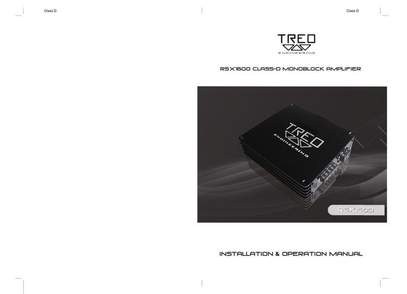
Treo Engineering SSX750.1 User manual

OWNER'S MANUAL
SSX750.1 / SSX1500.1
SSX125.2 / SSX250.2 / SSX75.4

- 2 -
TREO ENGINEERING
SSX750.1 & SSX1500.1
SSX125.2, SSX250.2 & SSX75.4
TABLE OF CONTENTS
3INTRODUCTION
3FEATURES
3WARNING
4PLANNING YOUR SYSTEM
5CHOOSING MOUNTING LOCATION
6WIRING CONNECTION
7-8 INTERNAL CONFIGURATION (SSX750.2 & SSX1500.1)
8-10 INTERNAL CONFIGURATION (SSX125.2, SSX250.2 & SSX75.4)
11-13 SPEAKER CONNECTION (SSX750.2 & SSX1500.1)
14-15 SPEAKER CONNECTION (SSX125.2 & SSX250.2)
16-17 SPEAKER CONNECTION (SSX75.4)
18 TROUBLE SHOOTING GUIDE
19 SPECIFICATIONS
20 WARNING
21 WARRANTY

INTRODUCTION
TREO ENGINEERING amplifiers provide high-performance sound amplification for
yourmobile audio equipment. Its versatility enables compatibility with optional
equalizer,crossover networks, and other audio processors in a customized system.
The multi-mode bridging capabilities allow flexibility in powering several different
speakerconfigurations.
To achieve optimum performance, it is highly recommended that you read this
owner's manual in its entirety before beginning installation. This amplifier is very full-
featured and includes advanced features you may not be familiar with. If you have
any questions after reading this manual we suggest you contact your TREO dealer for
help.
FEATURES
RCA Input & Output
Selectable Crossover HPF/FULL/LPF (SSX125.2, SSX250.2 & SSX75.4)
Adjustable Input Sensitivity 0.2-5.5V
0dB-12dB TREO Bass Boost with variable center frequency 30-800Hz (SSX125.2, SSX250.2
& SSX75.4)
0dB-24dB TREO Bass Boost (SSX750.1 & SSX1500.1)
Selectable Sub-Sonic Filter (SSX750.1 & SSX1500.1)
2 Ohm Stereo / 4 Ohm Mono Stable Operation (SSX125.2, SSX250.2 & SSX75.4)
Pulse Width Modulation MOSFET Power Supply
Soft-Delayed Remote Turn-On
Dual Color LED Indicator
Low-Profile Heat Sink Design
Nickel-Plated Terminals
Protection Circuitry:
Thermal Protection Circuit
Short Protection Circuit
Over Load Protection Circuit
WARNING
High-powered audio systems in a vehicle are capable of generating extremely high
levels of sound pressure. Continued exposure to excessive sound pressure levels may
cause hearing damage or hearing loss. Operation of a motor vehicle while listening
to audio equipment at sound pressure levels may impair your ability to hear external
sounds such as horns, warning signals, or emergency vehicles. This constitutes a
potential traffic hazard. In the interest of safety TREO ENGINEERING recommends
listening at lower volume levels while driving.
- 3 -

- 4 -
PLANNING YOUR SYSTEM
Before beginning the installation, consider the following:
1. Do you plan to add additional mobile electronics equipment in the future?
If you plan to expand your system by adding other components sometime in the
future, ensure adequate space is left and cooling requirements are met.
2. Should you use high or low level inputs?
Your Amplifier has been designed to accept Low-Level(Pre-Amp outputs from your
radio) signal source. If your radio/source is equipped with Pre-Amp outputs, it is possible
to utilize them todrive the Amplifier and connecting(Amplifier) to the 2 rear speakers.
Then, use thebuilt-in power of your radio to drive the 2 front speakers.
3. Are your components matched?
The RMS power rating of your speaker(s) must be equal or greater than the RMS
power rating of your amplifier. Your speaker(s) also must be 2 - 8 Ohms impedance
for stable amplifier operation. Impedance information is normally printed on the
speaker basket or magnet.
4. Where will the amplifier be installed?
Consider both the length of your leads, and routing when determining the mounting
location. It is best to run power and RCA wiring on opposite sides of the vehicle to
prevent induced noise. Pre-amp input jacks require a length of high quality shielded
male to male RCA patch cord.

- 5 -
CHOOSING MOUNTING LOCATIONS
The location of your amplifier will depend on several important issues. Due to the low-
profile size of TREO ENGINEERING amplifiers, there are many possible installation
locations that will yield excellent amplifier performance and reliability. Always mount
the amplifier in a place that protects the amplifier from the elements such as water,
ice, and road debris. Mount the amplifier on a stable, flat mounting surface. As with
any amplifier, there are several possible mounting locations and configurations that
can be used. We will cover the most common situations.
PASSENGER COMPARTMENT
MOUNTING
If you are going to mount the amplifier
in the passenger compartment, make
sure you leave adequate room for
amplifier ventilation. TREO ENGINEERING
amplifiers rely on ventilation for proper
cooling. TREO ENGINEERING amplifiers
have been designed to make under seat
mounting possible,. when mounting your
amplifier under a seat or similar area,
keep a minimum of 1" of clearance in all
directions around the amplifier for
adequate cooling.
TRUNK COMPARTMENT MOUNTING
Mounting the amplifier in the trunk
provides excellent performance as long
as you do not mount the amplifier upside
down or restrict the airflow around the
heatsink of the amplifier. For optimal
results, mount the amplifier with the cooling fins in the vertical position. This type of
mounting will yield the best cooling due to the convection effect of the amplifier
chassis.
ENGINE COMPARTMENT MOUNTING
Do NOT mount the amplifier in the engine compartment. TREO ENGINEERING amplifiers
were not designed to endure the harsh conditions present in the engine ompartment.
- 5 -

- 6 -
WIRING CONNECTIONS
CONNECTING THE POWER (Fig. 1)
AS A PRECAUTION, YOU SHOULD ALWAYS DISCONNECT THE VEHICLE'S BATTERY BEFORE
CONNECTING TO THE +12 VOLT SUPPLY WIRING.
4AWG wire is recommended for both the power and ground wires. Use thicker wire
for multiple amplifiers.
16-22 AWG wire is recommended for the remote turn-on wire. Both types are
available at most Mobile Audio Dealers or Installations Shops.
(1) Ground :To Vehicle Body
To avoid unwanted noise caused by ground loops, it is essential that the amplifier be
grounded to a clean, bare, metal surface of the vehicle's body. Use 4 AWG wire
terminated with a ring terminal for this connection. Ground wire should not be
extended any longer than three feet (one meter).
(2) +12 Volt(Fused) Constant Power:To Battery (+)
Due to the current requirements of the amplifier amplifier, this connection should be
made directly to the positive (+) terminal of the battery. To prevent a possible
electrical fire, install an in-line fuse holder (not included) as close to the positive (+)
terminal of the battery as possible. Use a fuse (not included) with an ampere rating
below.
SSX125.2: 100A SSX750.1: 150A
SSX250.2: 150A SSX1500.1: 250A
SSX75.4: 100A
(3) Remote Turn-On Input: To Remote Lead or Power Antenna output of Car Stereo
This Amplifier is "turned on" remotely when the vehicle's stereo is on. If your radio does
not have a +12 volt output lead when the radio is turned on, the "REMOTE" terminal
on the amplifier can be connected to vehicle's accessory circuit that is live when the
vehicle's ignition is on.
Fig. 1

SUBSONIC Filter
Frequency adjustment control for the subsonic (HPF) filter
adjustable 15-50Hz.
- 7 -
INTERNAL CONFIGURATION [SSX750.1/SSX1500.1]
INPUT GAIN CONTROL
The input sensitivity adjustments range from 0.2 to 5.5V to easily
integrate with any quality aftermarket source unit.
LINE OUTPUT
T-BASS
The Aux outputs offer easy system expansion.
Routing signal from a source unit, pre-amplifier or equalizer is a
matter of routing RCA' s into the RCA inputs and out through the
line-level outputs to the next amplifier.
Varies from 0 dB to +24dB of boost.
Controls gain level for T-Bass Boost.
LPF Frequency adjustment control for the LPF filter adjustable 35-
250Hz.

- 8 -
INTERNAL CONFIGURATION [SSX125.2/SSX250.2/SSX75.4]
LINE OUT X- OVER HIGH PASS
This crossover does not effect the speaker output of the
amplifier. This crossover only filters the line output of the
amplifier.
This filter is variable 30-4000Hz.
LINE OUT X- OVER FULL-PASS
When the switch is in the "HP" position the line output signal
is filtered with a high pass crossover at the selected
frequency. When the switch is in the "Full" position the
crossover for the line output is bypassed. When the switch is
in the "LP" position the line output is filtered with a lowpass
crossover at the selected frequency.
INPUT GAIN CONTROL
LINE OUT X- OVER LOW PASS
This crossover does not effect the speaker output of the
amplifier. This crossover only filters the line output of the
amplifier.
This filter is variable 30-4000Hz.
The input sensitivity of these adjustments range
from 0.2V up to 5.5Vrms to easily integrate with
any quality aftermarket source unit.
BRIDGE MODE
- Servant Mode: To be switched on when linking one
amplifier with another amplifier of same model.
- Master Mode: To be switched on when only using a
single amplifier.
Master mode is the default for SSX750.1 & SSX1500.1

- 9 -
When the switch is in the position ON the high-pass
crossover is active.
The high-pass crossover is continuously variable
push multiplier button ON( x 10 ) : 200 ~ 5000Hz
push multiplier button OFF( x 1 ) : 20 ~ 500Hz
When the switch is in the position ON the low-pass
crossover is active.
the low-pass crossover is continuously variable.
push multiplier button ON( x 10 ) : 500 ~ 9000Hz
push multiplier button OFF( x 1 ) : 50 ~ 900Hz
In many car audio systems placement of the subwoofers can
cause them to be out of phase with the rest of the system. This
may cause poor subwoofer performance due to varying arrival
times. To eliminate this the SSX125.2, SSX250.2 & SSX75.4
incorporates 0 ~ 180 variable phase correction. By playing low
frequency music and experimenting with the subwoofer phasing
better sound quality and bass imaging may be obtained.
X- OVER HIGH-PASS
AUXILIARY OUTPUT
PHASE
T-BASS
TREO ENGINEERING amplifiers offer T-BASS circuitry with
variable bass gain and center frequency T-Bass gain is
adjustable 0-12dB. T-Bass center frequency is variable 30-
800Hz.
X- OVER LOW-PASS
The Auxiliary outputs offer easy system expansion.
Routing signal from a source unit, pre-amplifier or equalizer
is a matter of routing RCAs into the RCA inputs and out the
AUX outputs to the next amplifier .

- 10 -
INPUT MODE[SSX75.4]

- 11 -
MONO CHANNEL CONFIGURATION FOR SSX750.1/SSX1500.1
1-4 ohms
SUB WOOFER
*Lowest Recommended Impedance is 1-4ohm Mono
*RCA Inputs are connected to both Left and Right channels
*Gain controls to be set to match input source
*Line Output can be configured for high-pass, low-pass or full range
operation

- 12 -
SUMMED BRIDGED CONFIGURATION FOR SSX750.1
*Lowest recommended impedance is 2-4 Ohm mono
*RCA Inputs are connected to both Left and Right channels
*Gain control to be set to match input source.
*Line Output configured summed bridged which is ideal for subwoofer
applications

- 13 -
SUMMED BRIDGED CONFIGURATION FOR SSX1500.1
*Lowest recommended impedance is 2-4 Ohm mono
*RCA Inputs are connected to both Left and Right channels
*Gain control to be set to match input source.
*Line Output configured summed bridged which is ideal for subwoofer
applications

- 14 -
TWO CHANNEL STEREO CONFIGURATION FOR
SSX125.2/SSX250.2
*Lowest Recommended Impedance is 2ohm stereo
*RCA Inputs are connected to both Left and Right channels
*Gain controls to be set to match input source
*Line Output configured for stereo operation

- 15 -
TWO CHANNEL BRIDGE MODE CONFIGURATION FOR
SSX125.2/SSX250.2
*Lowest recommended impedance is 4ohm bridged mono
*RCA Inputs are connected to both left & right channels
*Line Output is configured summed bridged which is ideal for subwoofer
applications

- 16 -
FOUR CHANNEL STEREO CONFIGURATION FOR SSX75.4
*Lowest Recommended Impedance is 2ohm Stereo
*RCA Inputs are connected to both Left and Right channels
*Gain controls to be set match input source
*Line Output configured for stereo operation

- 17 -
FOUR CHANNEL BRIDGE MODE CONFIGURATION FOR SSX75.4
*Lowest recommended impedance is 4ohm bridged mono
*RCA Inputs are connected to both left & right channels
*Line Output is configured summed bridged which is ideal for subwoofer
applications

Check fuses in amplifier.
Be sure Turn-on lead is connected
Repair power wire or connections
Check connections to radio
Check fuse
Inspect for short circuit or an
open connection.
Reverse Left and Right
RCA inputs to determine if it is
occurring before the amp.
Check Tuner/Deck volume level.
Clean contacts on fuse holders.
Be sure proper speaker to ensure
impedance recommendations
are observed.
(If you use an ohmmeter to
Check speaker resistance,
please remember that DC
resistance and AC impedance
may not be the same.)
NO SOUND
AMP NOT
SWITCHING
ON
NO SOUND
IN ONE
CHANNEL
AMP
TURNING
OFF
MEDIUM/
HIGH
VOLUME
SYMPTOMS CHECK POINTS CURE
- 18 -
TROUBLE SHOOTING GUIDE
Is the power
LED illuminated?
No power to power wire
No power to remote
wire with receiver on
Fuse broken
Check Speaker Leads
Check Audio Leads
Check speaker load
impedance

- 19 -
SPECIFICATIONS
SPECIFICATIONS & MODEL#
MAXIMUM POWER OUTPUT
POWER OUTPUT @1Ohm
POWER OUTPUT @2Ohm
THD @2Ohm
POWER OUTPUT @4Ohm
THD @4Ohm
BRIDGED POWER
FREQUENCY RESPONSE 1.0dB
HPF
LPF
SUBSONIC FILTER
T-BASS
PHASE
ADJUSTABLE SENSITIVITY RANGE
INPUT IMPEDANCE (LOW LEVEL)
DIMENSION (D x W x H mm)
SSX750.1
2000W
750W
500W
0.1%
300W
0.1%
-
15Hz~250Hz
-
35Hz~250Hz
15Hz~50Hz
0 ~ 24dB
-
0.2V ~ 5.5V
10K Ohms
323X282X55
SSX1500.1
4000W
1500W
1000W
0.1%
600W
0.1%
-
15Hz~250Hz
-
35Hz~250Hz
15Hz~50Hz
0 ~ 24dB
-
0.2V ~ 5.5V
10K Ohms
489X282X55
SSX125.2
1000W
-
2 X 250W
0.1%
2 X 125W
0.1%
1 X 500W
10Hz~50Hz
20Hz ~ 5KHz
50Hz~9KHz
-
0 ~ 12dB
0 ~ 180
0.2V ~ 5.5V
10K Ohms
379X282X55
SSX250.2
2000W
-
2 X 500W
0.1%
2 X 250W
0.1%
1 X 1000W
10Hz~50Hz
20Hz ~ 5KHz
50Hz~9KHz
-
0 ~ 12dB
0 ~ 180
0.2V ~ 5.5V
10K Ohms
489X282X55
SSX75.4
1200W
-
4 X 100W
0.1%
4 X 50W
0.1%
2 X 200W
10Hz~50Hz
20Hz ~ 5KHz
50Hz~9KHz
-
0 ~ 12dB
0 ~ 180
0.2V ~ 5.5V
10K Ohms
429X282X55
FEATURES AND SPECIFICATIONS ARE SUBJECT TO CHANGE WITHOUT NOTICE.

- 20 -
WARNINGS
Investigate the layout of your automobile through before drilling or cutting
any holes. Take care when you work near the gas tanks, lines, and
electrical wiring. Don't use power amplifier without securelymounting
it. Attach this system securely to the automobile to prevent damage,
particularly in the event of an accident. Don't mount this system sothat the
wire connections are unprotected or are subject to pinching ordamage
from nearby objects. The +12V DC power wire must be fused at the
battery positive terminal connection. Before making or breaking power
connections at this system power terminals, disconnect the +12V wire at the
battery end. Confirm your source unit and/or other equipment is
turned off while connecting the input jacks and speaker terminals. If you
need to replace the power fuse, replace it only with a fuse identical to that
supplied with the system. Using a fuse of different type or rating may result in
damage to this system which isn't covered by the warranty.
This manual suits for next models
4
Table of contents
Other Treo Engineering Amplifier manuals
