Sound Skulptor MP66 User manual
www.soundskulptor.com
Document revision 1.1 – Last modification : 27/06/11
M 66 Setup guide
Safety warning
THIS KIT IS NOT FOR BEGINNERS !
This kit uses high and potentially lethal voltages. Under no circumstance should someone undertake the realisation of
this kit unless he has full knowledge about safely handling main powered devices.
Follow the testing procedure in the shown order. If one test fails, find out the problem, correct it then resume.
Always unplug power between steps and discharge high voltage capacitors as described below.
Always use an insulated screw driver to adjust the trimmers. There are several points that carry high voltage that may kill
you if you accidentally touch them.
It is very easy to create shortcuts when moving the DMM probes. Be very careful because most of the time, shortcuts
are fatal to the circuits.
Step Description
1. Jumpers setting Install 2 jumpers on JM 1 to set the transformer ratio to 1:5.
2. Short circuit check Do a basic short circuit check with your digital multimeter (DMM) set to Ohms :
Between Test point T 2 (GND) and T 7 (V+300).
You should get several hundred of kilo-Ohms. If it is not the case, find out and fix the
short before applying power.
3. Test setup At this point, you need an assembled and wired SKM case.
Install your M 66 in 2 free slots. Do not forget to place the mylar insulator sheet
underneath the CB. Connect a ribbon cable between the DI02 and the M 66 board
(look at the “SKM assembly guide”). Disconnect all other mic pre's by removing the
ribbon cables.
Connect the power supply leaving the mains plug disconnected.
Make sure NO tube is installed on your M 66 board .
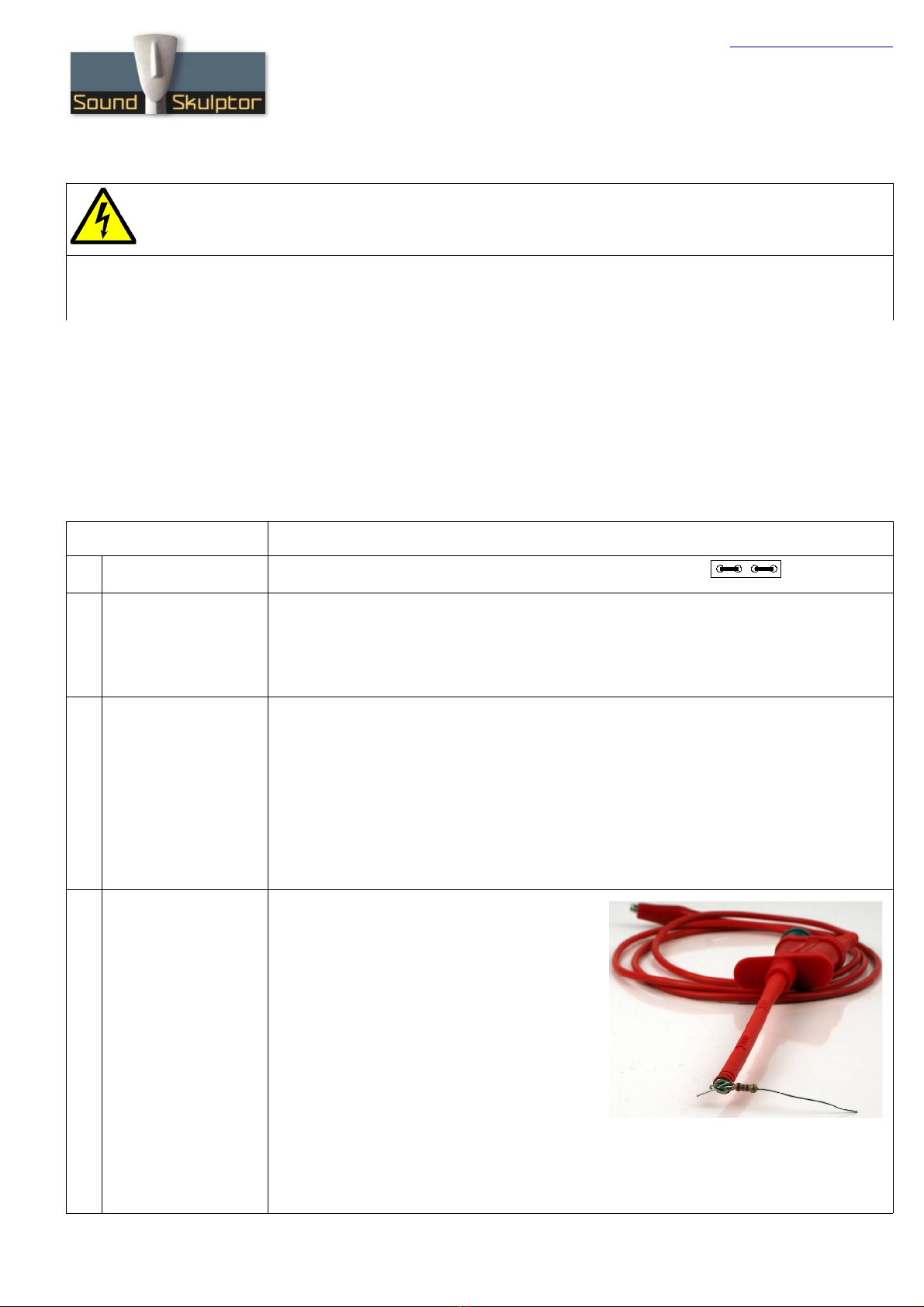
repare a discharge cable for the high voltage capacitors.
4Discharge cable
IM ORTANT
The circuit uses 300V DC voltages. Several
electrolytic capacitors are charged to this
potential. When power is removed, the tube
heaters turn off, leaving the tubes in a high
impedance state preventing the capacitors
discharge. This means that very high potentials
will remain on the circuit many minutes after the
power has been removed.
Before putting your fingers on the circuit, it is
necessary to discharge the capacitors.
Use a piece of insulated wire and a 1K to 10K
resistor connected to ground. The ground can
be taken on the ground bar that links the XLR plugs.
To discharge the caps, touch T 7 a few seconds with the resistor leg.
Copyright ©2008 SoundSkulptor

www.soundskulptor.com
Document revision 1.1 – Last modification : 27/06/11
Step Description
5. High voltage check Set your DMM to DC Volts on a 500 V scale and connect it between T 2 (GND) and T 7
(V+). Use test hooks and be careful not to create shortcuts.
lug in power and check that the 3 LEDs on the power supply unit are lighting normally. If
one or more LED is staying off or is lighting too low or too bright, immediately plug off
power and start checking your board.
Check that you get a positive voltage of 295 to 300 Volts on your DMM.
lug off power.
Discharge capacitors.
6Heater check Insert both tubes in their respective sockets. Do that progressively, without hardness,
the risk being to bend one of the tube pins.
Set your DMM to DC Volts on a 3V scale and connect it between T 6 and T 5. Use test
hooks and be careful not to create shortcuts.
lug in power.
The value displayed should ramp up from 0.2V to around 0.6V then back slowly to 0.56V
when the tubes get hot.
This value is the voltage across a 3.75 Ohms resistor, in serial connection with the heater
circuit. 0.56V means a current of 0.56 / 3.75 = 150mA in the filaments.
lug off power.
Discharge capacitors.
7. Sound check Connect the input and output XLR wires to the board terminals.
lug in a dynamic microphone to the input XLR.
Connect the output to your monitoring system. It can be a headphone amplifier or it can
go through one of your ADC inputs if you run a software studio.
Set gain switch to Mid, gain knob to minimum, Hi- ass switch up, Air switch centre, phase
switch up, 48V up and Output level to max.
lug in power and wait about 30 seconds for tubes warm up.
Turn up the gain knob until you hear the microphone. If the gain is not enough, switch to
High-Gain. Check that your micpre is working. Check the 3 switch gain positions, the High-
ass switch, the Air switch, the phase switch and the output level knob.
Make the same test with a static microphone, with the 48V switch set to On.
lug off power.
Set the 48V switch to Off.
Discharge capacitors.
8. DI check If you are using a SKM version 1, plug the board's flat cable to connector CN1 or CN2
on the DI02 board if it is not the case yet.
Insert an instrument jack into the corresponding front panel jack socket.
lug in power.
You should hear your instrument when playing.
lug off power.
Copyright ©2008 SoundSkulptor

www.soundskulptor.com
Document revision 1.1 – Last modification : 27/06/11
Step Description
9. Clip LED setup Warning : Do not forget to set your 48V phantom switch to OFF.
This setup will be based on voltage levels rather than on actual clipping because, in tube
preamps, the clipping comes in very progressively and it is difficult to hear.
Connect a 1KHz sine source to the input.
You can use your multitrack software loop playing a sine tone like the one that is
downloadable from the “Downloads & Useful links” section on our website. Route the
signal to an audio output and connect your DMM to this output. The DMM is set to AC
Voltage, on a 100 millivolts scale. Adjust the software output level in order to get
100mVAC. Connect this output your micpre input.
Set the gain potentiometer to 0 and the gain switch to High (top position).
lug in power and wait 30 seconds.
Warning : Use an insulated screw driver to adjust the trimmers.
Adjust 3 trimmer (Clip1) clockwise until it starts turning the LED red.
Now set the gain switch to Mid (centre position) and the output pad to maximum.
Increase the 1KHz level in software to 0.5V AC.
Set your DMM to a 20VAC scale and connect it on the output of the preamp, between
pins 2 and 3 of the output XLR.
Adjust the Gain potentiometer until you read 12.35V AC on the DMM. This is about
+24dBu.
Adjust 4 trimmer (Clip2) until it starts turning the LED red.
lug off power.
Discharge capacitors.
10. Congratulations You're done !
Copyright ©2008 SoundSkulptor
Table of contents
Other Sound Skulptor Amplifier manuals

Sound Skulptor
Sound Skulptor MP 599 User manual

Sound Skulptor
Sound Skulptor MP573 User manual

Sound Skulptor
Sound Skulptor MP 512 User manual

Sound Skulptor
Sound Skulptor MP73 User manual

Sound Skulptor
Sound Skulptor MP 566 User manual

Sound Skulptor
Sound Skulptor MP 599 User manual

Sound Skulptor
Sound Skulptor MP 512 User manual

Sound Skulptor
Sound Skulptor MP 512 User manual

Sound Skulptor
Sound Skulptor MP573 User manual

Sound Skulptor
Sound Skulptor MP73 User manual


