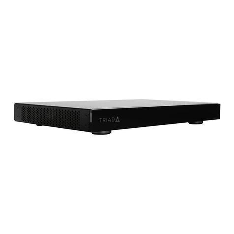
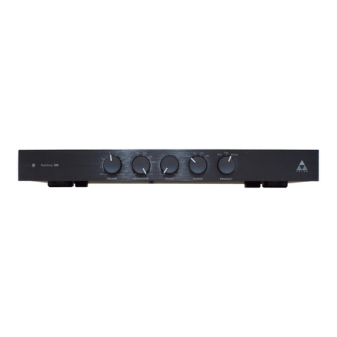
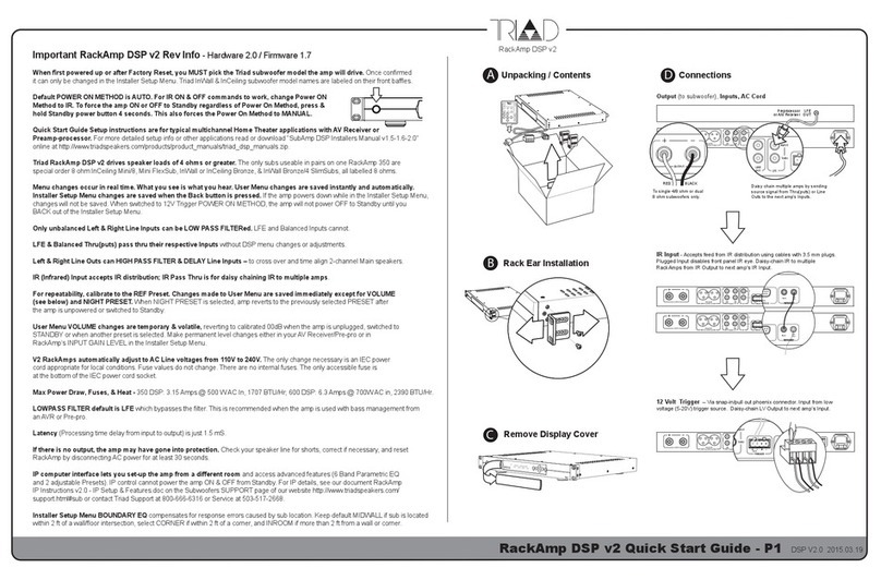
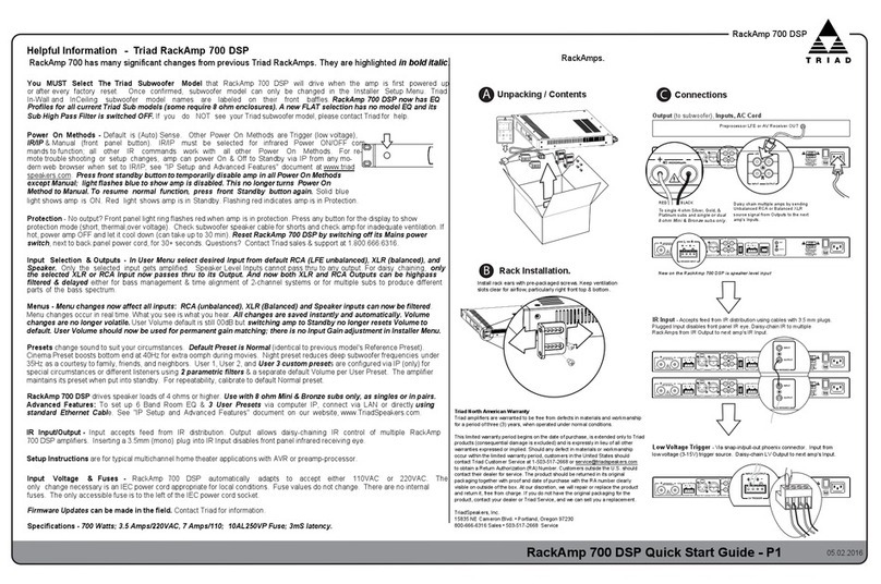
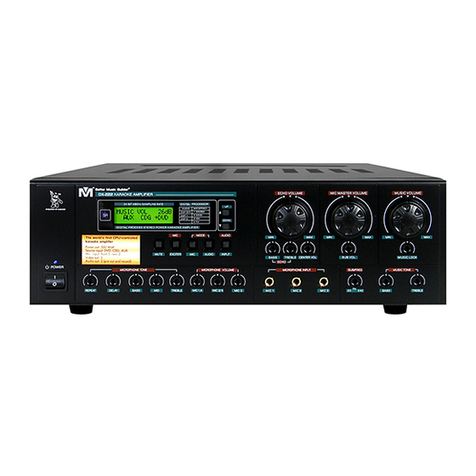
Triad rackamp 250 User manual

AMPLIFIER MANUAL
RackAmp 250
Engineered In The USA
Triad Speakers, Incorporated
•
Portland, Oregon
www.triadspeakers.com
WARRANTY INFORMATION
Triad Speakers Warranty Information
For your convenience, we have included space below for you to record your amplifi er
model and serial number, purchase date, dealer’s name, and phone number. You will need
the following information in the event your amplifi er needs servicing. Please keep this manual and
the sales receipt in a safe place.
Model: __________________________ Serial #: _______________________
Dealer Name: ____________________________________________________
Purchase Date: ___________________ Phone #: ________________________
Triad North American Warranty
Triad amplifi ers are warranted to be free from defects in materials and workmanship for a period
of three (3) years, when operated under normal conditions.
This limited warranty period begins on the date of purchase.
This limited warranty is extended
only to Triad products and is expressly in lieu of all other warranties expressed or implied.
Should any defect in materials or workmanship occur within the limited warranty period,
customers in the United States should contact Triad Customer Service at 1-877-264-6315,
to obtain a Return Authorization (RA) Number. Customers in Europe should contact their dealer
for service.
The product should be returned in its original packaging together with proof and date of
purchase with the RA number clearly visible on outside of the box. At our discretion, we will
repair or replace the product and return it, free from charge. If you do not have the original
packaging for the product, contact your dealer or Triad Service, and we will provide it for you.
Triad Speakers, Incorporated
15835 NE Cameron Blvd.
•
Portland, Oregon 97230
503.256.2600 Sales
•
877.264.6315 Toll Free Service
www.triadspeakers.com
Part #905-0250

The lightning fl ash with arrowhead
symbol, within an equilateral triangle,
is intended to alert you to the presence of
uninsulated “dangerous voltage” within the
product’s enclosure that may be of suffi cient
magnitude to constitute a risk of electric
shock to persons.
The exclamation point within an equilateral
triangle is intended to alert you to the
presence of important operating and mainte-
nance (servicing) instructions in the literature
accompanying the appliance.
IMPORTANT SAFETY INSTRUCTIONS
RISK OF ELECTRIC SHOCK
DO NOT OPEN
CAUTION
Explanation of Graphical Symbols
1.
Read Instructions
All the safety and operating
instructions should be read before the product is
operated.
2.
Retain Instructions
The safety and operating
instructions should be retained for future reference.
3.
Heed Warnings
All warnings on the product
and in the operating instructions should be
adhered to.
4
Follow Instructions
All operating and use
instructions should be followed.
5
Cleaning
Unplug this product from the wall
outlet before cleaning. Do not use liquid cleaners
or aerosol cleaners. Use a damp cloth for cleaning.
6.
Attachments
Do not use attachments not
recommended by the manufacturer, as they may
cause hazards.
7.
Water and Moisture
Do not use this product
near water—for example, near a bath tub, wash
bowl, kitchen sink, or laundry tub; in a wet basement;
or near a swimming pool; and the like. Follow the
manufacturer’s instructions, and use a mounting
accessory recommended by the manufacturer.
CAUTION: TO REDUCE THE RISK OF
ELECTRICAL SHOCK, DO NOT REMOVE
COVER (OR BACK). NO USER-SERVICEABLE
PARTS INSIDE. REFER SERVICING TO
QUALIFIED SERVICE PERSONNEL.
Important Information
8.
Accessories
Do not place this product on an
unstable cart, stand, tripod, bracket, or table. The
product may fall, causing serious injuries to a
child or adult, and serious damage to the product.
Use only with a cart, stand, tripod, bracket,
or table recommended by the manufacturer, or
sold with the product. Any mounting of the
product should follow the manufacturer’s
instructions, and should use a mounting
accessory recommended by the manufacturer.
9.
Movement
A product and cart combination
Movement A product and cart combination Movement
should be moved with care. Quick stops,
excessive force, and uneven surfaces may cause
the product and cart combination to overturn.
10.
Ventilation
Slots and openings in the cabinet are
provided for ventilation and to ensure reliable
operation of the product and to protect it from
overheating, and these openings must not be
blocked or covered. The openings should never
be blocked by placing the product on a bed, sofa,
rug, or other similar surfaces. The product should
not be placed in a built-in installation such as a
bookcase or rack unless proper ventilation is
provided or the manufacturer’s instructions
have been adhered to.
11.
Power Sources
This product should be operated
only from the type of power source indicated on
the marking label. If you are not sure of the type
of power supply to your home, consult your
product dealer or local power company.
For products intended to operate from battery
power, or other sources, refer to the operating
instructions.
12.
Grounding or Polarization
This product may be
equipped with a polarized alternating current line
plug (a plug having one blade wider than the
other). This plug will fi t into the power outlet only
one way. This is a safety feature. If you are unable
to insert the plug fully into the outlet, try reversing
the plug. If the plug should still fail to fi t, contact
your electrician to replace your obsolete outlet.
Do not defeat the safety purpose of the
polarized plug.
13.
Power-Cord Protection
Power-supply cords
should be routed so that they are not likely to
be walked on or pinched by items placed upon
or against them, paying particular attention to
cords at plugs, convenience receptacles, and the
point where they exit from the product.
14.
Lightning
For added protection for this product
during a lightning storm, or when it is left
unattended and unused for long periods of time,
RackAmp Specifications
2
11
18 5/16" ctr to ctr
18 3/8" Enclosure
Front View
Side View
Top View
Rear View
17 1/4" without Brackets
"
8
/
3
3
19" with Brackets
Removeable front panel
hides amplifier adjustments
3/4 View
Specifi cations
Dimensions:
Height: 3-1/2” (2U)
Width: 19” w/ears
Depth: 18-1/2”
Shipping Weight:
20 lbs.
Frequency Response:
20Hz to 250Hz, all models
Distortion:
THD+N @ 100HZ, Full Power = 0.2%
into 4 ohm load, all models
Dynamic Range:
118dBA, all models
Damping Factors:
(250W = 2,000)
(500W = 2,000) (1000W = 1,000)
Effi ciency @ full power into 4 ohm load:
RackAmp 250 84%
RackAmp 500 84%
RackAmp 1000 78%
Normal Operating Temperature:
All Models 37 deg. C
Output Power into 4 ohms:
RackAmp 250 209W rms continuous – 350W pk
RackAmp 500
500W rms continuous – 700W pk
RackAmp 1000
1000W rms continuous – 1,400W pk
AC Power (Run):
RackAmp 250 120VAC @ 3.15A – Stand-by 100 ma
RackAmp 250 120VAC @ 3.15A – Stand-by 100 ma
240VAC @ 2.50A – Stand-by 50 ma
RackAmp 500 120VAC @ 6.30A – Stand-by 108 ma
240VAC @ 3.15A – Stand-by 54 ma
RackAmp 1000
120VAC @ 10.0A – Stand-by 116 ma
120VAC @ 10.0A – Stand-by 116 ma
240VAC @ 6.30A – Stand-by 58 ma

RackAmp LINE-LEVEL Hookup Info
5
:
!
�
unplug it from the wall outlet and disconnect the
antenna or cable system. This will prevent
damage to the product due to lightning and
power-line surges.
14.
Overloading
Do not overload the wall outlets,
extension cords, or integral convenience
receptacles as this can result in a risk of fi re or
electric shock.
15.
Object and Liquid Entry
Never push objects
Object and Liquid Entry Never push objects Object and Liquid Entry
of any kind into this product through openings as
they may touch dangerous voltage points
or short-out parts that could result in a fi re or
electric shock. Never spill liquid of any kind on
the product.
16.
Servicing
Do not attempt to service this product
yourself as opening or removing covers may
expose you to dangerous voltage and other
hazards. Refer all servicing to qualifi ed personnel.
17.
Damage Requiring Service
Unplug this product
from the wall outlet and refer servicing to
qualifi ed service personnel under the following
conditions:
a) When the power-supply cord or plug is
damaged,
b) If liquid has been spilled, or objects have
fallen into the product,
c) If the product has been exposed to rain
or water,
d) If the product does not operate normally
by following the operating instructions. Adjust
only those controls that are covered by the
operating instructions, as an improper
adjustment of other controls may result in a
damage and will often require extensive work
by a qualifi ed technician to restore the
product to its normal operation,
e) If the product has been dropped or damaged
in any way, and
f) When the product exhibits a distinct change
in performance, this indicates a need for
service.
18.
Replacement Parts
When replacement parts
are required, be sure the service technician has
used replacement parts specifi ed by the
manufacturer or have the same characteristics
as the original part. Unauthorized substitutions
may result in fi re, electric shock, or other
hazards.
IMPORTANT SAFETY INSTRUCTIONS
19.
Safety Check
Upon completion of any service
Safety Check Upon completion of any serviceSafety Check
or repairs to this product, ask the service
technician to perform safety checks to determine
that the product is in proper operating
condition.
20.
Wall or Ceiling Mounting
The unit should be
Wall or Ceiling Mounting The unit should be Wall or Ceiling Mounting
mounted to a wall or ceiling only as
recommended by the manufacturer.
21.
Heat
The product should be situated away from
Heat The product should be situated away fromHeat
heat sources such as radiators, heat registers,
stoves, or other products (including amplifi ers) that
produce heat.
▲▲▲
10
3

Run / Stand-by Switch:
This push button switch is used to toggle the
amplifi er’s operating mode between Run and
Stand-by. In the Run mode the amplifi er is
operating normally. In the Stand-by mode the
amplifi er outputs are muted and the amp
is in idle drawing virtually no current from the AC
Mains and generating very little heat.
Run / Stand-by Indicator LED:
The BLUE LED on the front panel indicates
amplifi er status. When the LED is ON the amplifi er
is in the RUN mode. When the BLUE LED is OFF
and the Protect LED is YELLOW the amplifi er is in
the STAND-BY (MUTE) mode.
Power-on / Fault Indicator LED:
The GREEN LED on the front panel indicates
normal operation. RED indicates an over-temperature
or fault condition. In the event of a RED LED at the time
of installation, turn the amplifi er off, unplug the AC
Line Cord and check the output, cable, and speaker
for a short-circuit condition. If found, clear the short
circuit and continue the installation process. In the
event of a RED LED during normal operation, mute
the input signal to the amplifi er and wait a few
minutes for the GREEN LED to come on indicating the
amplifi er has cooled off and is ready to resume
normal operation.
Level Control:
This potentiometer adjusts the RackAmp’s gain
when using the amplifi er’s Line Input. Use this
control to match the amplifi er/speaker loudness to
the level of your front LCRs or Satellites. This control
has no effect when the Theater Input is in use.
Lowpass / Crossover Control:
This control is used to adjust the frequency response
of the amplifi er. The crossover pot controls a fourth
order (–24dB/oct) Linkwitz-Riley lowpass variable
fi lter. The span of control for the –6dB turnover
(or “knee”) frequency is 35Hz to 250Hz with a Q
of 0.707.
FRONT PANEL CONTROL INFO
Phase / Crossover Switch:
This is a four position switch used to change
output phase from 0 deg to 180 deg and
to enable or by-pass the Crossover function.
▲▲▲
P
osition 1:
0 deg Phase shift, Crossover enabled.
Position 2:
0 deg Phase shift, Crossover By-passed.
Use this setting when using a processor
with bass management.
Position 3:
180 deg Phase shift, Crossover enabled.
Position 4:
180 deg Phase shift, Crossover By-passed.
RackAmp LINE-LEVEL Hookup Info
4
:
!
:
!
:
!
�
4
9

RackAmp LINE-LEVEL Hookup Info
3
:
!
:
!
:
!
�
LOWPASS / CROSSOVER CONTROL
Low-frequency boost:
The entire RackAmp line is designed to provide
an alternative between maximized headroom and
extended bass response. The level control sets the
overall playback balance between the RackAmp
and associated satellite speakers.
Set the crossover to desired crossover
frequency, normally at the point where the satellite’s
response starts to drop. Then set the level
of the output from the RackAmp to match
the output of the satellite. This provides extra
low output, without the boominess associated with
just turning up the level.
The benefi t of this approach is that instead of
increasing overall output from the subwoofer, only
true bass is emphasized.
Underlapping:
In the case of a room response bump at or around
the crossover frequencies of the satellites, set the
controls as follows:
Set the level of the RackAmp so the extreme
low frequency portion of the response curve
(below 45Hz) is equal to that of the satellites.
Then set the lowpass crossover frequency
of the sub below the crossover frequency of
the satellites. This causes a dip in the summed
response, if set correctly, this can partially or
completely compensate for the room’s response.
Using the RackAmp’s Crossover Control
Overlapping:
In the case of a room response dip at or around the
crossover frequencies of the satellites, set the
controls as follows:
Set the level of the RackAmp so the extreme
low frequency portion of the response (below
45Hz) is equal to that of the satellites. Then set
the lowpass crossover frequency control on the
sub above the crossover frequency of
the satellites. This causes a bump in the summed
response, if set correctly, this can partially or
completely compensate for the room response.
▲▲▲
8
5

RackAmp REAR PANEL Info
:
!
Left and Right Line-Level Inputs:
These inputs accept full-range, line-level signals from
an external source. The full-range Left and Right input
signals are mixed together by the amplifi er’s input
circuitry and applied to a lowpass fi lter. The lowpass fi lter
removes unwanted mid- & high-frequency components
from the signal and delivers low-frequency audio to the
power amplifi er.
Sub Line-Level Input:
The primary purpose of this input is to simplify wiring
to the sub and aid in daisy chaining multiple subs. This
input accepts a full-range, line-level signal from an
external source. The signal is buffered and passed
directly to the Sub Output without any processing then
goes to the local input circuitry for conditioning by
the low-frequency fi lter circuits in the same manor as
the Left and Right Inputs.
Sub Line-Level Output:
The primary purpose of this output is to aid in
daisy chaining multiple subs. This signal is a
buffered output of the Left, Right or Sub inputs.
The full-range signals from the line-level inputs are
presented at this output, no signal conditioning,
or fi ltering is done to this signal. The level
control does not effect the gain of this output.
AC Input:
This amplifi er is designed to operate from a
115–230VAC 50-60Hz power source capable of
delivering up to 10A of current.
Refer to the markings on the amplifi er to
determine the proper operating voltage for the model
you are working with.
AC Power Switch:
This is a 16A/125vac, 10A/250vac double pole
single throw power switch that complete disconnects
the AC Mains from the amplifi er circuitry.
▲▲▲
RackAmp LINE-LEVEL Hookup Info
:
!
�
:
!
�
1
2
6
7
THE OUTPUT OF THIS AMPLIFIER
CAN GENERATE POTENTIALLY LETHAL
VOLTAGES.
THERE ARE NO USER SERVICEABLE
COMPONENTS IN THIS AMPLIFIER.
LETHAL VOLTAGES PRESENT INSIDE THIS
EQUIPMENT DO NOT OPEN OR DISASSEMBLE
THIS UNIT FOR ANY REASON. IN THE EVENT
OF FAILURE, TURN OFF THE AMPLIFIER AND
CONTACT TRIAD SPEAKERS INC FOR SERVICE.
Specialized Setup Information
Maximum Bass Extension:
For fully extended bass response to 20Hz, use Left
and/or Right or the Sub Input.
Maximum SPL Output:
Drive both the Left and Right Inputs from separate
sources.
Amplifi er Output:
This is the amplifi er’s high current output, used to
drive a speaker with 4-ohm or greater impedance.
Line Level Inputs:
The sub Input and the Left & Right Inputs are the
same; all three signals are processed by the
amplifi er’s level control, crossover, and phase
controls of the amplifi er.
Sub Output:
The Sub Output is a buffered output of the summed
Left & Right and Sub Inputs. Level, Crossover, and
Phase control have no effect on Sub output level.
The buffered Sub Out allows you to daisy chain
as many amplifi ers as you want without loss of
signal level.
Table of contents
Other Triad Amplifier manuals
