TriCom TCR-SPK-DUALv2 User manual

OPERATOR'S MANUAL
TCR-SPK-DUALv2
AMPLIFIED DUAL-NET SPEAKER
DOCUMENT # 90400-01480
Tricom Research, Inc.
•
www.tricomresearch.com
17791 Sky Park Circle, Suite J, Irvine, CA 92614
Phone: (949) 250-6024 Fax: (949) 250-6023

i
TCR-SPK-DUALv2 OPERATOR'S MANUAL
Revision History - Document 90400-01480
REVISION
DESCRIPTION
DATE
A
INITIAL RELEASE
12 SEPTEMBER 2020
Note: The latest version of this manual can be downloaded from our website at
www.tricomresearch.com.

ii
TCR-SPK-DUALv2 OPERATOR'S MANUAL
TABLE OF CONTENTS
1.0 INTRODUCTION
1.1 General Information ................................................................................................. 1
1.2 Abbreviations And Glossary .................................................................................... 2
1.3 Speaker ..................................................................................................................... 3
1.4 Cables ....................................................................................................................... 3
1.5 Specifications ........................................................................................................... 3
2.0 OPERATION
2.1 General Information ................................................................................................. 5
2.2 Controls .................................................................................................................... 5
2.3 Power On, Initialization, And Set Up ....................................................................... 5
2.4 Pushbutton Functions ............................................................................................... 5
2.5 USB Charging Port ................................................................................................... 7
2.6 Auxiliary Audio Port ................................................................................................ 7
2.7 Handset Operation .................................................................................................... 7
3.0 INSTALLATION
3.1 Preparation For Use .................................................................................................. 7
3.2 Mounting Provisions ................................................................................................ 7
3.3 DC Input Power ........................................................................................................ 9
3.4 Radio Interfaces ...................................................................................................... 10
3.5 Handset Interfaces .................................................................................................. 10
3.6 Firmware Updates .................................................................................................. 10
3.7 Optional Slave Speaker .......................................................................................... 10
LIST OF TABLES
Table 1-1. General Specifications ................................................................................................ 3
Table 1-2. Interconnect Characteristics ........................................................................................ 4
Table 2-1. Front Panel Controls ................................................................................................... 5
Table 3-1. DC Input Power Connector Pinout ............................................................................. 9
LIST OF FIGURES
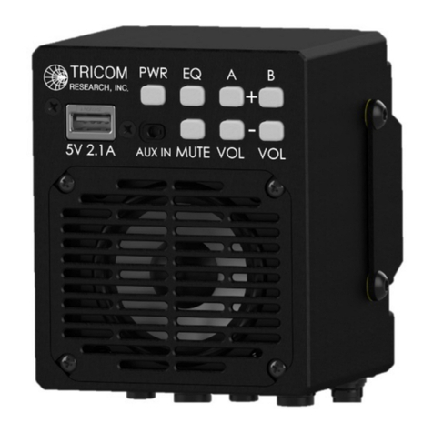
Figure 1-1. TCR-SPK-DUALv2 Amplified Dual-Net Speaker ................................................... 1
Figure 3-1. TCR-SPK-DUALv2 Outline Drawing (w/ Mount) ................................................... 8
Figure 3-2. TCR-SPK-DUALv2 Outline Drawing (w/o Mount) ................................................. 8
Figure 3-3. DC Input Power Connector (Tajimi R05-RB5M) ..................................................... 9
Figure 3-4. DC Power Cable 120" (Part Number 77500-00923) ................................................. 9

1
1.0 INTRODUCTION
1.1 GENERAL INFORMATION
The TCR-SPK-DUALv2 is the next generation of Tricom's Amplified Dual-Net Tactical Speaker. As
one of the smallest and most capable amplified speakers on the market, the TCR-SPK-DUALv2 easily
integrates into vehicular, maritime, airborne, and fixed station applications. The speaker amplifies two
tactical radio nets with intuitive operation, enables simultaneous transmit across both nets, and
supports up to two handsets per net. Utilizing optional cable configurations, the TCR-SPK-DUALv2
can be tailored to nearly any integration.
• Integrated high-power audio amplifier
• Dual Digital Signal Processors (DSP) for superior audio performance
• Selectable EQ settings ensure quality sound in various environments
• Simplified front panel, compact and low-profile
• Individual net volume controls with rapid mute function
• Mute and "missed traffic" LED indicators for each net
• Dimmable, NVG compatible LEDs
• Compatible with existing communications equipment
• Local handset function regardless of speaker power
• Individual handset for each net, no single point of failure
• Supports up to two handsets for each net
• Field replaceable driver
• Optional cable configurations available, tailored to system integration
• USB charging port
• Auxiliary audio in, automatically mutes on any audio traffic (incoming or outgoing)
Figure 1-1. TCR-SPK-DUALv2 Amplified Dual-Net Speaker

2
1.2 ABBREVIATIONS AND GLOSSARY
AGC Automatic Gain Control
CONN Connector
dB Decibel
GND Ground
HDST Handset
Hz Hertz
I/O Input/Output
kHz Kilohertz
LED Light Emitting Diode
PTT Push to Talk
RX Receive
VDC Volts, Direct Current
W Watt
TX Transmit

3
1.3 SPEAKER
The TCR-SPK-DUALv2 Amplified Dual-Net Speaker has a sealed, rugged enclosure finished in
black anodize and designed to withstand the elements and resist corrosion. The enclosure houses
all electronic subassemblies.
1.4 CABLES
Five multi-conductor cables connect the speaker to the DC power, communications system(s), and
handsets. Multiple installation scenarios are supported using optional cable configurations.
Interconnect characteristics are shown in Table 1-2.
1.5 SPECIFICATIONS
Note: Information in Table 1-1 is included for reference only and does not constitute a
warranty of performance.
Table 1-1. General Specifications
DC Input 12-32 VDC
Audio Input Standard Tactical Radio Audio
Audio Frequency Response Radio: 300-3,000 Hz
Aux: 125-20,000 Hz
Distortion < 2% at Full Power
Speaker TX Mute Automatic with PTT
Volume Controls Net A+, Net A-
Net B+, Net B-
*each with audio confirmation
Mute (Cycles Mute A/B, A, B, OFF)
Indicators Power
Mute
Missed Traffic
USB Charging Port 5V 2.1A Charging Only
Auxiliary Audio In 3.5mm
Environmental Designed to meet MIL-STD-810, IP67
Electrical Designed to meet MIL-STD-1275
Dimensions 4.13” H x 3.87” W x 3.26” D (including mount)
Weight 2.2 lb

4
Table 1-2. Interconnect Characteristics
CONN
SIGNAL/PIN
DETAIL
POWER
Power/Auxiliary
Tajimi R05-RB5M
Pin A
VDC+
Pin B
Electrical Ground (GND)
Pin C
Optional Slave Speaker +
Pin D
Optional Slave Speaker -
Pin E
Spare
HDST A
(MAIN A/B)
Handset(s)
Tajimi R05-RB8F
Pin A
GND
Pin B
RX Audio A (Audio from Radio A)
Pin C
PTT A
Pin D
TX Audio A (Handset Mic to Radio A)
Pin E
GND
Pin F
RX Audio B (Audio from Radio B)
Pin G
PTT B
Pin H
TX Audio B (Handset Mic to Radio B)
Shell
Shield
RADIO A
Radio A
Tajimi R05-RB5F
Pin A
GND
Pin B
RX Audio A
Pin C
PTT A
Pin D
TX Audio A
Pin E
Spare
Shell
Shield
HDST B
(AUX A/B)
Handset(s)
Tajimi R05-RB8F
Pin A
GND
Pin B
RX Audio A (Audio from Radio A)
Pin C
PTT A
Pin D
TX Audio A (Handset Mic to Radio A)
Pin E
GND
Pin F
RX Audio B (Audio from Radio B)
Pin G
PTT B
Pin H
TX Audio B (Handset Mic to Radio B)
Shell
Shield
RADIO B
Radio B
Tajimi R05-RB5F
Pin A
GND
Pin B
RX Audio B
Pin C
PTT B
Pin D
TX Audio B
Pin E
Spare
Shell
Shield

5
2.0 OPERATION
2.1 GENERAL INFORMATION
The TCR-SPK-DUALv2 can be used for operation once it has been installed, as described in
Section 3.
2.2 CONTROLS
The TCR-SPK-DUALv2 has an intuitive front panel with seven buttons, as shown in Table 2-1:
Table 2-1. Front Panel Controls
CONTROLS
TYPE
FUNCTION
PWR
Pushbutton Switch
Power On, Power Off
EQ
Pushbutton Switch
Cycles Equalizer Settings
MUTE
Pushbutton Switch
Cycles Mute Conditions
A+
Pushbutton Switch
Increases Net A Volume
A-
Pushbutton Switch
Decreases Net A Volume
B+
Pushbutton Switch
Increases Net B Volume
B-
Pushbutton Switch
Decreases Net B Volume
2.3 POWER ON, INITIALIZATION, AND SET UP
Pressing the front panel PWR pushbutton initiates a Power On Self-Test (POST) process, after
which the speaker is ready for operation.
Net A and Net B volume is adjusted using the A+/A- and B+/B- pushbuttons. The radio
volume control controls handset volume. Set Up is complete once the unit is powered on and
proper volume levels set.
NOTE: A minimum radio volume level, equivalent to that which can be heard on the standard
handset, is required for proper operation of the speaker's auto noise gating and AGC functions.
Ensure receiving radio is set to the proper minimum volume.
Power down (off/bypass) is accomplished by pressing and holding the PWR pushbutton for
greater than two seconds.
NOTE: Upon application of DC Power, the TCR-SPK-DUALv2 returns to its previous
operating state, including all settings.
2.4 PUSHBUTTON FUNCTIONS
PWR Pushbutton – Power On/Off - To turn the speaker on, press the PWR button
momentarily. The speaker will turn on, complete a post process, and is then ready for
operation in the same state as it was last powered off. The PWR button is backlit green when

6
the speaker is on. Press and hold the PWR button for more than two seconds to power down
the speaker. While off, handset and radio connections are straight pass-throughs enabling
communication using the handsets.
PWR Pushbutton – Brightness - To change the brightness of button backlighting, press the
PWR button momentarily. Each press will cycle through four levels of brightness: bright,
medium, medium-low, low.
EQ Pushbutton – Equalizer – Pressing the EQ button cycles equalizer settings for radio and
auxiliary audio, each with four factory settings: flat, low, mid, and high emphasis. Each
momentary press of the button results in a single tone that corresponds to the setting; a dual
tone indicates the factory setting. Settings for radio traffic are selected by pressing the EQ
button while receiving radio traffic or when no audio is playing. Settings for auxiliary audio
are selected by pressing the EQ button while playing auxiliary audio.
MUTE Pushbutton – Mute – Pressing the Mute button cycles mute conditions: Mute A/B,
Mute A, Mute B, Mute OFF. A single short tone indicates Mute OFF has been selected. The
Mute button is backlit green during any active mute condition.
NOTE: The mute button only mutes radio audio. Any audio played through the Aux port will
not be muted.
A+ Pushbutton – Volume – Momentary presses of the A+ button increases volume in ten
steps (audio logarithmic taper) with each increase indicated by a single short tone. A single
long tone indicates maximum volume has been selected. Holding the A+ button increases
volume through the steps continuously. The A+ button is backlit green anytime Net A is
muted. The A+ button will flash when Net A is muted and radio traffic is detected, alerting
the user to missed radio traffic.
A- Pushbutton – Volume – Momentary presses of the A- button decreases volume in ten
steps with each increase indicated by a single short tone. A single long tone indicates
minimum volume has been selected. Holding the A- button decreases volume through the
steps continuously.
B+ Pushbutton – Volume – Momentary presses of the B+ button increases volume in ten
steps (audio logarithmic taper) with each increase indicated by a single short tone. A single
long tone indicates maximum volume has been selected. Holding the B+ button increases
volume through the steps continuously. The B+ button is backlit green anytime Net B is
muted. The B+ button will flash when Net B is muted and radio traffic is detected, alerting the
user to missed radio traffic.
B- Pushbutton – Volume – Momentary presses of the B- button decreases volume in ten steps
with each increase indicated by a single short tone. A single long tone indicates minimum
volume has been selected. Holding the B- button decreases volume through the steps
continuously.
NOTE: The speaker volume buttons do not change auxiliary audio volume.

7
2.5 USB CHARGING PORT
The USB charging port is provided for charging USB devices only; no data connection exists.
The port provides 5 VDC and up to 2.1A for charging.
2.6 AUXILIARY AUDIO PORT
The TCR-SPK-DUALv2 has a standard 3.5mm auxiliary audio-in port for audio playback.
Audio playback is automatically muted with incoming radio traffic or handset PTT. Auxiliary
audio volume is set by the auxiliary source. The audio playback function has a five second
delay after audio is started and after an automatic mute from incoming radio traffic or handset
PTT. After the five second delay, audio playback ramps back up to the auxiliary source
volume over a five second period.
2.7 HANDSET OPERATION
The handsets connected to the speaker control their respective radios. If single handset cables
(HDST A and HDST B) are used: the handset connected to HDST A will only control Radio
A, and; the handset connected to HDST B will only control Radio B. If dual handset cables
are used (MAIN A/B and AUX A/B): the MAIN A and AUX A handsets control Radio A,
and; the MAIN B and AUX B handsets control Radio B.
3.0 INSTALLATION
3.1 PREPARATION FOR USE
After unpacking the system and inspecting for physical damage, select an appropriate location
for the speaker. Although the TCR-SPK-DUALv2 is weather-resistant, placing it in a location
where it is protected from rain, sunlight, and salt spray will increase its service life.
3.2 MOUNTING PROVISIONS
The TCR-SPK-DUALv2 can be mounted using the supplied mounting bracket with six #8
through holes, see Figure 3-1. Alternatively, the speaker can be flush mounted using four 8-32
x .25" deep tapped screw holes on the rear panel, see Figure 3-2. Ensure proper access to
connectors and clearance for cables.

8
Figure 3-1. TCR-SPK-DUALv2 Outline Drawing (w/ Mount)
Figure 3-2. TCR-SPK-DUALv2 Outline Drawing (w/o Mount)

9
3.3 DC INPUT POWER
The DC input power connector, shown in Figure 3-3, is compatible with a specific power
cable fitted with a matching Tajimi female connector. A typical power cable is shown in
Figure 3-4. Note that the speaker has true reverse polarity protection, including protection
from connecting the positive voltage input to Pin B (GND) with a grounded chassis.
Figure 3-3. DC Input Power Connector (Tajimi R05-RB5M)
Table 3-1. DC Input Power Connector Pinout
Pin
I/O
Description
A
I
12-32 VDC
B
I
Electrical Ground (GND)
C
O
Optional Slave Speaker +
D
O
Optional Slave Speaker -
E
I/O
Spare
Figure 3-4. DC Power Cable 120" (Part Number 77500-00923)
(R05-PB5F)

10
3.4 RADIO INTERFACES
The speaker can connect to two radios, labeled RADIO A and RADIO B.
3.5 HANDSET INTERFACES
The speaker has two handset cable connectors labeled HDST A (MAIN A/B) and HDST B
(AUX A/B). If the integration requires only 2 handsets, 1 for Radio A and 1 for Radio B, then
the HDST A and HDST B cables will be used. If the user requires 4 handsets, 2 for Radio A
and 2 for Radio B, then the MAIN A/B and AUX A/B cables will be used.
3.6 FIRMWARE UPDATES
The TCR-SPK-DUALv2 firmware may be updated through the front USB connector when put
into bootloader mode. Contact for details.
3.7 OPTIONAL SLAVE SPEAKER
The TCR-SPK-DUALv2 has the capability of connecting an additional slave speaker via its
power cable. The same amplified mono audio signal is sent to the slave speaker. Contact for
details.
Table of contents
Other TriCom Speakers manuals

